1
Barton® Model 200A/200AS
Differential Pressure Indicator
User Manual
Manual No. 9A-10055, Rev. 01
January 2008
Table of Contents
SAFETY .................................................................................................2
SECTION 1 - INTRODUCTION
1-1. General ............................................................................................3
1-2. Main Components ..........................................................................3
1-3. Indicator Specifications...................................................................3
SECTION 2 - INSTALLATION
2-1. General ............................................................................................4
2-2. Mounting/Piping/DPU Installation . .............................................4
2-3. Startup..............................................................................................4
SECTION 3 - MAINTENANCE AND CALIBRATION
3-1. Required Tools (Toolkit p/n 9A-0288-1032B)...............................5
3-2. DPU Installation/Test/Calibration/Maintenance . .......................5
3-3. Bezel/Lens (or Cover) Installation and Removal ........................5
3-4. Calibration Check ...........................................................................5
3-5. Pointer Installation and Removal .................................................6
3-6. Complete Calibration .....................................................................6
3-7. Overrange Stop Adjustment...........................................................7
3-8. DPU Maintenance...........................................................................8
3-9. Locking Drive Arm to Torque Tube...............................................8
3-10. Troubleshooting.............................................................................9
SECTION 4 - PARTS DRAWINGS/PARTS LISTS
Table 4-1. 200A Parts List.....................................................................11
Table 4-2. 200AS Parts List...................................................................13
SECTION 5 - INSTALL/DIMENSIONAL DRAWINGS
Product Warranty..................................................................................16
(This manual is for the Differential Pressure Indicator only. Before installing or operating
this instrument, refer to Model 199 DPU manual, P/N 9A-10030.)
SAFETY
Before installing this instrument, become familiar with the installation instructions in Section 2 and in the Model 199 DPU manual.
DANGER notes indicate the presence of a hazard which will cause severe personal injury, death, or substantial property damage if warning is ignored.
WARNING notes indicate the presence of a hazard which can cause severe
personal injury, death, or substantial property damage if warning is ignore.
CAUTION notes indicate the presence of a hazard which will or can cause moderate personal injury or property damage if warning is ignored.
DANGER, WARNING, and/or CAUTION notes that appear on the following
pages of this manual should be reviewed before proceeding: None. (Important!
Before installing or operating this instrument, review all safety notices contained
in the Model 199 DPU manual.)
SECTION 1 - INTRODUCTION
1-1. General
The Barton Models 200A (standard case) and 200AS (optional 316 stainless steel
case) indicators measure differential pressure, fluid flow rate, or liquid level. For
fluid flow measurements, the indicator is connected by piping to the low- and
high-pressure sides of a primary device (e.g., orifice plates, venturis, or flow
tubes) located in the process run. For liquid level applications, variations in the
level of the liquid within the process vessel produce changes in differential pressure used to indicate the liquid height.
The indicating pointer travels through a 270 degree arc over a six-inch diameter
scale. The movement has a micrometer screw for range adjustment. Pointer hub
adjustment can be made without removing the scale plate or pointer. Range and
linearity adjustments are accessible after removal of the scale plate.
Model 200 AS is recommended for use in corrosive environments.
1-2. Main Components
The 200A consists of two major components: an actuating unit (differential pressure unit) and the case enclosed indicating instrument.
A. Actuating Unit (DPU) - Model 199 DPU. For detailed information on the
actuating differential pressure unit, see the Model 199 DPU manual (P/N 9A10030).
B. Case (Indicator)
1-3. Indicator Specifications
Accuracy:
0-10” w.c. to 0-349” w.c.
(255 mm to 890 m).............±1/2% of full-scale differential pressure
0-350” w.c. to 0-100 psi
(890 m to 6.7 bar)..............±3/4% of full-scale differential pressure
Temperature Limits...............-40°F/°C to +180°F (+80°C);
+35°F to +180°F (+1°C to +80°C) for water-filled units
Dimensions............................per model number and housing rating. See outline
dimensional drawings in section 5.
1-4. Theory of Operation
The bellows within the DPU moves in response to changes in the differential
pressure monitored at the high and low pressure sides of the primary device
installed in the process run. The DPU bellows movement is mechanically transferred to the indicator mechanism through a rotating torque tube shaft. As the
torque tube rotates, the drive arm transmits the motion through the connecting
link to the indicating pointer. The pointer travels through a 270 degree arc to
indicate measurement on the 6-in. scale plate.
The 6-in. scale can be printed as required, in uniform increments for differential
pressure, static pressure, or liquid height or in square-root increments for direct
flow measurements. Special scales can be furnished to indicate the amount of
liquid in a tank.
SECTION 2 - INSTALLATION
2-1. General
The instrument should be inspected at time of unpacking to detect any damage
that may have occurred during shipment.
Note: The unit was checked for accuracy at the factory — do not change any of
the settings during examination or accuracy will be affected.
For applications requiring special cleaning/precautions, a polyethylene bag is
used to protect the instrument from contamination. This bag should be removed
only under conditions of extreme cleanliness.
2-2. Mounting/Piping/DPU Installation
Refer to the Barton Model 199 DPU user manual (Part No. 9A-10030).
NOTICE: Do not turn instrument by grasping the instrument case - this can
result in damage to the case. Always thread pipe into instrument.
2-3. Startup
For startup procedures, warning notices, and information, refer to the separate
DPU Manual that is appropriate for the instrument model being installed.
SECTION 3 - MAINTENANCE AND CALIBRATION
3-1. Required Tools (Toolkit p/n 9A-0288-1032B)
Tool
Purpose
Pointer puller Pointer removal
Small screwdriver Calibration adjustments
Medium screwdriver Bezel removal/DPU bracket screws
1/8” Open-end wrench Calibration adjustments
1/8 Hex Allen wrench Switch setpoint adjustment
3-2. DPU Installation/Test/Calibration/Maintenance
Refer to the Barton Model 199 DPU user manual (Part No. 9A-10030).
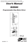
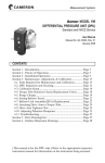
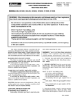
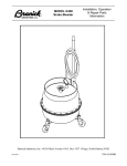
3-3. Bezel/Lens (or Cover) Installation and Removal
Whenever the bezel/lens is installed, the bezel gasket (p/n 9A-0277-0026C) must
be installed as shown below:
Figure 3-1.
Bezel/Lens
To remove the bezel and cover lens
on non-explosionproof units:
1. Loosen three screws on the front
of bezel.
2. Tilt out bottom of bezel and
slide bezel upward.
The two snubbers (p/n 9A-0266-0028C) on the scaleplate should not be compressed against the lens cover and the pointer should not touch the lens.
Notice
Ensure correct bezel gasket orientation before placing instrument back in service.
Incorrect bezel gasket orientation will cause the instrument indicator to jam,
resulting in inaccurate readings.
3-4. Calibration Check
Normally all that is required to put switch into service is to verify that it remains
at factory-set calibration, per the following:
1. Securely mount unit in an appropriately level position and connect DPU to a
standard pressure source, per Model 199 DPU manual.
2. If zero indication is incorrect, remove bezel/lens (cover on explosionproof
units) and reset pointer to zero. Note: For an exact zero setting, hold the
hexagon hub with a wrench and carefully slip the pointer on its hub until it
points to zero graduation. Replace bezel/lens (or cover).
3. To test for reverse travel, connect pressure source to LP housing and vent
HP housing. Apply pressures approximately 150% of the differential pressure range. The pointer should move approximately 5% to 10% below zero.
4.
5.
6.
7.
To test for overtravel, connect pressure source to HP housing and vent LP
housing. Apply pressures approximately 150% of the differential pressure
range. Pointer should move approximately 5% to 10% above fullscale.
Apply 0%, 50% and 100% of full-scale pressure. If indication is within
specified limits, instrument calibration is satisfactory and no adjustments are
necessary. If indications are incorrect, perform calibration procedure (see
section 3-6).
Make sure instrument zero indication is correct; otherwise, repeat Step 2.
Verify switch setpoints (see section 3-7, page 7).
3-5. Pointer Installation and Removal
A. Pointer Installation
Figure 3-2.
1. Position pointer on movePointer Puller
ment shaft with pointer set
at zero scale. If necessary,
enlarge hub hole using a
tapered broach (in toolkit)
(p/n 9A-0288-1032B).
2. Lightly tap pointer hub with
a hand-set or other flat-end
tool. Use perpendicular
blows to avoid bending
shaft.
3. Check calibration over entire range (see section 3-8.). If unit is correctly
calibrated, secure pointer to movement shaft by tapping hub with a
hand-set or other flat-end tool.
B. Pointer Removal
Pointer is removed with Barton Pointer Puller (p/n 9A-0163-0005B), which is
included in the toolkit (p/n 9A-0288-1032B).
1. Slide pointer puller along pointer until pin protruding from tip of screw
in pointer puller is directly over movement shaft and arms of pointer
puller are directly under pointer.
2. Gently turn knurled head of screw clockwise, pushing pin against movement shaft and lifting pointer with arms. Finger pressure should be
sufficient to pull the pointer free. If more pressure is required, insert an
Allen wrench into head of the screw for leverage. Avoid applying excessive pressure, which can cause the pin to break.
3-6. Complete Calibration
A complete calibration of the instrument is required whenever the DPU assembly
is replaced. Refer to the Model 199 DPU manual before performing this calibration procedure.
1. Securely mount instrument in an approximately level position and connect
DPU into the test setup, as described in the Model 199 DPU manual.
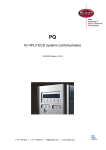
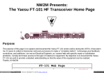
2. Align linkage between drive arm and movement. (Figure 3-3 shows proper
alignment at 50% differential pressure.) Inspect parts for straightness and
pivot-fit without binding.
3.
Set pointer at zero on scale by slipping pointer on hub. Hold tip of pointer
and turn hub with wrench.
4. Apply 100% differential pressure. If pointer exceeds 100% on scale,
lengthen range arm. Remove pressure.
5. Set zero and span, using hub for zero adjustment and range adjust screw on
the movement for span adjustments.
6. Apply 50% differential pressure. If pointer does not indicate 50% scale, a
linearity adjustment is necessary. Loosen drive arm screw and move arm to
shift pointer in direction of error (approx. 10:1). Tighten drive arm screw.
7. Release pressure and reset pointer at zero. Check the span. If gear in movement reaches limit of travel as a result of linearity adjustment (step 6), slip
range arm along gear approximately 5 degrees from normal 37.5 degree
angle to approximately 43 degrees.
Range arm is slipped by applying pressure to range arm with thumb, while
holding gear firmly in place. Retest
pointer response at 50% and 100%
differential pressure, and adjust linkage
until readings are acceptable.
8. Apply 0%, 25%, 50%, 75%, 100%,
75%, 50%, 25%, and 0% of differential
pressure consecutively to instrument
without overshoot. Lightly tap
indicator to overcome friction.
Figure 3-3.
Pointer should
Linkage Alignment
accurately indi(50% DP)
cate each applied
pressure.
9. Test instrument repeatability by applying 0%,
50%, 0%, 50% differential pressure. Indicator should accurately indicate
each applied pressure.
10. Set overrange stops to prevent pointer from striking snubbers on scale. See
section 3-7 (Overrange Stop Adjustment). Tighten all screws. Test setting
by manually moving pointer from zero position to 50%, then let the pointer
return freely. An off-set in zero reading indicates pointer slippage. If necessary, tap pointer hub to tighten it to shaft.
3-7. Overrange Stop Adjustment
1. Apply sufficient pressure to the high pressure housing to deflect the pointer
against the snubber on the scale plate. Slide the upper overrange stop against
the drive arm and tighten the overrange stop screw.
2. Apply sufficient pressure to the low pressure housing to deflect the pointer
against the zero stop snubber on the scale plate. Slide the zero-stop against
the drive arm and tighten the zero-stop screw.
3. Remove the pointer and calibration scale. Replace the pointer at zero
(adjust zero as necessary). Replace the lens and bezel assembly.
3-8. DPU Maintenance
A. DPU inspection/cleaning/repair/service procedures, along with applicable
WARNING notices, are presented in the Model 199 DPU manual.
3-9. Locking Drive Arm to Torque Tube
Refer to Model 199 DPU manual.
Figure 3-4. Locking Drive Arm to Torque Tube
1.
2.
Slip drive arm over torque tube shaft; clear end of torque-tube housing by
approximately 0.030-inches before securing to prevent interference.
To tighten drive arm assembly onto torque-tube shaft:
a. While supporting block/shaft, tighten clamp screw until snug to shaf.
b. Still supporting block/shaft, tighten clamp screw an additional:
• Sintered: 1/3 to 1/2 turn (This screw can normally turn one full revolu
tion before breaking.)
• Slotted: 1/4 to 1/3 turn (The slot in the slotted clamp block should
still be open.)
3-10. Troubleshooting
Refer to Table 3-1 for troubleshooting information. Also, see the Model 199 DPU
manual.
Table 3-1. Troubleshooting
Problem
Low or No
Indication
Possible
Source
DPU
Indicator
Probable
Cause
Corrective Action
—
See Model 199 DPU manual.
Loose movement
Out of calibration
High
Indication
Piping or
primary
source
DPU
Indicator
Erratic
Indication
Tighten/replace movement.
Calibrate unit.
Dirty or corroded
mechanism
Clean/replace mechanism.
Pointer loose
Tighten pointer.
—
See Model 199 DPU manual.
—
See Model 199 DPU manual.
Loose arms
Tighten mechanism.
Out of Calibration
Calibrate unit.
Primary
Element
—
See Model 199 DPU manual.
Piping
—
See Model 199 DPU manual.
DPU
—
See Model 199 DPU manual.
Indicator
Movement
dragging or dirty
Adjust/clean movement.
Pointer dragging
on scale plate
Adjust pointer position.
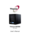
SECTION 4 - PARTS DRAWINGs/PARTS LISTs
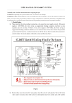
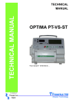
Figure 4-1. 200A Parts Drawing
10
Table 4-1. 200A Parts List
Item
Per
Unit
Description
Part No.
1
DIFFERENTIAL PRESSURE UNIT, MODEL 199
1
2*
SCREW, BEZEL, SLOTTED
SEE DPU
MANUAL
9A-0181-0007C
3
BEZEL (PART OF ITEM #24)
9A-0277-0029C
1
4*
LENS, COVER (PART OF ITEM #24)
9A-0181-0038C
1
5*
GASKET, BEZEL (PART OF ITEM #24)
9A-0277-0026C
1
6*
POINTER ASSEMBLY:
3
1
WHITE
9A-0288-0030B
7*
BLACK
SCREW, SCALE PLATE, 4-40 x 3/16, SST
9A-0288-0031B
9A-0114-0023J
8**
SCALE PLATE
4
1
WHITE ON BLACK BACKGROUND
9A-0200-0051C
BLACK ON WHITE BACKGROUND
9A-0200-1014C
9
STOP, SNUBBER
9A-0226-0028C
2
10*
LINK ASSEMBLY
9A-0288-0036B
1
11
12
DRIVE ARM ASSEMBLY
SCREW, 4-40 x 1/4, SST
9A-0200-0015B
9A-0111-0034J
1
2
13
WASHER, SPLIT LOCK, #4, SST
9A-0003-0062K
2
14
WASHER, FLAT, #4, SST
9A-0003-0096K
3
15
SCREW, 4-40 X 3/16, SST, SLOTTED
9A-0117-0012J
1
16
BAR, STOP, OVERRANGE
9A-0288-0028C
1
17
MOVEMENT ASSEMBLY
9A-0288-0035B
1
18*
19
SCREW, 1/4-20 X 1/2, STL. CD. PL., SOCKET
CASE
9A-0240-0009J
9A-0200-0052C
4
1
20
SCREW, 1/4-20 X 1, STL. CD. PL., SLOTTED
9A-0340-0003J
4
21
NUT, 1/4-20, HEX, STL. CD. PL.
9A-0500-0010J
4
22
9A-0200-0014C
1
23
PLATE, FLUSH MOUNTING ADAPTER (ITEMS
20 AND 21 USED WITH ITEM 22)(NOT
SHOWN)
STUD, BEZEL, RETAINING, DRIV-LOK
9A-0004-0005K
1
24
BEZEL ASSEMBLY
9A-0277-0018B
1
25
CALIBRATION KIT (NOT SHOWN)
9A-0288-1032B
1
* Recommended spare part
** Scale plate identification: If the scale plate shows an SCR number, this will identify it.
Otherwise, provide the following information: 1. Square Root or Linear Graduations
2. Scale (e.g., 0-100, 25-0-100, etc.) 3. Number of Graduations (linear scales only)
4. Data (e.g., PSI (bar), inches of water column (meter), etc.) 5. Standard plates have
white background. When ordering parts, specify serial number of instrument.
WARNING
Use only spare parts identified in this manual. Cameron bears no legal responsibility for the performance of a product that has been serviced or repaired with
parts that are not authorized by Cameron.
11
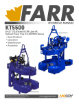
Figure 4-2. 200AS Parts Drawing
(with optional 316 stainless steel case)
12
Table 4-2. 200AS Parts List
Item
1
2
3
4
5
6
7
8*
9*
10
Description
Part No.
DIFFERENTIAL PRESSURE UNIT (NOT SHOWN)
SEE DPU
MANUAL
9A-S961-0042C
9A-S961-0036C
9A-0226-0020B
9A-0129-1012T
9A-0288-0028C
9A-0226-0023B
9A-0003-0062K
9A-0117-0012J
9A-S961-0051C-1
MOUNTING PLATE, STAINLESS STEEL
CASE, INDICATOR, STAINLESS STEEL
LINK ASSY.
MOVEMENT ASSY.
BRACKET, STOP
DRIVE ARM ASSY.
WASHER, SPLIT LOCK, #4, STAINLESS STEEL
SCREW, BIN. HD., 4-40 x 3/16", SST
SCALE PLATE, ALUMINUM
(DIV./UNITS SPECIFIED)
11 SCREW, SCALE PLATE, FIL HD. 4-40 X 3/16"
12 SNUBBER, POINTER, RUBBER
13* POINTER ASSY., ALUMINUM:
BLACK
WHITE
14 BEZEL
15 LENS
16 GASKET, LENS, RUBBER
17 NOT USED
18 SCREW, BEZEL, ISO M5 C/SUNK DOMED HD.,
STAINLESS STEEL
19* CALIBRATION KIT (NOT SHOWN)
20 SCREWS, CASE MOUNTING, 10-32 UNC, STEEL
(NOT SHOWN)
21 BRACKET, SPACER PLATE, STAINLESS STEEL
22 SCREW, CAP. BRACKET, SPACER PLATE, 1/4
UNC, STEEL (NOT SHOWN)
23 RING, FLANGE, THREADED, STAINLESS STEEL
* Recommended spare parts.
9A-0114-0023J
9A-0226-0028C
Per
Unit
1
1
1
1
1
1
1
2
3
1
4
2
1
9A-0288-0031B
9A-0288-0030B
9A-S961-0037C
9A-S961-0038C
9A-S961-0039C
1
1
1
9A-S961-0041C
9
9A-0288-1032B
9A-0240-0019J
1
4
9A-S961-0044C
9A-0240-0009J
1
4
9A-S961-0040C
1
WARNING
Use only spare parts identified in this manual. Cameron bears no legal responsibility for the performance of a product that has been serviced or repaired with
parts that are not authorized by Cameron.
13
SECTION 5 - install/dimensional drawings
14
15
Product Warranty
A. Warranty
Cameron International Corporation ("Cameron") warrants that at the time of shipment, the products manufactured by Cameron and sold hereunder will be free from
defects in material and workmanship, and will conform to the specifications furnished
by or approved by Cameron.
B. Warranty Adjustment
(1) If any defect within this warranty appears, Buyer shall notify Cameron immediately.
(2) Cameron agrees to repair or furnish a replacement for, but not install, any product which within one (1) year from the date of shipment by Cameron shall, upon
test and examination by Cameron, prove defective within the above warranty.
(3) No product will be accepted for return or replacement without the written
authorization of Cameron. Upon such authorization, and in accordance with
instructions by Cameron, the product will be returned shipping charges prepaid
by Buyer. Replacements made under this warranty will be shipped prepaid.
C. Exclusions from Warranty
(1) THE FOREGOING WARRANTY IS IN LIEU OF AND EXCLUDES ALL OTHER
EXPRESSED OR IMPLIED WARRANTIES OF MERCHANTABILITY, OR FITNESS
FOR
A PARTICULAR PURPOSE, OR OTHERWISE.
(2) Components manufactured by any supplier other than Cameron shall bear only
the warranty made by the manufacturer of that product, and Cameron assumes no
responsibility for the performance or reliability of the unit as a whole.
(3) "In no event shall Cameron be liable for indirect, incidental, or consequential damages nor shall the liability of Cameron arising in connection with any products sold
hereunder (whether such liability arises from a claim based on contract, warranty, tort,
or otherwise) exceed the actual amount paid by Buyer to Cameron for the products
delivered hereunder."
(4) The warranty does not extend to any product manufactured by Cameron which has
been subjected to misuse, neglect, accident, improper installation or to use in violation
of instructions furnished by Cameron.
(5) The warranty does not extend to or apply to any unit which has been repaired or
altered at any place other than at Cameron's factory or service locations by persons
not expressly approved by Cameron.
Product Brand
Barton® is a registered trademark of Cameron International Corporation
("Cameron").
MEASUREMENT SYSTEMS
Formerly: NuFlo Measurement Systems • Barton Instrument Systems • Caldon, Inc.
HOUSTON
HEAD OFFICE
ASIA
PACIFIC
281.582.9500
+603.2287.1039
[email protected]
NORTH
AMERICA
EUROPE,
MIDDLE EAST
& AFRICA
1.800.654.3760
[email protected]
+44.1243.826741
[email protected]
USA • CANADA • UK • SCOTLAND • CHINA • UAE
A L G E R I A • M A L A Y S I A • S I N G A P O R E • www.c-a-m.com/flo