1
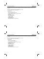
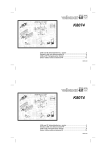
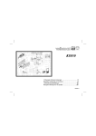
Total solder points: 107
Difficulty level: beginner 1
2
3
4
5
advanced
USB to RF remote control transmitter
K8074
werful
r into a po
te
u
p
m
o
c
Turn your
ntrol
remote co
ILLUSTRATED ASSEMBLY MANUAL
Total solder points: 107
Difficulty level: beginner 1
2
3
4
5
H8074IP-1
advanced
USB to RF remote control transmitter
K8074
werful
r into a po
te
u
p
m
o
c
r
Turn you
ntrol
remote co
ILLUSTRATED ASSEMBLY MANUAL
H8074IP-1
Features & Specifications
The transmitter works together with our K8056 card, equipped with an RX433N receiver module. Also our K8070 / VM119
one channel receiver can be used. In total a combination of 255 cards can be addressed, resulting in a maximum of 2040
channels !!
Drivers and example software can be downloaded from our web site.
A DLL is provided to create your own application.
Specifications:
USB1.1 or 2.0 port compliant
up to 30m (depends on environment)
works with K8056 (+RX433N), K8070 / VM119, VM151, ...
RF transmit indicator LED
power LED
USB port function LED's
255 selectable addresses
transmit—test button
433MHz transmitter
R&TTE compliant design
power supply: USB
dimensions: 80x55x35mm / 3,14x2,16x1,37"
2
Assembly hints
1. Assembly (Skipping this can lead to troubles ! )
Ok, so we have your attention. These hints will help you to make this project successful. Read them carefully.
1.1 Make sure you have the right tools:
•
A good quality soldering iron (25-40W) with a small tip.
•
Wipe it often on a wet sponge or cloth, to keep it clean; then apply solder to the tip, to give it a wet look. This is called ‘thinning’ and will
protect the tip, and enables you to make good connections. When solder rolls off the tip, it needs cleaning.
•
Thin raisin-core solder. Do not use any flux or grease.
•
A diagonal cutter to trim excess wires. To avoid injury when cutting excess leads, hold the lead so they
cannot fly towards the eyes.
•
Needle nose pliers, for bending leads, or to hold components in place.
•
Small blade and Phillips screwdrivers. A basic range is fine.
0.0
00
For some projects, a basic multi-meter is required, or might be handy
1.2 Assembly Hints :
⇒
⇒
⇒
⇒
⇒
⇒
⇒
⇒
Make sure the skill level matches your experience, to avoid disappointments.
Follow the instructions carefully. Read and understand the entire step before you perform each operation.
Perform the assembly in the correct order as stated in this manual
Position all parts on the PCB (Printed Circuit Board) as shown on the drawings.
Values on the circuit diagram are subject to changes.
Values in this assembly guide are correct*
Use the check-boxes to mark your progress.
Please read the included information on safety and customer service
* Typographical inaccuracies excluded. Always look for possible last minute manual updates, indicated as ‘NOTE’ on a separate leaflet.
3
Assembly hints
1.3 Soldering Hints :
1- Mount the component against the PCB surface and carefully solder the leads
2- Make sure the solder joints are cone-shaped and shiny
3- Trim excess leads as close as possible to the solder joint
REMOVE THEM FROM THE TAPE ONE AT A TIME !
AXIAL COMPONENTS ARE TAPED IN THE
CORRECT MOUNTING SEQUENCE !
4
Construction
Break the PCB into 2 pieces
2. Coil
4. Capacitors
L2
L...
L1 : 100µH (1 - 0 - 1 - A)
3. IC socket, Watch the
position of the notch!
1. Resistors
R...
R1
R2
R3
R4
R5
R6
R7
R8
R9
:
:
:
:
:
:
:
:
:
1K
1K
1K
1K
10K
10
10
10
1K
IC1 : 28P
C1
C2
C3
C4
C5
C6
:
:
:
:
:
:
22pF
22pF
10nF
100nF
100nF
220nF
c...
(22)
(22)
(103)
(104)
(104)
(224)
5. Push button
SW1 : Test
6. Electrolytic Capacitor.
Watch the polarity !
(1 - 0 - 2 - B)
(1 - 0 - 2 - B)
(1 - 0 - 2 - B)
(1 - 0 - 2 - B)
(1 - 0 - 3 - B)
(1 - 0 - 0 - B)
(1 - 0 - 0 - B)
(1 - 0 - 0 - B)
(1 - 0 - 2 - B)
C7 : 4,7µF
C...
5
Construction
Break the PCB into 2 pieces
2. Coil
4. Capacitors
L2
L...
L1 : 100µH (1 - 0 - 1 - A)
3. IC socket, Watch the
position of the notch!
1. Resistors
R...
R1
R2
R3
R4
R5
R6
R7
R8
R9
:
:
:
:
:
:
:
:
:
1K
1K
1K
1K
10K
10
10
10
1K
(1 - 0 - 2 - B)
(1 - 0 - 2 - B)
(1 - 0 - 2 - B)
(1 - 0 - 2 - B)
(1 - 0 - 3 - B)
(1 - 0 - 0 - B)
(1 - 0 - 0 - B)
(1 - 0 - 0 - B)
(1 - 0 - 2 - B)
IC1 : 28P
C1
C2
C3
C4
C5
C6
:
:
:
:
:
:
22pF
22pF
10nF
100nF
100nF
220nF
c...
(22)
(22)
(103)
(104)
(104)
(224)
5. Push button
SW1 : Test
6. Electrolytic Capacitor.
Watch the polarity !
C7 : 4,7µF
C...
5
Construction
7. LEDs. Watch the polarity!
LD1
LD2
LD3
LD4
: 3mm RED
: 3mm RED
: 3mm RED
: 3mm RED
'USB'
'USB'
'RX/TX'
'ON'
9. Quartz crystal
X...
X1 : 4MHz
11. IC, watch the position of
the notch!
IC1 : VK8074
programmed PIC18F2450-I/SP
10. Transmitter module
LD...
TX433
CATHODE
Mount the LEDs vertically and
bend so they will be visible
through the window in the
housing.
IMPORTANT : Apply an
extra layer of solder on all
copper PCB tracks.
8. USB connector
For use with VM151 mount
a jumper wire for SK2.
The “ANT” connection will match
the markings on the PCB. Refer
to the illustration or package.
SK1
6
Construction
7. LEDs. Watch the polarity!
LD1
LD2
LD3
LD4
: 3mm RED
: 3mm RED
: 3mm RED
: 3mm RED
'USB'
'USB'
'RX/TX'
'ON'
LD...
CATHODE
9. Quartz crystal
X...
X1 : 4MHz
11. IC, watch the position of
the notch!
IC1 : VK8074
programmed PIC18F2450-I/SP
10. Transmitter module
TX433
Mount the LEDs vertically and
bend so they will be visible
through the window in the
housing.
IMPORTANT : Apply an
extra layer of solder on all
copper PCB tracks.
8. USB connector
For use with VM151 mount
a jumper wire for SK2.
SK1
6
The “ANT” connection will match
the markings on the PCB. Refer
to the illustration or package.
Construction
12. ASSEMBLING THE ANTENNA
IMPORTANT:
Construct the antenna coil as described to make sure it complies with the effective
R&TTE directive.
5mm
10mm
Wind the antenna using the included copper wire.
Remove the lacquer from one side of the wire with a knife so the solder will hold.
Wind the antenna using a Ø 5mm drill bit (NOT 4mm or 6mm).
Make 7 windings and elongate until the antenna is 10mm long (see fig. and picture on the packaging).
Solder the coil in place.
13. TEST
Refer to the user manual *
* Download the user manual from www.vellemanprojects.com
7
Assembly
14. Assembly
- Slide the back panel into the cover
of the housing.
- Install the PCB into the housing.
- Install the window
Close the housing
using the 4 screws.
8
Assembly
14. Assembly
- Slide the back panel into the cover
of the housing.
- Install the PCB into the housing.
- Install the window
8
Close the housing
using the 4 screws.
Schematic diagram
Schematic diagram.
9
Schematic diagram
Schematic diagram.
9
PCB
PCB
10
PCB
PCB
10
www.velleman.be - www.velleman-kit.com
Modifications and typographical errors reserved
© Velleman Components nv. Legen Heirweg 33, 9890 Gavere (Belgium)
H8074IP'1 - 2008 - Rev.1.0
5 410329 377526
www.velleman.be - www.velleman-kit.com
Modifications and typographical errors reserved
© Velleman Components nv. Legen Heirweg 33, 9890 Gavere (Belgium)
H8074IP'1 - 2008 - Rev.1.0
5 410329 377526