1
IVAS TECH
Industrial Vision & Automation Systems
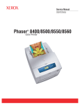
PLM2000
Series
Pick-and-Place Machine
User’s Manual
Revision 1.2
Copyright © 2003 IVAS Tech. All Rights Reserved.
IVAS TECH LTD
15, Tintjava Str. · Sofia 1113 · Bulgaria · Tel: +359 2/ 962 93 85 · Fax: +359 2/ 962 93 86
Web Site: www.ivastech.com
User’s Manual
Page 2
PLM2000 Series Pick-and-Place Machine
Table Of Contents
Changes To User’s Manual ................................................................................ 8
Revision 1.2....................................................................................................... 8
Revision 1.1....................................................................................................... 8
1. Introduction ................................................................................................... 10
2. General Description ...................................................................................... 12
2.1. Software Application Package Overview ................................................ 12
2.1.1 “Pick-and-Place” Program Module.................................................... 12
2.1.2 ''Component Library” Program Module ........................................... 13
2.1.3 “Component Feeder Link” Program Module..................................... 14
2.1.4 “VDF Generator ” Program Module.................................................. 15
2.1.5 “PCB Converter” Program Module ................................................... 15
3. Safety Warning.............................................................................................. 16
4. Hardware Overview...................................................................................... 17
4.1. General ..................................................................................................... 17
4.2. Power Modules......................................................................................... 17
4.2.1. Main Power Switch ........................................................................... 17
4.2.2. Drive Power Module ......................................................................... 17
4.3. Main Air Valve......................................................................................... 18
4.4. Computer System ..................................................................................... 19
4.5 Cooling System ......................................................................................... 19
4.6 Work area .................................................................................................. 19
4.7 XY Positioning System ............................................................................. 20
4.8 Pick-and-Place Head ................................................................................. 21
4.8.1 Internal Camera .................................................................................. 21
4.8.2 View Direction Control Mirrors ........................................................ 22
4.8.3 Lighting .............................................................................................. 22
4.8.4 Nozzle................................................................................................. 22
4.8.5 Z-Distance Sensor (optional) ............................................................. 23
4.8.6 Dispenser (optional) ........................................................................... 23
4.8.7 Soldering Device (optional) ............................................................... 23
4.9 Nozzle Changer ......................................................................................... 23
4.10 Feeder Sockets......................................................................................... 23
4.11 Feeder Support ........................................................................................ 24
4.12 Component Feeders................................................................................. 25
4.12.1 Tape Feeders .................................................................................... 26
4.12.2 Tray Feeders..................................................................................... 29
4.12.3 Stick Feeders .................................................................................... 30
4.13 Manual Operation Switch/Button ........................................................... 31
4.14 Semaphore............................................................................................... 31
4.15 Recycle Bin(s) ......................................................................................... 32
Copyright © 2003 IVAS Tech. All Rights Reserved.
User’s Manual
Page 3
PLM2000 Series Pick-and-Place Machine
4.16 Emergency Stop ...................................................................................... 32
4.17 Machine Cover ........................................................................................ 33
4.18 External Camera (optional) ..................................................................... 33
4.19 Transport (optional) ................................................................................ 34
5. PLM2000 Main Control Module ................................................................. 36
5.1 General Description................................................................................... 36
5.2 Safety Instructions..................................................................................... 37
5.3 PLM2000 Control ..................................................................................... 37
5.3.1 Starting-up.......................................................................................... 37
a. Login Window..................................................................................... 37
b. Initialization Window.......................................................................... 39
5.3.2 Manual Devices Control .................................................................... 40
a. XY Control – Short key Ctrl+1 ........................................................... 40
b. Nozzle Control – Short key: Ctrl+2 .................................................... 40
c. Head Control - Short key: Ctrl+3........................................................ 41
d. Main Control/Transport Control – Short key: Ctrl+4 ......................... 41
e. Dispenser Control (optional) - Short key: Ctrl+6 ............................... 42
f. Soldering Device Control (optional) - Short key: Ctrl+7.................... 43
g. Devices Status Window – Short key: Ctrl+5 ...................................... 44
5.3.3. Camera View Window...................................................................... 45
a. Camera View Modes ........................................................................... 46
b. Camera Devices................................................................................... 46
c. Camera View Status Messages ........................................................... 46
d. Measuring Distances and Angles ........................................................ 46
e. Image Capture History ........................................................................ 47
f. Using Marks......................................................................................... 47
g. Camera Settings .................................................................................. 48
h. Exporting Captured Frame(s).............................................................. 50
5.3.4 Workspace View ................................................................................ 50
a. Machine Working Area ....................................................................... 50
b. Nozzle Changer ................................................................................... 52
c. Tape & Stick Feeders .......................................................................... 52
d. Tray Feeders........................................................................................ 53
5.4 Working with PLM2000 ........................................................................... 55
5.4.1 Parking – Short key: Ctrl+P ............................................................... 56
5.4.2 Teaching Nozzle Changer (Nozzle Source)....................................... 56
5.4.3 Setting Reference Position (Engine Zero) ......................................... 57
5.4.4 Teaching Nozzle Z Reference Position.............................................. 58
5.4.5 Teaching Dispenser Z Reference Position (optional) ........................ 58
5.4.6 Detecting Feeders............................................................................... 59
5.4.7 Creating New PCB ............................................................................. 60
5.4.8 Teaching PCB Start Position.............................................................. 61
5.4.9 Teaching PCB Fiducials..................................................................... 62
Copyright © 2003 IVAS Tech. All Rights Reserved.
User’s Manual
Page 4
PLM2000 Series Pick-and-Place Machine
5.4.10 Teaching/Editing SMD Components ............................................... 63
5.4.11 Adjusting SMD Component Vision................................................. 67
5.4.12 Detecting Fiducials........................................................................... 69
5.4.13 Changing PCB Fiducials .................................................................. 71
5.4.14 Adjusting Fiducial Vision ................................................................ 72
5.4.15 Teaching Feeder Magazine Reference Position............................... 75
5.4.16 Teaching Component Source Position............................................. 76
5.4.17 Saving and Loading PCB Files ........................................................ 78
5.4.18 Multiplying PCB .............................................................................. 78
5.4.19 Rotating PCB ................................................................................... 80
5.4.20 Processes Selection .......................................................................... 81
5.4.21 Running Processes ........................................................................... 83
5.4.22 Feeder Optimization......................................................................... 85
5.4.23 Fiducial Enable/Disable ................................................................... 88
5.4.24 Reloading SMD Components .......................................................... 88
5.4.25 Correcting SMD Positions ............................................................... 89
5.4.26 Including/Excluding SMD Component(s) from Processing............ 89
5.4.27 Changing SMD Value ...................................................................... 90
5.4.28 Deleting SMD Component............................................................... 91
5.4.29 Editing SMD Properties ................................................................... 91
5.4.30 Setting Tray Feeders Pick-up Position............................................. 93
5.4.31 Advancing Tape Feeder Position ..................................................... 94
5.4.32 Dispenser XY Offset Calibration (optional) .................................... 94
5.4.33 Dispenser Reloading (optional) ....................................................... 95
5.4.34 Placing SMD Component Toward Two Points ............................... 97
5.5 Setting Preferences.................................................................................. 100
5.5.1 Dealing With Users and Groups ...................................................... 100
a. Dealing with Groups ......................................................................... 100
b. Dealing with Users ............................................................................ 104
5.5.2 Database Settings ............................................................................. 106
5.5.3 Processes Tuning.............................................................................. 106
5.5.4 Recycle Bins Configuration ............................................................. 108
5.5.5 External Camera Tuning (optional) ................................................. 109
5.5.6 Transport Tuning (optional)............................................................. 110
5.6 Pick-and-Place Statistics ......................................................................... 112
5.6.1 Web Based Statistics ........................................................................ 112
5.6.2 PLM-program Based Statistics ........................................................ 115
5.7 Troubleshooting ...................................................................................... 118
5.7.1 Start-up Problems............................................................................. 118
5.7.2 Machine Stop with Taken Nozzle.................................................... 118
5.7.3 Statistics Do Not Work .................................................................... 118
5.7.4 Absent Electricity............................................................................. 118
5.7.5 Camera Do Not Work Properly ....................................................... 118
Copyright © 2003 IVAS Tech. All Rights Reserved.
User’s Manual
Page 5
PLM2000 Series Pick-and-Place Machine
5.8 User Interface Reference......................................................................... 120
5.8.1 Menus ............................................................................................... 120
a. Pull Down Menus .............................................................................. 120
b. Popup Menus..................................................................................... 125
5.8.2 Toolbars............................................................................................ 130
5.8.3 Status bar .......................................................................................... 133
5.8.4 Manual Control Windows ................................................................ 133
a. XY Control ........................................................................................ 133
b. Nozzle Control .................................................................................. 133
c. Head Control ..................................................................................... 133
d. Main Control/Transport Control ....................................................... 134
e. Dispenser Control (optional) ............................................................. 134
f. Solder Control (optional) ................................................................... 134
g. Device Status Window...................................................................... 134
5.8.5 Camera View Window..................................................................... 134
a. Popup menu ....................................................................................... 134
b. Toolbar .............................................................................................. 136
c. Settings Window ............................................................................... 137
5.8.6 Pick-and-Place View ........................................................................ 138
5.8.7 Preferences Window ........................................................................ 139
5.8.8 Login Window ................................................................................. 139
5.8.9 Devices Initialization Window......................................................... 139
5.8.10 Hotkey Reference........................................................................... 140
6. Component Library .................................................................................... 141
6.1 General .................................................................................................... 141
6.2 Using Library .......................................................................................... 142
6.2.1 Creating New SMD Component ...................................................... 142
a. Creating Component Casing ............................................................. 142
b. Creating Pins ..................................................................................... 144
c. Creating Mark.................................................................................... 145
d. Adding Adhesive Points.................................................................... 146
e. Adding Solder Cream........................................................................ 147
f. Setting SMD Component Properties ................................................. 148
g. Create BGA ....................................................................................... 149
6.2.2 Creating New Feeder..................................................................... 150
a. Creating New Tape Feeder................................................................ 150
b. Creating New Vibro Feeder .............................................................. 151
c. Creating New Tray Feeder ................................................................ 152
6.2.3 Zooming ........................................................................................... 154
6.2.4 Moving Elements ............................................................................. 154
6.3 User Interface Reference......................................................................... 155
6.3.1 Menus ............................................................................................... 155
6.3.2 Toolbar ............................................................................................. 156
Copyright © 2003 IVAS Tech. All Rights Reserved.
User’s Manual
Page 6
PLM2000 Series Pick-and-Place Machine
6.3.3 Status Bar ......................................................................................... 157
6.3.4 Construction Bar .............................................................................. 158
6.4 Standard Components Data..................................................................... 159
6.4.1 Corpus 1206 ..................................................................................... 159
6.4.2 PLCC Components – PLCC 84 ....................................................... 160
6.4.3 QFP – QFP 44 .................................................................................. 161
6.4.4 SO – SO 28....................................................................................... 161
7. Component Feeder Links ........................................................................... 162
7.1 General .................................................................................................... 162
7.2 Using Component Feeder Links Application ......................................... 162
7.2.1 Creating Feeder Magazine ............................................................... 162
7.2.2 Creating Component Feeder Link.................................................... 163
7.2.3 Loading Feeder Magazine................................................................ 165
8. VDF Generator............................................................................................ 167
8.1. General ................................................................................................... 167
8.2. Using VDF Generator ............................................................................ 168
8.2.1 Creating New Vision Data File ........................................................ 168
8.2.2 Using Filters ..................................................................................... 168
8.2.3 Using Recognition Algorithms ........................................................ 170
8.2.4 Setting Region of Interest ................................................................ 172
8.2.5 Adjusting Camera & Light Settings................................................. 172
8.2.6 Setting Recognition Input Parameters.............................................. 174
8.3. User Interface Reference........................................................................ 175
8.3.1 Menus ............................................................................................... 175
8.3.2 Vision Data Bar................................................................................ 177
a. “Camera & Light” ............................................................................. 177
b. Filtering ............................................................................................. 178
b. Analysis............................................................................................. 180
8.3.3 Views................................................................................................ 181
a. Image View ....................................................................................... 181
b. 3D View ............................................................................................ 181
c. Histogram View ................................................................................ 182
8.3.4 Output Bar ........................................................................................ 182
9. PCB Converter ............................................................................................ 184
9.1 General .................................................................................................... 184
9.2 Using PCB Converter.............................................................................. 184
9.3 User Interface Reference......................................................................... 190
9.3.1 Menus ............................................................................................... 190
Appendix A - Image Filters Description ....................................................... 192
A.1 Gaussian Blur ......................................................................................... 193
A.2 Median.................................................................................................... 193
A.3 Median 2................................................................................................. 194
A.4 Median 3................................................................................................. 194
Copyright © 2003 IVAS Tech. All Rights Reserved.
User’s Manual
Page 7
PLM2000 Series Pick-and-Place Machine
A.5 Edge Detect ............................................................................................ 195
A.6 Invert....................................................................................................... 195
A.7 High Pass ................................................................................................ 196
A.8 Low Pass................................................................................................. 197
A.9 Band Pass ............................................................................................... 198
A.10 Notch .................................................................................................... 199
A.11 Contrast Stretch .................................................................................... 200
A.12 Convert to Mono .................................................................................. 201
A.13 Dynamic Threshold .............................................................................. 202
Appendix B - Recognition Algorithms .......................................................... 203
B.1. Rectangular Light Chip ......................................................................... 204
B.2. Four contours......................................................................................... 205
B.3. SOP Recognition ................................................................................... 207
B.4. C0603 Recognition ................................................................................ 208
B.5. QFP Recognition ................................................................................... 209
B.6. BGA Regular Grid................................................................................. 210
B.7. Melf Recognition................................................................................... 211
B.8. T3560 Recognition ................................................................................ 212
B.9. SOT Recognition ................................................................................... 213
B.10. SDC Recognition................................................................................. 214
B.11. Lux Recognition .................................................................................. 215
B.12. FiducialTwoRect ................................................................................. 217
B.13. FiducialTwoRect2 ............................................................................... 218
B.14. Fiducial Circle ..................................................................................... 219
B.15. Fiducial Cross ...................................................................................... 220
B.16. Fiducial Triangle.................................................................................. 221
B.17. BGA 2D Grid Recognition.................................................................. 222
B.18. Coupling1 ............................................................................................ 223
B.19. SOT 23-5 Recognition......................................................................... 224
Copyright © 2003 IVAS Tech. All Rights Reserved.
User’s Manual
Page 8
PLM2000 Series Pick-and-Place Machine
Changes To User’s Manual
Revision 1.2
Added:
• 5.3.4.a. Machine Working Area (page 50) – description of the
coordinate systems used with the machine.
• 5.5.5 External Camera Tuning (page 109) – preferences of the external
camera device.
• 5.5.6 Transport Tuning (page 110) – preferences of the transport
device.
Revision 1.1
Added:
• 5.4.33 Dispenser Reloading (page 95 ) – description of the process of
reloading a dispenser is appended.
• 5.4.34 Placing SMD Component toward two points (page 97) –
description of the configuring and placing SMD component toward
two points.
• Appendix B – Recognition Algorithms (page 203) – following new
recognition algorithms are appended:
o B.15 Fiducial Cross (page 220)
o B.16 Fiducial Triangle (page 221)
o B.17 BGA 2D Grid Recognition (page 222)
o B.18 Coupling1 (page 223)
o B.19 SOT 23-5 Recognition (page 224)
• 5.8.1.b Popup Menus (page 125) - commands for placing component
toward two points are added.
o “PCB” popup menu
“Edit Two Points Position All”
o “SMD Component” popup menu
“Edit Two Points Position”
“SMD Place Two Points”
“SMD Place Two Points On”
“SMD Place Two Points Off”
Revised:
• Appendix B – Recognition Algorithms (page 203)
o Description of the parameters of the recognition algorithms are
appended.
Copyright © 2003 IVAS Tech. All Rights Reserved.
User’s Manual
Page 9
PLM2000 Series Pick-and-Place Machine
• 5.4.20 Processes Selection (page 81)
o Description about the work with one dispenser is appended.
Copyright © 2003 IVAS Tech. All Rights Reserved.
User’s Manual
Page 10
PLM2000 Series Pick-and-Place Machine
1. Introduction
PLM2000 is fully automatic Pick&Place machine built on the base of X/Y
Linear Motors Gantry and CMOS digital camera (1.3 Mpixels) with IEEE 1394
CAN interface for transmission of the video signal. With “On the Fly” video
systems for component and fiducial recognition, PLM2000 is capable of placing
the latest SMT components, such as 0201, 0402 chip components, CSPs, BGAs,
MBGAs PLSSs QFPs. The use of linear motors boosts the work speed and the
placement accuracy. As well as lessens the support and maintenance expenses
PLM2000 can be equipped with 210 of 8 mm feeders as a stand alone model and
120 of 8mm as an In-Line model. The servo motor feeders with built-in
electrical motors carry all package types from 88mm up to 44mm. Due to the
Modular construction of the machine’s body, PLM can be easily upgraded with
a Flexible multi-stage In-Line Transport system to minimize PCB’s handling
time during the production run. PCB's saturation mode PLM2000 is a single
headed machine, while PLM4000 is a double headed one.
The user interface of the machine is based on the well-known WINDOWS
platform. Via a local connection the management staff has access to information
about the production run /saturated PCB’s, number and description of the
assembled components, working and stand-by period, etc/. By default, all
objects e.g. a component or a PCB is clearly displayed on the screen to facilitate
operation and programming and to avoid loss of time due to the adjustment
process. Thanks to the user-friendly interface to operate the machine no
knowledge of the software programs is required.
Integrated into the placement head is a precision 1.3 Mega pixels CMOS
camera with 1394 Fire wire interface for component and fiducial marks
recognition as well for the manual PCB’s teaching process. Due to its
parameters, the operator is able to see the top of the component as well as the
PCB. Its high resolution contributes to the reliable placement of the components
requiring high precision such as BGA, mBGA, LLGA, etc. Via a digital signal
the image of every component to be placed is delivered to a standard PC, which
lessens the “noises” and vibrations of the picture. The connection between the
machine and the PC is controlled via optically isolated CAN interface. The
universal library we created contains component recognition files. A picture the
Pick up position of every component to be placed is compared with the “ideal”
place position and if necessary an automatically alignment operation is
performed.
The component recognizing process is made while Y motion. A small
correction by X-axis is made in the Placing head as well. This way, a precise X
and Y positioning and rotation correction is made while carrying the component
to its place position. A vacuum nozzle picks up the component. Depending on
Copyright © 2003 IVAS Tech. All Rights Reserved.
User’s Manual
Page 11
PLM2000 Series Pick-and-Place Machine
the component’s size/weight different nozzles are available. Z-axis movement
and the rotation are accomplished via servomotors with incremental encoders.
A servo motors system with linear encoders /1 micron accuracy/ and
digital motion controller ensures high speed and precise component placement
process. Linear motors utilization markedly boosts reliability and “life” of the
machine. The high speed and precise positioning ensures placement rate of up to
4200 components per hour.
Due to its unique recognition system, PLM2000 will place any component
from the passives 0201, 0402, Melf, SOT, and SOIC; QFP, PLCC, BGA,
mBGA, LLGA up to 40x40 ICs.
PLM2000 can be equipped with 210 positions of 8mm tape feeders as a
Stand-alone model or 120 positions as an In-Line model.
The tape feeders are servomotor driven with build-in electrical motors,
capable of loading all of the known tapes from 8 mm up to 44 mm.
Waffle tray feeders for up to 2 trays as well as a floating tray feeder
/virtually recognized by the system/ can be loaded on the machine.
100 mm wide vibratory stick feeder allowing of up to 10 lanes of different
adapters is available on request.
The stick feeder adapters are available for all standard components or can
be custom made according to your specifications.
Due to the modular construction of the machine’s body, PLM2000 can be
easily upgraded from a “Stand alone” into an “In-line” model with a flexible,
multi stage Transport system to minimize PCB handling time and optimize the
production process.
The In-line conveyor module offers working heights from 860 up to 970
mm to ensure minimum installation time when connection to the peripheral
equipment. Board sizes from 40x40 mm up to 300x450 mm can be handled on
the In-line conveyor. Right-to-left conveyor module is optional on request.
PLM2000 machines are provided as stand alone and can be configured as
free standing systems, Conveyor module, LDS sensor for automated “set Z”
function, the fine pitch placement reliability as well as the possibility of loading
large amount of feeder lanes makes PLM2000 ideal for contract manufacturers
and OEMs with small to large board sizes and variety of production volumes.
Copyright © 2003 IVAS Tech. All Rights Reserved.
User’s Manual
Page 12
PLM2000 Series Pick-and-Place Machine
2. General Description
2.1. Software Application Package Overview
The software that controls the PLM2000 machines runs on the standard
operating system "WINDOWS" and is based on tree basic modules:
• “Pick-and-Place” program module.
• “Component Library” program module.
• “Component Feeder Link” program module.
There are also three additional modules that are very helpful in the work
with the PLM2000 machines:
• “VDF Generator” program module.
• “PCB Converter” program module.
By default all objects, e.g., a component or a PCB, are clearly displayed
on the screen, to facilitate operation and programming and to avoid
programming errors and loss of time due to adjustment process. The buttons
within the program window are displayed with a function-related symbol. To
operate the software no special knowledge of Microsoft Windows or other
software programs is required.
2.1.1 “Pick-and-Place” Program Module
The “Pick-And-Place” program module is the interface between the
operator and the machine. The production is controlled via the place program.
The total placement area of the system with the feeders, the nozzle rack
including the nozzles and the PCB to be placed, is displayed on the window of
this program module. The program module is used to create, edit and execute
the place programs.
During programming the camera moves to each placement position on the
PCB, and the position as well as the rotation of the component are stored. As the
component is displayed on the screen the placement position can be checked
visually and eventual placement errors can be eliminated. The place data can
also be imported via CAD conversion program.
Copyright © 2003 IVAS Tech. All Rights Reserved.
User’s Manual
Page 13
PLM2000 Series Pick-and-Place Machine
The “Pick-and-Place” Program Module View
For detailed description of the “Pick-and-Place” program module see
Chapter 5. PLM2000 Main Control Module (page 36)
2.1.2 ''Component Library” Program Module
All component data, such as the dimensions and the form of the casings,
the placing stroke, the vacuum as well as the data of the adhesives and the solder
paste dots (dispenser values) is stored in the "Component library" program
module. Each component with its pins and its polarity can be displayed in
accordance with the original of the screen.
Copyright © 2003 IVAS Tech. All Rights Reserved.
User’s Manual
Page 14
PLM2000 Series Pick-and-Place Machine
The “Component Library” Program Module
The most important SMD component types have already been preset at
work. Further components can be programmed at any time via the functions of
the program module.
For detailed description of the “Pick-and-Place” program module see
Chapter 6. Component Library (page 141)
2.1.3 “Component Feeder Link” Program Module
The data of feeders with the corresponding components is stored in
"Component Feeder Link" program module. During the programming the
components can be stored under a specific name.
Copyright © 2003 IVAS Tech. All Rights Reserved.
User’s Manual
Page 15
PLM2000 Series Pick-and-Place Machine
The “Component Feeder Links” Program Module
The component and its pick position in the feeder are displayed
graphically on the screen. Incorrect placements resulting from rotated
components in the feeder are avoided, as the pin №1 or the polarity is displayed
on the screen.
The component type and the corresponding feeder remain stored in the
memory of the machine. If a new feeder is required for the production, the
feeder must be simply installed in the machine. Reprogramming is not
necessary.
For detailed description of the “Pick-and-Place” program module see
Chapter 7. Component Feeder Links (page 162)
2.1.4 “VDF Generator ” Program Module
“VDF Generator” program module is created to help in the creation and
configuration of Image Filters and Recognition Algorithms. It can be used
without the PLM2000 machine on a different computer. The program is used for
recognition of objects captured in 256 grey colour images.
For detailed description of the “PCB Converter” program module see
Chapter 8. VDF Generator (page 167)
2.1.5 “PCB Converter” Program Module
“PCB Converter” program module is created for easy and fast conversion
of PCB made in “CAD” system to PCB in PLM2000 software accessible format.
For detailed description of the “PCB Converter” program module see
Chapter 9. PCB Converter (page 184).
Copyright © 2003 IVAS Tech. All Rights Reserved.
User’s Manual
Page 16
PLM2000 Series Pick-and-Place Machine
3. Safety Warning
The following instruction must be observed when you work on the
machine to prevent personal injuries or damage to the equipment.
1. The system is equipped with safety shield and safety covers. Operate
the machine only with the safety shield closed to avoid serious personal injuries
caused by the moving parts of the machine or by the electrical systems.
2. Unlocked safety shield or modified safety function can result serious
personal injuries.
3. Even when the machine is switched-off, dangerous voltages are present
at the power supply cord and at the internal subsystems.
4. Do not use the system for any application other than its intended use.
5. Do not execute any activities or procedures that are not described in
this manual.
Copyright © 2003 IVAS Tech. All Rights Reserved.
User’s Manual
Page 17
PLM2000 Series Pick-and-Place Machine
4. Hardware Overview
4.1. General
The PLM2000 machine consists of several devices organized in systems moving systems, cooling system, vision system and computer system.
4.2. Power Modules
4.2.1. Main Power Switch
The main power switch turns on and off the power of all the systems of
the machine – the moving systems, the cooling system, the vision system and
the computer system. It should be used after the computer system is safely
turned down and the head is parked.
Main Power Switch
4.2.2. Drive Power Module
The machine is controlled via the control electronics, integrated in the
chassis bellow the placement platform and the PCB. The electronics is the
interface between the detectors and the motors of the system and the PC can
contains the current supply as well as the air distribution system.
Copyright © 2003 IVAS Tech. All Rights Reserved.
User’s Manual
Page 18
PLM2000 Series Pick-and-Place Machine
Drive Power Module
4.3. Main Air Valve
The pressure gauge has to be at least 5.5 bars. If this value is not shown,
adjust the air pressure with the air pressure regulator.
The air pressure gauge
Copyright © 2003 IVAS Tech. All Rights Reserved.
User’s Manual
Page 19
PLM2000 Series Pick-and-Place Machine
4.4. Computer System
The computer system consists of personal computer, LCD monitor and
keyboard. It controls all the devices of the PLM2000 machine. Also a statistics
about the work of the machine are stored there.
The Computer System
4.5 Cooling System
The cooling system is necessary because the XY positioning engines
produce a lot of heat and should be cooled to work precisely.
4.6 Work area
PCB support
The PCB support is located in the centre of the machine and consists of a
torsion-resistant robust frame to hold the PCB to be placed. The PCB is inserted
on the front and the left side into two grooves of the PCB support and clamped
on the right and the rear side by two movable, magnetic holders which can be
placed anywhere on the PCB support, depending on the size of the board.
Copyright © 2003 IVAS Tech. All Rights Reserved.
User’s Manual
Page 20
PLM2000 Series Pick-and-Place Machine
Recycle Bin
PCB Support
The Work area
4.7 XY Positioning System
XY Positioning System consists of two linear engines that move the head
by X and by Y-axis.
Y Axis
X Axis
XY Positioning System
Copyright © 2003 IVAS Tech. All Rights Reserved.
User’s Manual
Page 21
PLM2000 Series Pick-and-Place Machine
4.8 Pick-and-Place Head
The head device consists of many devices: Internal camera, lightning,
nozzle stick, z-movement engines, z-distance sensor (optional), dispenser
(optional), soldering device (optional).
The Head
4.8.1 Internal Camera
Mounted in the core of the head, the Internal camera is used to photograph
the SMD components that are arranged and the PCB fiducial marks. It is black
and white camera that can show picture of 1024x1024 pixels. This is the eye of
the PLM2000 machine.
The Internal Camera
Copyright © 2003 IVAS Tech. All Rights Reserved.
User’s Manual
Page 22
PLM2000 Series Pick-and-Place Machine
4.8.2 View Direction Control Mirrors
The camera should be able to take a photo of a SMD component picked
up with a nozzle and of the PCB and the work area that is bellow the head. Thus,
mirrors are used to change the direction of view of the camera - it can be up and
down.
Right Mirror
Left Mirror
View Direction Control Mirrors
4.8.3 Lighting
The lightning consists of one or more frames of red diodes. The lightning
is necessary because when SMD components and fiducials are photographed,
light is needed.
The Lighting – turned on
The Lighting – turned off
4.8.4 Nozzle
The nozzles are picked up by vacuum tips. Depending on the component
size and weight five different pairs of nozzles is available to choose from. The
nozzles and their numbers are shown in the picture below.
Copyright © 2003 IVAS Tech. All Rights Reserved.
User’s Manual
Page 23
PLM2000 Series Pick-and-Place Machine
Nozzles
4.8.5 Z-Distance Sensor (optional)
Z-Distance Sensor is a laser sensor that measures distance from the head
to the surface beneath the head. It is used for automatic detection of the z source
position of a component in a feeder and for other measurements.
4.8.6 Dispenser (optional)
Dispenser is a device that places drops of fluid on a PCB through a
needle. The fluid goes out of the needle pushed by air pressure and Archimedes
screw.
4.8.7 Soldering Device (optional)
Soldering device solders SMD components on a PCB. It moves up and
down pushed by air pressure.
4.9 Nozzle Changer
The nozzles are held in a rack, which is located on the front side of the
PCB support. Locking plate prevents the inadvertent removal of a nozzle. Two
detectors monitor the presence of a nozzle at the corresponding position as well
as the status of the lock (open/closed).
The Nozzles Changer Device
4.10 Feeder Sockets
The communication between the feeders and the computer system is
accomplished through the sockets. They are mounted in the side panels of the
PCB support.
Copyright © 2003 IVAS Tech. All Rights Reserved.
User’s Manual
Page 24
PLM2000 Series Pick-and-Place Machine
Feeder Socket
Feeder Sockets
4.11 Feeder Support
The feeder supports are the mechanical base for the modular feeder
system. They are adjusted with centring pins in the PCB support and locked with
screws on the mounting platform. The exact positioning of the feeder supports is
achieved by centring holes beneath the sockets.
The feeders are inserted in the longitudinal groove of the casing of the
feeder support and the locking groove of the side of the feeders support and
pushed up to the placement position. The feeders are pulled out at a handle
located at the side.
Feeder Support
Copyright © 2003 IVAS Tech. All Rights Reserved.
User’s Manual
Page 25
PLM2000 Series Pick-and-Place Machine
4.12 Component Feeders
The feeders have been especially developed to be quickly exchanged
during a production run. They are microprocessor controlled, so that data of the
components (Component type, pick position etc.) is automatically transferred to
the machine, when the feeder is installed on PLM2000 machine.
If a component type is not found in the configuration when a place
program is loaded, a message will be displayed on the screen.
The feeder with the component required can be installed at any slot. The
machine recognizes the new component type automatically and the production
run can be started. The feeders are installed in feeder cassettes with a standard
width of 100mm. As all-important data is stored in the internal memory of the
feeder, the feeder cassettes can be replenished even during a production run
without having to open the machine.
Installing The Component Feeders On The System:
1. When empty feeder support is available to receive the feeder required
for the production, execute the following steps to remove feeder:
a) To remove a stick feeder, first press the On/Off button to switch
the vibration off.
b) Pull the feeder carefully at the handle of the slide of the feeder
support to the rear and out of the system until stop.
c) Lift the feeder at the handle and remove the feeder out of the
feeder support.
2. If any empty feeder support is available on the system put the slide of
the feeder support on the handle carefully to the rear until stop.
3. Insert the feeder with the component type required in the longitudinal
groove of the feeder support and in the locking groove of the slide.
4. Push the feeder with the slide in the machine until stop. The new
component types are recognized automatically by the electric control of the
system.
Caution:
Before inserting the feeder, remove any components remaining from a
previous production run from the feeder supports.
Caution:
To avoid damaging the pins of the interface connectors do not use any
force when pushing in the feeder cassettes. If the cassette cannot be inserted
until stop, check its position in the feeder support and check the feeder support
for lost components.
5.When further components are required for the production run, repeat
steps 1 through 4.
6. Press the On/Off button to switch the vibration on.
Copyright © 2003 IVAS Tech. All Rights Reserved.
User’s Manual
Page 26
PLM2000 Series Pick-and-Place Machine
The feeders can be replenished when they are installed on the system, or
after they have been removed. To replenish an installed feeder, carefully pull the
feeder out of the system until stop and perform following steps.
Feeder’s Replenishment:
The feeders can be replenished when they are installed on the machine or
even during a production run. When a component could not be picked up from a
feeder after a tree course and a message is displayed on the screen, signal light
illuminates red.
Note: The feeders may only be replenished with the programmed
component type. The assignment of the different component types and the
corresponding feeders is done via lists or via the "Pick-and-Place" program
module.
The following types of feeder are available:
-Tape feeders for tape reels.
-Stick feeder with vibrating unit.
-Static tray feeder.
4.12.1 Tape Feeders
The tape feeders are installed in feeder cassettes. The cassettes can
contain tapes with a uniform width (e.g. 10 tapes of 8mm each), or tapes with a
different width. For example, 3 tapes of 16mm and 3 tapes of 12mm. Tapes of 8,
12, 16, 24 and 32mm are available as a standard. The diameter of the tape reels
(7" or 13") is independent of the tape width.
Tape Feeder
Copyright © 2003 IVAS Tech. All Rights Reserved.
User’s Manual
Page 27
PLM2000 Series Pick-and-Place Machine
The component tape in the cassette is motor driven. The cover tapes are
pulled off automatically and wound up on reels. The feeder of each tape (lane)
and the different lanes are selected via a servo, an encoder and a motor.
Replenishing a tape feeder:
1. Cut off the empty tape directly beneath the tape feeder.
2. Tilt the tensioner of the tape feeder upward and pull the cover tape and
the component tape out of the feeder, as shown on the picture.
3. Remove the cover tape reel out of the feeder
4. Remove the pinion, the cover disk and the spacer with the cover tape.
The pinion and the cover disk are held together with a magnet.
5. Remove the cover tape from the spacer.
6. Remove the empty tape reel with the reel holder out of the feeder.
7. Disassemble the right and the left part of the holder, which are held
together with strong magnets and remove the tape reel.
Copyright © 2003 IVAS Tech. All Rights Reserved.
User’s Manual
Page 28
PLM2000 Series Pick-and-Place Machine
8. Put the new tape reel on the axle of the left reel holder part and put both
reel holder parts together.
9. Insert the reel holder in the feeder and feed the component tape beneath
the cover tape drive roller up to the tape guide.
Guide for Component Tape and Cover Tape.
10. Push the component tape in the tape guide and feed the cover tape
through the deflection slot.
Note:
When the cover tape sticks to the component tape, you can also feed the
cover tape through the component pick opening of the tensioner. Check that the
component is not pulled out of the pick opening due to the electrostatic charging
of the cover tape.
11. Release the tensioner back down. Make sure that the sprocket holes of
the component tape enter into the teeth of the transport wheel.
12. Put the spacer of the axle of the pinion or on the axle of the cover
disk.
13. Put the cover tape from above over the spacer, put it into the metallic
teeth of the spacer, and wind it one or two times round the spacer.
14. Put the cover disk or the pinion on the spacer.
Copyright © 2003 IVAS Tech. All Rights Reserved.
User’s Manual
Page 29
PLM2000 Series Pick-and-Place Machine
15. Insert the cover tape reel in the feeder and tension the cover tape by
winding the cover tape up.
16. Check the pick coordinates of the tape feeder and the orientation of
the component as a pick position. Change the programmed pick coordinates, if
necessary.
4.12.2 Tray Feeders
The tray feeders can receive trays up to maximum size of 170mm 400mm (large tray feeder) and 135mm- 320mm (small tray feeder).
The Small Tray Feeder
The frame and the support plate are adapted to the shape of the feeder
cassettes to ease a quick change of the feeders during production run.
Replenishing a Tray Feeder:
1. Remove the empty tray out of the feeder.
2. Install a new tray in the feeder.
3. Lock the tray with the magnetic holders.
4. Open the “Pick-And-Place” program module.
5. The first position of the tray feeder is always coloured in red.
• To change the pick up position click left mouse button on the
desired box to highlight.
• Click right mouse button and select “Set Pick up Point”. The
pick up position is automatically changed.
6. Make sure that the components on the tray are correctly orientated. A
rotation through 90º, 180º or 270º can result in a faulty placement of the
component.
7. Check the pick coordinates of the first component on the tray. Change
the programmed pick, if necessary.
Copyright © 2003 IVAS Tech. All Rights Reserved.
User’s Manual
Page 30
PLM2000 Series Pick-and-Place Machine
4.12.3 Stick Feeders
The stick feeders are also installed in standard cassettes. Each stick feeder
can be adapted to the stick width desired. The position of the stick in the feeder
is defined by changing the stick support.
The stick feeders have an integrated microcontroller so that they can be
replenished quickly during a production run.
Stick Feeder
The stick feeder is controlled manually via the operating elements on the
operator panel of the feeder. Press the ON/OFF button to switch the feeder On
or Off. The vibration frequency is adjusted with a potentiometer. When the
feeder is switched on, it is the stand-by mode and the vibration can be adjusted
by operating the manual button, or via electric control of the machine. When the
manual button is pressed, the vibration remains active until the button is released
again.
Replenishing a Stick Feeder:
1. To remove a stick feeder, first press the On/Off button to switch off the
vibration
2. Pull the empty component stick carefully to the rear and out of the
feeder.
3. Remove the cover from the new component stick and push the
component stick from the rear into the feeder and into the feeder support until
stop.
4. Press the On/Off button to switch the vibration on.
5. Regulate the vibration with the potentiometer while keeping the yellow
manual button pressed. The components are transported by the vibration up to
the pick position, but may not fall out of the feeder support or are pushed on top
of each other.
6. Check the pick coordinates of the stick feeder and the orientation of the
component at the pick position. Change the pick coordinates if necessary.
Copyright © 2003 IVAS Tech. All Rights Reserved.
User’s Manual
Page 31
PLM2000 Series Pick-and-Place Machine
4.13 Manual Operation Switch/Button
The Manual Operation Switch and the Manual Operation Button are used
when the machine should work with open cover. The most important thing when
working with open cover is to protect the operator from the moving parts of the
machine – the head and the transport. That is why the Manual Operation Button
is used. If the button is not down and the cover is opened the head can be moved
only with hand, not by the machine’s software.
When you work with open machine cover the manual operation button
have to be hold down and the manual operation switch should be turned on
before the button is pressed. If the button is released then the machine will block
all mechanical movements. After the manual operation button has been released,
the manual operation switch has to be turned off and then again turned on. Only
after this the manual operation button can be pressed again and the machine can
continue to work with open cover.
Manual Operation Switch and Button
4.14 Semaphore
The semaphore indicates the status of the machine. Functions of the
semaphore are described hereafter:
GREEN: The green part of the status lamp illuminates when the machine
is in a production run, without need of an operator’s intervention.
YELLOW: When an operator’s interference is required, the status lamp
illuminates with its yellow section. This sector highlights when create a new
initial PCB, multiple PCB, or to teach a PCB.
RED: The system has been stopped due to an error condition. The
production run cannot be continued and an operator action is required. The error
must be eliminated.
Copyright © 2003 IVAS Tech. All Rights Reserved.
User’s Manual
Page 32
PLM2000 Series Pick-and-Place Machine
The Semaphore
4.15 Recycle Bin(s)
Recycle Bin is a metal box where unrecognized components are placed
for recycling. The operator can sort the components and use them again. There
can be as many recycle bins as necessary. The only limitation is the space
needed to place the bins.
Recycle Bin
4.16 Emergency Stop
The “Emergency Stop” button terminates the main power of the machine.
All electric devices stop immediately to function. Press this button in emergency
situations when there is no other way to prevent accident or machine damage.
Do not use this button to stop the machine if there is other way to get out
of the situation, because emergency stop can damage the computer system of the
machine. Also all unsaved information will be lost.
Copyright © 2003 IVAS Tech. All Rights Reserved.
User’s Manual
Page 33
PLM2000 Series Pick-and-Place Machine
The Emergency Stop
4.17 Machine Cover
Machine Cover is intended to protect the operator from injuries caused by
the machine. Operators should never work with opened machine cover.
When the cover is opened and the manual operation button is not down,
all the engines of the machine are turned off. The head can be move only from
the operator manually, not from the machine. Thus, the operator can be sure that
the head will not injure him.
The camera works all the time, also the position of the head can be
reported.
Machine’s Cover
4.18 External Camera (optional)
“External Camera” is used for larger components like BGA, that cannot
be photographed with the “Internal Camera”. Like the internal camera it is black
and white camera and is configured and commanded the same way as the
internal camera.
Copyright © 2003 IVAS Tech. All Rights Reserved.
User’s Manual
Page 34
PLM2000 Series Pick-and-Place Machine
External Camera
4.19 Transport (optional)
The transport moves a PCB automatically inside the machine. Thus, the
operator does not need to open the machine’s cover for every PCB that is
arranged. This saves a lot of time and automates the process – more than one
machine can be joined to form a line.
The transport consists of three segments: input, working and output. The
PCB is taken from the input segment, arranged in the working segment and the
ready PCB is ejected from the third segment. Every segment has its own engine
and can be moved separately. At the left part of every segment there is sensor
that indicates if there is a PCB in the segment. It is important nothing except for
the PCB to cover the sensor. Also the distance between two PCBs should be
enough so that they can be considered as two separate objects. Otherwise the
logic of the transport can be confused.
First (Input) Segment
Third (Output) Segment
Copyright © 2003 IVAS Tech. All Rights Reserved.
User’s Manual
Page 35
PLM2000 Series Pick-and-Place Machine
First
Second
Third
The First, Second (working) and Third Segments
Copyright © 2003 IVAS Tech. All Rights Reserved.
User’s Manual
Page 36
PLM2000 Series Pick-and-Place Machine
5. PLM2000 Main Control Module
5.1 General Description
This module is the connection between the operator and the machine. It is
the way the working process is controlled.
On the screen the whole work area is visualized including the feeders, the
nozzles and the PCB.
The module is used for creation, edition PCB files and execution of
working files – pick and place process and other optional processes. During the
time of programming the “Head” moves and localize the position of every
component on the PCB. Inexact placement of an element is avoided by visually
showing the corresponding position of the component. The programming can
also be done with “CAD Converter”.
The PLM Module View
Copyright © 2003 IVAS Tech. All Rights Reserved.
User’s Manual
Page 37
PLM2000 Series Pick-and-Place Machine
5.2 Safety Instructions
The following instruction must be observed when you work on the
machine to prevent personal injuries or damage to the equipment.
1. The system is equipped with safety shield and safety covers. Operate
the machine only with the safety shield closed to avoid serious personal injuries
caused by the moving parts of the machine or by the electrical systems.
2. Unlocked safety shield or modified safety function can result serious
personal injuries.
3. Even when the machine is switched-off, dangerous voltages are present
at the power supply cord and at the internal subsystems.
4. Do not use the system for any application other than its intended use.
5. Do not execute any activities or procedures that are not described in
this manual.
5.3 PLM2000 Control
5.3.1 Starting-up
To start the “PLM” program, double click on the PLM icon
desktop. PLM Login Dialog will appear.
After this there are two steps before the machine is ready to run:
1. Login process
2. Initialization process
on the
a. Login Window
To be able to operate with the system, every user should use its unique
username and password. Each user belongs to a Group with restricted rights to
do only operations that it should.
Device initialization is the process of configuring all devices to work
properly – engines, controllers and so on. If the initialization is skipped the
machine cannot work as usual because its devices are not configured. This
option is used during calibration from the technicians. They configure and test
the hardware.
Copyright © 2003 IVAS Tech. All Rights Reserved.
User’s Manual
Page 38
PLM2000 Series Pick-and-Place Machine
PLM Login Dialog
Logging into the PLM system:
1. From the “PLM Login” dialog select your user from the list of users (if
you do not have user, contact you supervisor to create one for you and give you
the appropriate rights of access).
2. Enter you password in the “Password” edit box.
3. Press “Login” button to enter the PLM system.
Change you user’s password:
1. From the “PLM Login” dialog select your user from the list of users
2. Enter you password in the “Password” edit box
3. Press “Change” button.
4. Enter the new password and verify it.
Skip Device initialization:
1. From the “PLM Login” dialog select your user from the list of users (if
you do not have user, contact you supervisor to create one for you and give you
the appropriate rights of access).
2. Enter you password in the “Password” edit box.
3. Check the “Skip device initialization” checkbox
4. Press “Login” button to enter the PLM system.
Copyright © 2003 IVAS Tech. All Rights Reserved.
User’s Manual
Page 39
PLM2000 Series Pick-and-Place Machine
Possible Troubles:
1. You do not have user. Contact you supervisor to create one for you and
give you the appropriate rights of access.
2. You cannot login with you password. The password is case sensitive,
so check the “Caps Lock” and the language you are writing in. If still cannot
enter the system contact your supervisor.
IMPORTANT! Do not skip device initialization, if you do not know
exactly what this means. You can seriously damage the machine!
b. Initialization Window
After the login process, the initialization process begins. During this
process all the hardware is checked and configured to work correctly. After this,
all devices are set to their “Home” position and the machine is ready to work.
Results from initialization process are shown in the “Initialization dialog”.
Failures are shown in red. If there is problem with the initialization process
carefully read the error message. Do not press ignore button if you are not sure
what the problem is and how serious it is. If some initializations fail, there is
possibility for hardware problems, so the machine may not run entirely correct.
Initialization dialog
To stop the initialization, press “Cancel” button.
Copyright © 2003 IVAS Tech. All Rights Reserved.
User’s Manual
Page 40
PLM2000 Series Pick-and-Place Machine
5.3.2 Manual Devices Control
With Manual Dialogs you can command and observe the machine devices
at lower lever. There are seven basic Controls, but some of them are optional.
a. XY Control (page 40)
b. Nozzle Control (page 40)
c. Head Control (page 41)
d. Main Control/Transport Control (page 41)
e. Dispenser Control (optional) (page 42)
f. Soldering Device Control (optional) (page 43)
g. Devices Status Window (page 44)
a. XY Control – Short key Ctrl+1
With this control dialog you can move the head of the machine by X and
Y-axes.
Manual XY Control
• “Step” radio box – the distance which the head will move
• “Direction” buttons – the direction in which the head will move
• “0” button – sends the head in the “Home” position.
b. Nozzle Control – Short key: Ctrl+2
With this control you can move the nozzle stick up and down and rotate it
toward the Z-axis. Be very careful not to hit it in the working table. That can
seriously damage the whole machine.
Nozzle Control Dialog
• “Step” radio box – the distance/degrees which the nozzle will move/rotate
toward Z axis
• “Up” and “Down” arrows – moves the nozzle stick up and down.
• “Left” and “Right” arrows – rotates the nozzle clockwise and contraclockwise
Copyright © 2003 IVAS Tech. All Rights Reserved.
User’s Manual
Page 41
PLM2000 Series Pick-and-Place Machine
c. Head Control - Short key: Ctrl+3
With this dialog you can control the prisms (what you see), the air and
vacuum, and the light (the way you see).
Head Control Dialog
• “Activate Prism Left” check box – moves the left prism so that you can
observe the working area beneath the head (where the PCB is placed).
• “Activate Prism Right” check box – moves the right prism so that you can
observe the component that you picked with the nozzle, or the nozzle
itself.
• “Air” check box – switch on and off the air. The air is switched on when
the component is placed at its site on the PCB.
• “Vacuum” check box – switch on and off the vacuum. When vacuum is
switched on a component can be picked up with the nozzle.
• “Light Intensity” – controls the intensity of the light in specific part of the
head. It has four levels, but there are machines that not all levels are
available.
o “Bottom” – controls the intensity of the light from the bottom part
of the head.
o “Top” – controls the intensity of the light from the top part of the
head.
There may be only one light at some heads.
d. Main Control/Transport Control – Short key: Ctrl+4
With this control you command the state of the cover and the nozzles
changer – locked or unlocked. If a transport is attached to the machine it is
commanded with this control.
Main Control Dialog without transport
Copyright © 2003 IVAS Tech. All Rights Reserved.
User’s Manual
Page 42
PLM2000 Series Pick-and-Place Machine
Main Control Dialog with transport
• “Unlock/Lock cover”: Unlock/Lock the cover of the machine when the
check mark is visible/invisible.
• “Unlock/Lock nozzles”: Unlock/Lock the nozzles changer device when
the check mark is visible/invisible.
•
•
•
•
•
Next commands are available only if the machine has a transport
“Lock/Unlock Locker”: Lock/Unlock the locker device when the check
mark is visible/invisible.
“Lock/Unlock Stopper”: Lock/Unlock the stopper device when the
check mark is visible/invisible.
“Move Input”: Moves a PCB from the beginning of the first segment to
its end. The PCB is not moved from the first segment to the second. If
there is no PCB on the segment or the PCB does not move to the output
sensor of the segment, after a timeout the segment will stop to move.
“Move Work”: Moves a PCB from the beginning of the second segment
to its end. The PCB is not moved from the second segment to the third. If
there is no PCB on the segment or the PCB does not move to the output
sensor of the segment, after a timeout the segment will stop to move.
“Move Output”: Moves a PCB from the beginning of the third segment
to its end. The PCB is not moved from the second segment to the third. If
there is no PCB on the segment or the PCB does not move to the output
sensor of the segment, after a timeout the segment will stop to move.
e. Dispenser Control (optional) - Short key: Ctrl+6
Not all machines have dispenser(s) devices, so the Dispenser Control will
not be available if the machine does not have dispenser(s).
With the “Manual Dispenser Control” you command the dispenser
mounted at the head.
Copyright © 2003 IVAS Tech. All Rights Reserved.
User’s Manual
Page 43
PLM2000 Series Pick-and-Place Machine
Manual Dispenser Control Dialog
• “Step” – controls two parameters at the same time:
- the distance that the dispenser will move in Z axis
- the count of turns that the engine of the dispenser that makes the
fluid go out of the squirt will do
• “Active Disp” – activates the one of the dispensers mounted at the
head. If there is only one dispenser that field will be missing.
• “Air control” – controls the air in the dispenser. For the fluid to go out
of the squirt, the air should be turned on.
• “Quantity” indicator – the quantity of fluid, calculated with the
Automatic fluid counting mechanism. If it is not reloaded correctly,
this indicator may show incorrect values.
• “Z Position” indicator – the position at which the dispenser is placed. 0
is the position where the dispenser is safe – the head can be moved.
• “Direction” buttons – controls the Z position of the dispenser and
makes the fluid goes out of the squirt
• “Up” and “Down” arrows – moves the dispenser up and down in Z
direction.
• “Left” and “Right” arrows – makes the engine that makes the fluid
goes out of the squirt to rotate. If you rotate left the fluid will goes out.
If you rotate right the fluid will go inside the squirt.
f. Soldering Device Control (optional) - Short key: Ctrl+7
Not all machines have soldering devices, so the Solder Control will not be
available if the machine does not have solder.
With the “Manual Solder Control” you command the solder mounted at
the head.
Copyright © 2003 IVAS Tech. All Rights Reserved.
User’s Manual
Page 44
PLM2000 Series Pick-and-Place Machine
Manual Solder Control Dialog
• “Activate” check box – moves the solder up and down
• “Solder State” check box array – indicates the position of the solder at
the moment. It can be up, down or moving.
• “Absorber” check box – turns on and of the absorber device
• “Rotate” Left/Right arrow – rotates the solder left/right
• “Rotate” 0 button – rotates the solder to 0 degrees
• “Angle” indicator – shows the angle at which the soldering device is
rotated at the moment
• “Set Temperature” – sets the temperature specified at the temperature
edit box to be the temperature that the solder will aim to maintain.
• “Current Temperature” indicators – indicates the temperature of each
of the soldering device beaks
Be very careful when moving the solder up and down because this can
damage the machine. The solder can maintain high temperature so be very
careful not to touch it at this time. You can be very bad burned!
g. Devices Status Window – Short key: Ctrl+5
It displays the positions of the head, the nozzle, the status of the cover and
the X, Y motors.
Copyright © 2003 IVAS Tech. All Rights Reserved.
User’s Manual
Page 45
PLM2000 Series Pick-and-Place Machine
Devices Status Dialog
• “Current Position”:
X, Y – the position of the head in the plain
Z – the position of the nozzle in Z direction
Angle – the angle at witch the nozzle is rotated
• “Drive Temperature” – the temperature of the solder (if there is such)
• “X Status” – the state of the X engine. For example normal, error and so on
• “Y Status” – the state of the Y engine. For example normal, error and so on
• “Cover” – the state of the cover. It can be closed/opened and if closed it can
be locked or unlocked
5.3.3. Camera View Window
In the “Camera View” window the view from the camera is shown.
Camera View Window
Copyright © 2003 IVAS Tech. All Rights Reserved.
User’s Manual
Page 46
PLM2000 Series Pick-and-Place Machine
a. Camera View Modes
Live view – the image in the Camera View window is updated as fast as
possible depending on the size of the image and the exposure time.
Capture – the image in the Camera View window shows the last image
that is captured with the camera.
b. Camera Devices
There can be two cameras on a machine – internal and external.
The internal camera is placed into the head of the machine. With it we
snapshot the components before we place them on the PCB and the PCB.
The external camera is optional. We use it to snapshot bigger components
that cannot be positioned in the focus of the internal camera.
Select the camera device to be used:
1. Right mouse button click over the Camera View window. From the
context menu select Device->Camera Device #0 for the internal camera or
Device->Camera Device #1 for the external camera.
2. The picture in the Camera View window will change if the camera
device you selected differs from the previously selected camera.
c. Camera View Status Messages
Colour measurement – “Pixel intensity at cursor”. In the left-bottom
corner of the screen you the value of the pixel under the mouse pointer is shown.
“Pixel intensity at cursor: 255” in the example.
Position of the head is shown in the right-upper corner of the Camera
View window. “Position: 231.60, -309.63” in the example
d. Measuring Distances and Angles
In the Camera View window you can measure the distance between two
points and the angle between a line across them and the X-axis.
In the left-upper corner you can see the information about the two points
you have selected last.
• Coordinates of the first point – “From: [227.38, -313.29]”
• Coordinates of the second point - ”To: [228.49, -313.34]”
• Distance between the two points in millimetres – “Distance: 1.11”
• Distance between the two points per X axis in mm – “dX: 1.11”
• Distance between the two points per Y axis in mm – “dY: 0.04”
In the right-bottom corner of the Camera View window you can see the
angle between a line across them and the X-axis.
• Angle between the two points in degrees – “Angle: -2.29deg”
Copyright © 2003 IVAS Tech. All Rights Reserved.
User’s Manual
Page 47
PLM2000 Series Pick-and-Place Machine
To measure the distance and angle between two points:
1. Click the “Set First Coordinate” push button
from the Camera
View Toolbar.
2. Left mouse button click over the Camera View where the first point
will be placed. Yellow cross will appear at the point where you have clicked.
3. Click the “Set Second Coordinate” push button
from the Camera
View Toolbar.
4. Left mouse button click over the Camera View where the second point
will be placed. Yellow cross will appear at the point where you have clicked.
5. You can see the data for the two points you marked.
e. Image Capture History
Every image that is captured is stored in a buffer. That way, every
moment you can see the last 10 images.
This is very useful option when a component is not recognized. You can
select the image from the list and analyze why the component have not been
recognized.
Select Recent Image:
1. From the Camera View toolbar select “Select Recent Image”. From the
menu select the image you want to see in the Camera View window
f. Using Marks
The Mark is a circle/rectangle drawn in the centre of the image. It helps
you to adjust an object in the centre of the image very precisely.
You can specify the colour, the size and the type of the mark.
Configure a mark:
1. Select the type of the mark – from the Camera View toolbar select
“Change Camera View Mark Type”. From the menu select Circle or Rectangle
Copyright © 2003 IVAS Tech. All Rights Reserved.
User’s Manual
Page 48
PLM2000 Series Pick-and-Place Machine
depending on the shape of the object you want to adjust at the centre of the
image.
2. From the Camera View toolbar select “Change Camera View Mark
properties”. The following menu will appear
3. Enter the Width and Height of the object you want to adjust at the
centre of the image.
4. Click on the coloured band and select a colour.
g. Camera Settings
The settings of the camera are of enormous importance for getting good
quality image. Incorrect camera settings may result in wrong recognition of the
object, bad quality of the image and other unwanted situations.
“Camera Settings” Window
Exposure – this is the time the photo sensitive matrix of the camera is
exposed to the incoming light. This means that the bigger the Exposure is the
brighter is the image (from 1 to 10000, where each unit is 1/10 of the
millisecond).
Mono Gain – increases the value of the pixels in the entire image with the
specified constant (form 0 to 192).
Copyright © 2003 IVAS Tech. All Rights Reserved.
User’s Manual
Page 49
PLM2000 Series Pick-and-Place Machine
Gamma – multiplies the value of every pixel of the image with constant,
thus changing the contrast levels of the image (from –15 to 15).
Sub Window - the rectangle that the camera sends to the software to be
further analyzed. The idea is that if the window is bigger it is slower captured
and slower transferred. So the smallest possible window should be chosen for
each object that is captured. You can specify its width and height.
Adjust the Camera Settings:
1. Configure the power of the light. You can do this with the Manual
Head Control. The typical value for the light is Bright.
2. Configure the Gamma. Its typical value is 1. Use other value only when
you intentionally want the image to be brighter or dimmer.
3. Shrink the rectangle of the image (width and height) so that the whole
object is visible. Next extend the rectangle little because if the object is not at
the centre of the image, the whole object still should be visible in the image.
Note: As smaller the frame is as faster the image is captured and the
recognition time is lower. So set the smallest possible rectangle.
4. Decrease Mono Gain to zero.
5. Change the Exposure until you reach the desired brightness of the
image. If you reach the maximum exposure and you still do not have the needed
brightness increase the Mono Gain
Recommended brightness:
The object we want to see should not have its all area filled with pixels
that have value of 255. If that is the situation, we have hyper-exposure.
Recommended
NOT Recommended
Recommendations for the camera settings:
1. Mono Gain should be as small as possible.
2. The size of the frame should be as small as possible.
Copyright © 2003 IVAS Tech. All Rights Reserved.
User’s Manual
Page 50
PLM2000 Series Pick-and-Place Machine
3. The value of Gamma should be around 1
h. Exporting Captured Frame(s)
You can export images captured with the camera for other programs. Thus
further processing can be applied over an image.
Export frame to the VDF Generator
1. Right mouse button click over the Camera View Window. From the
popup menu select “Export”
2. From the “Export” menu select the command you want to execute.
• “Send Frame to VDF Generator”: Opens the VDF Generator
program and sends the current frame to it.
• “Send Camera Settings to VDF Generator”: Opens the VDF
Generator and sends the camera settings to it.
• “Save Current Frame to Disk”: Save the current frame to a file.
A dialog will appear and ask you for the name of the file.
• “Dump Image Slots to Disk”: Save all image slots to files.
• “Auto save every captured frame”: All frames captured with the
camera are saved in the “Capture” directory. That is an easy way to
see what is wrong with recognition algorithm and why so many
components co to the Recycle Bin.
5.3.4 Workspace View
a. Machine Working Area
This is the area where the head of the machine can move – including the
feeders, the PCB, the nozzles and the feeder trays.
Copyright © 2003 IVAS Tech. All Rights Reserved.
User’s Manual
Page 51
PLM2000 Series Pick-and-Place Machine
Device Coordinates – the coordinates in the Device Coordinate System
(in millimeters). Device coordinates are used only in the “Device Status” Dialog
and in the “Camera View” Dialog to represent the position of the head.
Logical Coordinates – the coordinates in the Logical Coordinate System
(in millimeters). Logical coordinates are used to represent the position of the
head when we work with positions of PCBs, fiducials, components, feeders –
that happens when we teach, detect or change the position of an object. Starting
position of the PCB ,the positions of the feeders and nozzles are kept in logical
coordinates. Positions of fiducial and SMD components are kept in PCB
coordinates (note that when we set a fiducial or teach a SMD component, we see
the position of the head, not the position of the object).
Copyright © 2003 IVAS Tech. All Rights Reserved.
User’s Manual
Page 52
PLM2000 Series Pick-and-Place Machine
PCB Coordinates – the coordinates in the PCB Coordinate System (in
millimeters). Positions of the fiducials and SMD components are kept in PCB
coordinates. When we use the coordinates of the SMD components for real
coordinates (toward the logical coordinate system origin) we recalculated them
to reflect the real position of the PCB (this position is determined by the
detected positions of the fiducials).
• Machine Reference Position: the position where the X axis and Y-axis of
the XY movement engines’ coordinate system cross, the beginning of the XY
movement engines c. s. It is situated at the left far corner of the machine.
• PCB Position: the position where the logical coordinate system begins. It is
situated at the near left corner of the work area, looked from the position in
front of the monitor. X-axis increases from left to right, and Y-axis increases
from you to the farther corner of the work area.
b. Nozzle Changer
Nozzles are held in a mechanical device called “Nozzle Changer”. It has a
visual representation in the Machine Working Area. Nozzles are black filled
circles. You can take them, leave them, lock and unlock the nozzle changer.
Nozzle Changer
c. Tape & Stick Feeders
The Feeder is the device where the components are picked up from and
then are place on the PCB. We call “Magazine” the undividable device that can
hold definite number of tapes. Each tape we call feeder. So on the picture bellow
you can see a magazine with three feeders in it. Means that there are three tapes
with components and each is separately moved and reloaded.
The difference between a tape and a stick feeder is only hardware, so the
visual representation of the two types of feeders is almost the same.
Copyright © 2003 IVAS Tech. All Rights Reserved.
User’s Manual
Page 53
PLM2000 Series Pick-and-Place Machine
Tape Feeder
d. Tray Feeders
Tray Feeders are places where components can be arranged. They are
used as a position from which we can pickup components and place them on a
PCB. In every tray feeder there can be more then one panel with different
components. We have two trays – standard and extended but in each tray you
can put as many panels as possible.
• Standard Tray Feeder
It is placed at the location of four tape feeders. The exact position is
configurable. You can see how two panels are placed in the standard tray.
Standard Tray Feeder
• Extended Tray Feeder
It can be placed at every possible position in the machine area.
Copyright © 2003 IVAS Tech. All Rights Reserved.
User’s Manual
Page 54
PLM2000 Series Pick-and-Place Machine
Extended Tray Feeder
Copyright © 2003 IVAS Tech. All Rights Reserved.
User’s Manual
Page 55
PLM2000 Series Pick-and-Place Machine
5.4 Working with PLM2000
There are some common operations that can be done with the machine.
Here is a list of them and for each task, a detailed description.
5.4.1 Parking
5.4.2 Teaching Nozzle Changer (Nozzle Source)
5.4.3 Setting Reference Position (Engine Zero)
5.4.4 Teaching Nozzle Z Reference Position
5.4.5 Teaching Dispenser Z Reference Position (optional)
5.4.6 Detecting Feeders
5.4.7 Creating New PCB
5.4.8 Teaching PCB Start Position
5.4.9 Teaching PCB Fiducials
5.4.10 Teaching/Editing SMD Components
5.4.11 Adjusting SMD Component Vision
5.4.12 Detecting Fiducials
5.4.13 Changing PCB Fiducials
5.4.14 Adjusting Fiducial Vision
5.4.15 Teaching Feeder Magazine Reference Position
5.4.16 Teaching Component Source Position
5.4.17 Saving and Loading PCB Files
5.4.18 Multiplying PCB
5.4.19 Rotating PCB
5.4.20 Processes Selection
5.4.21 Running Processes
5.4.22 Feeder Optimization
5.4.23 Fiducial Enable/Disable
5.4.24 Reloading SMD Components
5.4.25 Correcting SMD Positions
5.4.26 Including/Excluding SMD Component(s) from Processing
5.4.27 Changing SMD Value
5.4.28 Deleting SMD
5.4.29 Editing SMD Properties
5.4.30 Setting Tray Feeders Pick-up Position
5.4.31 Advancing Tape Feeder Position
5.4.32 Dispenser XY Offset Calibration (optional)
5.4.33 Dispenser Reloading (optional)
_5.4.34_Pick-and-Place_Processes5.4.34 Placing SMD Component
Toward Two Points
Copyright © 2003 IVAS Tech. All Rights Reserved.
User’s Manual
Page 56
PLM2000 Series Pick-and-Place Machine
5.4.1 Parking – Short key: Ctrl+P
Parking is the act of moving all the devices in their park positions. This
means positions where it is safe for the device and for the operator to do manual
operations in the space of the machine.
You can park the devices if there is no running process. This means that
while there is Pick and Place process you cannot park the devices. You first
should stop the process and then park.
Invoke the park command from the menu:
1. Select Main->Control->Park
Invoke the park command from the toolbar:
from the toolbar
1. Press the “Park” button
Note: Park the devices every time you open the cover of the machine to
work with the PCB in the machine. Parking is time consuming operation so do
not do it when not necessary.
5.4.2 Teaching Nozzle Changer (Nozzle Source)
Each nozzle has definite position in the nozzle changer. This position can
vary a little. So each nozzle has its own source position where the head takes it
and leaves it from.
Set the Teach Nozzle Changer (set the Nozzle Source position):
1. From the menu, select Settings->Set Nozzle Source (select a nozzle,
right mouse button click and select from the context menu “Set Nozzle Source”)
2. The “Set Real Nozzle – X, Y and Z” dialog and the Camera View
window will appear.
“Set Real Nozzle – X, Y and Z” Dialog
Copyright © 2003 IVAS Tech. All Rights Reserved.
User’s Manual
Page 57
PLM2000 Series Pick-and-Place Machine
3. With the arrows move the head so that the centre of the nozzle is at the
centre of the Camera View Window. Adjust the nozzle exactly at the centre of
its nest with hand.
4. Press the “Enable Z” button. “Z Position” panel is enabled
5. Press “Down” button. The nozzle stick will move about 20-40
millimetres above the nozzle.
6. Looking carefully at the nozzle stick start moving it down with
appropriate step, not to hit the nozzle with the nozzle stick. When the stick is at
about 5 mm above the nozzle, hold the nozzle with hand and continue down
with the stick. Listen and feel if there is any unusual sound, or friction. If there
is, correct the X, Y position with the arrows and try again. The stick should pick
very softly the nozzle.
7. Press “Set Z” button to save the position.
8. Test if the source position of the nozzle is exact and if the nozzle can be
taken softly, without friction and rap.
5.4.3 Setting Reference Position (Engine Zero)
Reference Position (Logical Engine Zero) is the starting point of the
coordinate system toward which the PCB is placed. It is situated at the near left
corner of the work area, looked from the position in front of the monitor. X-axis
increases from left to right, and Y-axis increases from you to the farther corner
of the work area. Also this is the position where the Nozzle Z Reference
Position is set for each nozzle.
Set the Reference Position does the following:
1. From the menu, select Settings->Set Engine Zero XY.
2. “Set Logical Engine Zero” dialog and the “Camera View” window will
appear.
“Set Logical Engine Zero” Dialog
3. Move the head at the position where the Reference Position will be.
4. Press “OK” button
Copyright © 2003 IVAS Tech. All Rights Reserved.
User’s Manual
Page 58
PLM2000 Series Pick-and-Place Machine
5.4.4 Teaching Nozzle Z Reference Position
Nozzle Z Reference Position (Nozzle Engine Z) is the Z position that the
nozzle stick should be, so that the bottom of the nozzle not to touch the work
area, but also to be as down as possible. This position is determined at the
Reference Position, and is unique for each nozzle, because each nozzle has
different height.
To set a Nozzle Z Reference Position:
1. Select a nozzle with the mouse.
2. From the menu, select Settings->Set Nozzle Engine Z.
3. The head will go and take the nozzle you want to teach, if not already
in the nozzle stick. Then it will move to the Reference Position.
4. “Set Nozzle Engine Zero – Z” dialog and “Camera View” window will
appear.
“Set Nozzle Engine Zero – Z” Dialog
5. Press “Down” button to move the stick fast down
6. Place very thin sheet (nylon or some other material, 0.3-0.5mm) under
the nozzle stick with the nozzle in it and move down the nozzle until the sheet
moves really hard under the nozzle.
7. Press “OK” button
Note: First set the Reference Position, next the Nozzle Source Positions
and last the Nozzle Z Reference Position.
5.4.5 Teaching Dispenser Z Reference Position (optional)
This operation is available only on machines where dispenser is mounted.
Dispenser Z Reference Position is the Z position that the dispenser should
be, so that the down end of needle not to touch the work area, but also to be as
Copyright © 2003 IVAS Tech. All Rights Reserved.
User’s Manual
Page 59
PLM2000 Series Pick-and-Place Machine
down as possible. This position is determined at the Reference Position, and is
unique for each dispenser. It should be calibrated every time new needle is
placed or the dispenser is removed for cleaning or repair.
Set the Dispenser Z Reference Position:
1. From the menu select Main->Control->Dispenser Commands->Set
Flux/Glue Dispenser Z Zero
2. “Set Z Zero” dialog and “Manual Dispenser Control” dialog will
appear. Also the head will move to the Reference Position.
“Set Z Zero” Dialog
3. Place very thin sheet (nylon or some other material, 0.3-0.5mm) under
the dispenser’s needle and move down the dispenser with the “Manual
Dispenser Control” dialog until the sheet moves really hard under the needle.
4. Press “Set” button to accept the position or “Close” to cancel the
operation.
5. The dispenser will move to its home position.
Note: This operation should be done after every change of the needle of
the dispenser.
5.4.6 Detecting Feeders
Feeders Detection is the process of checking on which sockets Feeder
Magazines are attached and visualization of this magazines. This process starts
automatically each time a Pick-and-Place process starts or a PCB file is opened.
You also can manually start the process to update the view of the workspace
area.
Detecting Feeders:
1. From the menu, select Feeder->Detect Feeders.
2. Only feeders that are attached on the machine will appear at the view.
3. If there are any components that should be placed but are not loaded at
any feeder the “Unloaded SMD Components” dialog will appear.
Copyright © 2003 IVAS Tech. All Rights Reserved.
User’s Manual
Page 60
PLM2000 Series Pick-and-Place Machine
4. If there are components that are loaded more then once the “More than
once time loaded SMD components” dialog will appear.
Note: “Unloaded SMD Components” dialog and “More than once time
loaded SMD components” dialog are intended to help the operator find possible
mistakes – for example wrong taught component, not loaded components that
should be placed and so on.
5.4.7 Creating New PCB
PCB file is the place where all the data for a PCB is stored. This includes:
the properties of the PCB itself – size, fiducial marks, multiplied and so on,
information about the positions and vision files of all components on the PCB,
information about the processes that should be applied over each component.
Create New PCB Board:
1. From the menu, select File->New PCB Board. The “PCB parameters”
dialog will appear.
“PCB parameters” Dialog
2. Enter the physical sizes of the PCB
Data for an initial PCB
Copyright © 2003 IVAS Tech. All Rights Reserved.
User’s Manual
Page 61
PLM2000 Series Pick-and-Place Machine
-PCB “Width”-70.54mm
-PCB “Height”-61.47mm
-PCB “Thikness”-0.9mm
3. Press “Set Start Point” button. The head will move to the “Reference
Position” and the “Teaching PCB Start Position” (see page 61) process will
begin.
4. Press “Set Fiducials” button. The “Teaching PCB Fiducials” (see page
62) process will begin.
5. To enable automatic fiducial detection, check the “Auto Fiducial”
check box.
6. Press “OK” button in the “PCB parameters” dialog to end with the
creation of the PCB.
7. Save the PCB. From the menu select File->Save and select appropriate
name for the PCB you have just created.
5.4.8 Teaching PCB Start Position
“PCB Start Position” is a position, situated comparatively in the ultimate
left angle of each PCB and is relative with the “0” point of machine’s head in
the front of PCB support.
Teaching PCB Start Position:
1. “Set Start Point” dialog and “Camera View” dialog will appear.
“Set Start Point” Dialog
Copyright © 2003 IVAS Tech. All Rights Reserved.
User’s Manual
Page 62
PLM2000 Series Pick-and-Place Machine
2. With the “X, Y Move” buttons move the head at the “PCB Start
Position”. You can control the movement step per button click by “X, Y Step”
radio buttons.
3. Press “OK” button.
5.4.9 Teaching PCB Fiducials
A fiducial is a special mark on the PCB that is used for fine corrections of
the positions of the components on a PCB. On every PCB there should be two
fiducial marks that are enough to calculate the corrections that should be done
over the positions and angles of the components placed through the Pick and
Place process.
Teaching PCB Fiducials:
1. The “Set First Fiducial Mark” dialog and the “Camera View” dialog
will appear.
“Set Fiducial Mark” Dialog
2. With the “X, Y Move” buttons move the head at the centre of the first
fiducial. You can control the movement step per button click by “X, Y Step”
radio buttons. If you want to use Auto Fiducial detection press “Adjust Vision”
button and configure the vision of the fiducial.
3. Press the “OK” button.
4. The “Set Second Fiducial Mark” dialog will appear. It is the same as
the “Set First Fiducial Mark” dialog and you set it the same way as the first
mark.
5. Press “OK” button of the “Set Second Fiducial Mark” dialog to finish.
Copyright © 2003 IVAS Tech. All Rights Reserved.
User’s Manual
Page 63
PLM2000 Series Pick-and-Place Machine
5.4.10 Teaching/Editing SMD Components
SMD Components are the elements that the machine pick-up and then
place on the PCB. The process of teaching SMD Component is defining the
exact position of each SMD Component over the PCB.
Teach SMD Component:
1. Right mouse button click over the PCB. The context menu will appear.
Select “SMD Links List” to select from all available created components on the
computer, or select “SMD Feeder List” to select only from the components that
are loaded in the moment.
Context menu for PCB
2. If at the previous step you have selected “SMD Links List”, the
“Loaded SMD Components” window will appear and you will be able to select
from all components that are available at the computer. Otherwise, if at the
previous step you have selected “SMD Feeder List”, the “All Component Feeder
Links” window will appear and you will be able to select only among the
components that are loaded in a feeder in the moment. The two windows offer
the same functionality.
Copyright © 2003 IVAS Tech. All Rights Reserved.
User’s Manual
Page 64
PLM2000 Series Pick-and-Place Machine
“Loaded SMD Components” Window
“All Component Feeder Links” Window
3. Select the component you want to teach with left mouse button click
over its name in the list of components.
4. Select the “Teach SMD” radio button
5. Click “Execute”.
6. The “Set Real Destination – X, Y and Angle” dialog and “Camera
View” window will appear.
Copyright © 2003 IVAS Tech. All Rights Reserved.
User’s Manual
Page 65
PLM2000 Series Pick-and-Place Machine
“Set Real Destination – X, Y and Angle” Dialog
7. With the “X, Y Move” buttons move the head at the position over the
PCB where the component should be placed. You can control the movement
step per button click by “X, Y Step” radio buttons.
8. Enter “Reference” label for the component. This label is shown when
you select the component with the mouse. It is for your facilitation.
NOTE: You can hide/show the corpus and the pins of the component you
are teaching.
9. If the component if rotated in the PCB enter that angle in the “Angle in
PCB” box.
10. Select which processes should be run over the component – some kind
of dispensing, pick and place and soldering.
11. Press “OK” button. The component will be displayed on the display
screen of the PCB as placed and the component data will be saved.
12. When the component have been placed, you can select another
component, or to continue placing the same component somewhere else. So you
will be asked to place the component at other place. If you answer “Yes”, the
same process will go over again. If you select “No”, you can select another
component to teach.
Copyright © 2003 IVAS Tech. All Rights Reserved.
User’s Manual
Page 66
PLM2000 Series Pick-and-Place Machine
Teach SMD Component from the feeder:
1. Select the feeder where the component is loaded.
2. Right mouse button click over the feeder. The “Feeder” popup menu
will appear.
3. From the menu select “Teach SMD Component”.
4. Follow the steps in Teach SMD Component (the step-by-step
description above) starting from step 6.
Edit SMD Component Position:
1. Left mouse button double click over the component, which you want to
edit. Select the component. The “View Real Destination Point” dialog will
appear.
Copyright © 2003 IVAS Tech. All Rights Reserved.
User’s Manual
Page 67
PLM2000 Series Pick-and-Place Machine
“View Real Destination Point” Dialog
2. With the “X, Y Move” buttons move the head at the new position of the
component. You can control the movement step per button click by “X, Y Step”
radio buttons.
3. Change the “Reference” of the component if necessary.
4. Change the orientation of the component and the processes that will be
applied over it.
5. Press “OK” button to finish the editing of the component.
5.4.11 Adjusting SMD Component Vision
Adjusting SMD Components’ Vision is the process of configuring the
camera settings, image filters, and recognition algorithm in such a way that the
component position and rotation can be measured automatically and accurately.
The process is sometimes slow and hard, but this is the only way components
can be placed accurately and without human intervention. Well-adjusted
Component Vision means perfectly arranged PCBs and little discarded
components.
Adjust SMD Component Vision:
Copyright © 2003 IVAS Tech. All Rights Reserved.
User’s Manual
Page 68
PLM2000 Series Pick-and-Place Machine
1. Select the component, which Vision you want to adjust and right click
with the mouse over the selected component (the component may be placed on
PCB or may be in a feeder, there is no matter). The popup menu will appear.
Feeder popup menu
SMD Component popup menu
2. Select Adjust SMD Vision form the context menu. The head will go
and take the appropriate nozzle (if not already taken) and will to the feeder
where the component is loaded. Then a component will be picked up and it will
be shown in the “Camera View” dialog.
Note: The component has to be loaded into a Feeder and it has to have
valid pick up position – X, Y and Z.
3. “Adjust Component Vision” dialog will appear.
Adjust Component Vision Dialog
Copyright © 2003 IVAS Tech. All Rights Reserved.
User’s Manual
Page 69
PLM2000 Series Pick-and-Place Machine
4. Select the appropriate Vision Data File from the list that will appear
when you click on the arrow in the Vision Data File Name combo box –
“lux.vdf”.
5. Press “Camera settings” button. The dialog with settings of the camera
will appear.
6. Press “Filter configuration” button. The dialog with settings of the
filters will appear.
7. Press “Analysis settings” button. The dialog with settings of the
analysis will appear.
8. Press “Test vision data” button. The vision file will be run over the
image of the component captured with the camera in that moment.
9. It is good practice to test the Vision with at least two or three
components to be sure it works correct. So press “Pick new sample” button. The
currently picked up component will be placed in a Recycle Bin and next
component will be picked up from the feeder.
5.4.12 Detecting Fiducials
There are two ways for detection of fiducial marks - automatic and
manual.
In the automatic scenario the head goes over each fiducial mark, takes a
photo of it and tries to recognize it. If the recognition is successful this position
is used where the fiducial’s position is needed. At the end of the process, head
goes to every unrecognized fiducial and waits for the user to manually adjust its
position.
In the manual scenario the head goes over each fiducial mark, and leaves
the operator manually correct the position of the fiducial. It is slower than the
automatic detection, so use the manual detection only if there is no other way.
Automatic Fiducial detection:
1. From the menu, select PCB->Detect Fiducial Marks.
2. The head goes over each fiducial mark, takes a photo of it and tries to
recognize it. If the recognition is successful this position is used where the
fiducial position is needed. During the movement of the head and during the
recognition of the fiducials the “Detecting Fiducial(s)…” dialog will appear.
Copyright © 2003 IVAS Tech. All Rights Reserved.
User’s Manual
Page 70
PLM2000 Series Pick-and-Place Machine
“Detecting Fiducial(s)…” Dialog
3. If there are fiducials that are not recognized the head goes to all of them
one by one and shows the “Detect Fiducials” dialog.
“Detect Fiducials” Dialog
4. With the “XY Control” buttons move the head at the centre of the
fiducial. You can control the movement step per button click by “Step Size”
radio buttons. You can test the recognition algorithm over the fiducial with the
“Test” button or you can adjust the vision file with the “Modify” button.
5. When you are ready with the current fiducial mark press “Next” button
to go to the next fiducial. If you are on the last fiducial mark the “Finish” button
will be enabled and you should press it to apply all detected fiducials.
6. If this is not the last unrecognized fiducial the head will move to the
next unrecognized and the same steps will be repeated. To terminate the fiducial
detection process press “Cancel” button.
Note: If you terminate the fiducial detection process all fiducials that are
detected in the current process will lose their positions.
Copyright © 2003 IVAS Tech. All Rights Reserved.
User’s Manual
Page 71
PLM2000 Series Pick-and-Place Machine
Manual Fiducial detection:
1. From the menu, select PCB->Detect Fiducial Marks.
2. The head goes over the first fiducial marks. The “Detect Fiducials”
dialog will appear.
3. With the “XY Control” buttons move the head at the centre of the
fiducial. You can control the movement step per button click by “Step Size”
radio buttons. If you want to use Auto Fiducial Detection press “Modify” button
and configure the vision of the fiducial. You can also test the vision file over the
fiducial with the “Test” button.
5. Press the “Next” button if this is not the last fiducial to detect.
6. The head will go to the next fiducial and the same steps will be
repeated.
7. When all fiducials are detected the “Finish” button is enabled and you
should press it to apply the positions of the fiducials. To terminate the fiducial
detection process press “Cancel” button.
Note: If you terminate the fiducial detection process all fiducials that are
detected in the current process will loose their positions.
5.4.13 Changing PCB Fiducials
After you configure a PCB and set the positions for the components on
the PCB you may want to change the positions of the fiducial marks. To do this
you first configure the positions of the new fiducial marks and next the positions
of the old fiducial marks. The positions of all components will be calculated
toward the new fiducial marks.
Change PCB Fiducials:
1. Start the “PCB parameters” dialog - from the main menu select PCB>Initial PCB.
2. In the “PCB parameters” dialog click “Set Fiducials” button. The head
will move over the first old fiducial. The “Set First Fiducial Mark” dialog and
the “Camera View” dialog will appear.
Copyright © 2003 IVAS Tech. All Rights Reserved.
User’s Manual
Page 72
PLM2000 Series Pick-and-Place Machine
“Set Fiducial Mark” Dialog
3. With the “X, Y Move” buttons move the head at the centre of the first
new fiducial. You can control the movement step per button click by “X, Y
Step” radio buttons. If you want to use Auto Fiducial detection press “Adjust
Vision” button and configure the vision of the fiducial.
3. Press the “OK” button.
4. The “Set Second Fiducial Mark” dialog will appear. It is the same as
the “Set First Fiducial Mark” dialog and you set it the same way as the first
mark. You should set the second new fiducial.
5. Press “OK” button of the “Set Second Fiducial Mark” dialog to finish
with setting the new fiducials.
6. Click “OK” button of the “PCB parameters” dialog. You will be asked
to detect the old fiducial. Click “OK” to continue with the operation of changing
the fiducials.
7. The head will move over the place where the first old fiducial mark
should be. With the “X, Y Move” buttons move the head at the centre of the first
old fiducial. Click “OK” button.
8. The head will move over the place where the second old fiducial mark
should be. With the “X, Y Move” buttons move the head at the centre of the first
old fiducial. Click “OK” button.
5.4.14 Adjusting Fiducial Vision
Fiducial marks can be recognized automatically – the head goes over each
fiducial mark, take a picture of it and tries to recognize the fiducial. At the end
only unrecognized fiducial marks are left for the operator to adjust them
manually. It is recommended to use Auto Fiducial detection every time it is
possible, because that way the pick-and-place process will be faster.
Copyright © 2003 IVAS Tech. All Rights Reserved.
User’s Manual
Page 73
PLM2000 Series Pick-and-Place Machine
Adjust Fiducial Vision:
1. From the main menu, select PCB->Detect Fiducial Marks. The “Detect
Fiducial Marks” dialog will appear.
“Detect Fiducial Marks” Dialog
2. With the “X, Y Move” buttons move the head at the centre of the first
new fiducial. You can control the movement step per button click by “X, Y
Step” radio buttons.
3. Click “Adjust Vision…” button. The “Adjust Fiducial Vision” dialog
will appear.
“Adjust Fiducial Vision” Dialog
4. Select the appropriate Vision Data File from the list that will appear
when you click on the arrow in the Vision Data File Name combo box –
“Circle1.vdf”.
5. Press “Camera settings” button. The dialog with settings of the camera
will appear.
6. Press “Filter configuration” button. The dialog with settings of the
filters will appear.
7. Press “Analysis settings” button. The dialog with settings of the
analysis will appear.
Copyright © 2003 IVAS Tech. All Rights Reserved.
User’s Manual
Page 74
PLM2000 Series Pick-and-Place Machine
8. Press “Test vision data” button. The vision file will be run over the
image of the fiducial captured with the camera in that moment.
9. Click “Apply” in the “Adjust Fiducial Vision” dialog. Click “OK”
button in the “Detect Fiducial Marks” dialog. The head will move over the next
fiducial mark. Repeat the steps for all fiducial marks on the PCB.
Set Fiducial Vision File:
1. From the main menu, select PCB->Enable/Disable All Marks. The
“Enable / Disable Fiducial Marks” dialog will appear.
“Enable / Disable Fiducial Marks” Dialog
2. In the “Index” column mark all sub PCBs that you want to have own
fiducials, and unmark all sub PCBs that will not have own fiducial marks.
3. For each marked sub PCB set the first fiducial vision file and the
second fiducial vision file:
- Select the sub PCB.
- Click the “Vision File 1” button. The “Vision Data Files” dialog
will appear.
“Vision Data Files” Dialog
Copyright © 2003 IVAS Tech. All Rights Reserved.
User’s Manual
Page 75
PLM2000 Series Pick-and-Place Machine
- Select the Vision Data File you want to use for the recognition of
the first fiducial of the sub PCB.
- Press “OK” button.
- Click the “Vision File 2” button. The “Vision Data Files” dialog
will appear again.
- Select the Vision Data File you want to use for the recognition of
the second fiducial of the sub PCB.
5.4.15 Teaching Feeder Magazine Reference Position
Feeder Magazine Reference Position is the left upper point of the feeder
magazine when you hold the magazine with its face away from you. In the
picture bellow the Feeder Magazine Reference Position is the right-down corner
of the lighted magazine (the magazine is rotated to 180 degrees).
Teach Feeder Magazine Reference Position:
1. Select a Feeder Magazine.
Note: Do not select a tape in the feeder magazine but the whole
Feeder Magazine as shown below.
“Magazine” Popup Menu
2. Right mouse button click over the selected Feeder Magazine. From the
context menu select “Set Feeder Point”. The “Set Real Magazine – X and Y”
dialog will appear.
Copyright © 2003 IVAS Tech. All Rights Reserved.
User’s Manual
Page 76
PLM2000 Series Pick-and-Place Machine
“Set Real Magazine – X and Y” Dialog
3. With the “X, Y Move” buttons move the head the edge of the Feeder
Magazine. You can control the movement step per button click by “X, Y Step”
radio buttons.
4. Press “OK” button.
5.4.16 Teaching Component Source Position
Component Source Position is the position at the feeder where the
component will be picked-up in the pick-and-place process.
Teach a Component Source Position:
1. To define the Component Source Position of a lane, open the safety
shield cover. Turn clockwise the key located on the front left casing of the
machine. Press the red button below the key.
2. Click left mouse-button on the position to be set to highlight.
3. Click right mouse-button to open the “Pop Up” menu.
“Feeder” Popup menu
Copyright © 2003 IVAS Tech. All Rights Reserved.
User’s Manual
Page 77
PLM2000 Series Pick-and-Place Machine
3.Select “Set Feeder X, Y, Z”. The ”Set
Real Source X, Y and Z”
dialog and the “Camera View” window will appear.
“Set Real Source – X, Y and Z” Dialog
4. With the “X, Y Move” buttons move the head at the centre of the
component at the feeder gap. You can control the movement step per button
click by “X, Y Step” radio buttons.
The Camera View Window
5. Press the “Enable Z” button. “Z Position” panel is enabled
Copyright © 2003 IVAS Tech. All Rights Reserved.
User’s Manual
Page 78
PLM2000 Series Pick-and-Place Machine
6. Press “Down” button. The nozzle stick will move about 20-40
millimetres above the component.
7. Looking carefully at the nozzle start moving it down with appropriate
step, not to hit the component with the nozzle. Move down until the nozzle is at
about 1 mm above the component. Then select “Short” for the step of the nozzle.
8. Continue to move the nozzle until it is 0.1-0.2 mm above the
component. Mark the “Vacuum” check box to switch on the vacuum. Look
carefully the component – is it picked up good, is not the nozzle too far from the
component or too close. Stop the vacuum and then switch it on again. Continue
trying until the component moves up only 0.1-0.2mm when the vacuum is
turned on.
9. Press “Set Z” button
5.4.17 Saving and Loading PCB Files
In the PCB file all the data for a PCB is stored. This includes physical
dimensions, components that should be placed on the PCB, fiducials and so on.
Save a PCB:
1. From the menu, select File->Save
Load a PCB:
1. Form the menu select File->Open PCB Board. The Feeders detection
process will run and the PCB will be visualized on the screen.
5.4.18 Multiplying PCB
Multiply PCB:
1. From the menu, select PCB->Multiply PCB. The “PCB parameter”
dialog will appear.
Copyright © 2003 IVAS Tech. All Rights Reserved.
User’s Manual
Page 79
PLM2000 Series Pick-and-Place Machine
“PCB parameters” Dialog
2. Enter the physical dimensions of whole panel of PCBs in the
corresponding boxes.
PCB Size panel:
Width - the width of the panel of PCBs – all PCBs - 124.5 mm
Height - the height of the panel of PCBs – all PCBs - 129.5 mm
3. Enter the information about the multiplication.
Multiple PCB Data:
Width – width of a single PCB - 51mm
Height – height of a single PCB - 53mm
Count Per X – count of PCBs in one row - 2
Count Per Y – count of PCBs in one column - 2
Centre to Centre Per X – distance between the centres of two
neighbouring PCBs per X-axis (58 mm)
Centre to Centre Per Y – distance between the centres of two
neighbouring PCBs per X-axis (61 mm)
4. Press “Set Start Point” to adjust the “PCB Start Position”
5. To use a pair of fiducial marks for each PCB in the panel of PCBs
check the “Multiply Fiducials” check box. Otherwise you will use only two
fiducials for all PCBs and this may cause considerable errors.
5. Press “Set Fiducials” to adjust the fiducial marks.
Copyright © 2003 IVAS Tech. All Rights Reserved.
User’s Manual
Page 80
PLM2000 Series Pick-and-Place Machine
6. On the main display screen will appear the multiple PCB.
Multiple PCB image
8. To save the new PCB as a file with a PCB extension click on “
”
pull-down menu select “Save As” menu.
Note: Be careful not to save the multiplied PCB in the same file as the
single PCB. That will delete the single PCB.
5.4.19 Rotating PCB
Rotation of PCB can be applied over a single PCB or over multiplied
PCB. The result is that the PCB and all objects over it – components and
fiducials are rotated at the specified angle.
Rotating a PCB:
1. From the menu, select PCB->Rotate PCB. The “PCB rotation” dialog
will appear.
2. Select the angle you want the PCB to be rotated at – 90, 180, 270
degrees.
Copyright © 2003 IVAS Tech. All Rights Reserved.
User’s Manual
Page 81
PLM2000 Series Pick-and-Place Machine
“PCB Rotation” Dialog
3. Press “OK” button. The PCB will be rotated in the view window.
5.4.20 Processes Selection
You can select which processes to run. In dependence of what devices are
mounted on your machine you can have different set of processes that you can
run. You can have every combination of the following processes:
• Flux Dispensing Process: put drops of flux on the PCB under the pins
of the component that require flux (available only if there is dispenser
mounted at the machine).
• Glue Dispensing Process: put drops of glue on the PCB under the
components that require glue (available only if there is dispenser
mounted at the machine).
• Pick And Place Process – gets component form the feeder and places it
at the correct position on the PCB
• Soldering Process – solders already placed components on the PCB
that require soldering (available only if there is soldering device
mounted at the machine).
Note: With a machine with one dispenser you can select at most one of
the dispensing processes to be executed – flux dispensing or glue dispensing.
You cannot select the both of them to be executed at once because you have
only one dispenser. Also be careful to select the process that corresponds to the
fluid in the dispenser, because if you select “Glue Dispensing” and have flux
loaded in the dispenser you will get a PCB with flux placed at the positions for
glue.
Selecting processes to be run over all Included components.
1. From the menu, select PCB->Processes. The “Processes” dialog will
appear.
Copyright © 2003 IVAS Tech. All Rights Reserved.
User’s Manual
Page 82
PLM2000 Series Pick-and-Place Machine
“PCB Processing” Dialog
2. Select the processes you want to be run over the current PCB (in the
picture above only the Pick-and-Place process will be run).
Selecting processes to be executed on a single component.
1. Select the component.
2. Right mouse button click over the selected component.
3. From the context menu select “Edit X, Y Position”. The “Edit Real
Destination – X, Y and Angle…” dialog will appear.
“Edit Read Destination X, Y and Angle” Dialog
4. In the “PCB Processing” part of the dialog select the processes you
want to be run over the component. Select from among “Flux Dispensing”,
“Glue Dispensing”, “Pick and Place” and “Component Solder”.
Note: Which processes are available depends on what devices you have
mounted at your machine (dispenser and soldering device are optional).
5. Click “OK” button.
Note: The order in which processes will be run is that shown in the above
dialog, no matter which processes you have selected. You cannot change the
execution order of the processes.
Copyright © 2003 IVAS Tech. All Rights Reserved.
User’s Manual
Page 83
PLM2000 Series Pick-and-Place Machine
5.4.21 Running Processes
When you start a Pick-and-Place process the following steps should be
executed:
• Processes that will be executed should be selected manually (see Chapter
5.4.20 Processes Selection page 81).
• Feeders Detection Process is executed automatically (see Chapter 5.4.6
Detecting Feeders page 59).
• Information about not loaded and excluded components is shown.
• Fiducial Detection process is executed manually or automatically (see
Chapter 5.4.12 Detecting Fiducials page 69).
• The configured sequence of process will start.
After a process is started it can be in one of the following states: running,
paused or error. You can also stop the process.
Start/Continue Process:
1. Select the processes you want to be executed over the PCB (see
Chapter 5.4.20 Processes Selection page 81).
2. From the menu, select Pick&Place->Start/Continue Full Process.
3. The “Unloaded/Excluded SMD Components” dialog will appear. In
this dialog you can see a list of all unloaded or excluded components. To pause
the Pick-and-Place process and load SMD Components to a feeder you can click
Cancel. To continue with the Pick-and-Place process click “Continue”
“Unloaded/Excluded SMD Components” Dialog
Copyright © 2003 IVAS Tech. All Rights Reserved.
User’s Manual
Page 84
PLM2000 Series Pick-and-Place Machine
4. The fiducial mark detection process will begin (see Chapter 5.4.12
Detecting Fiducials page 69).
5. After the fiducial marks are detected the Pick-and-Place process will
start.
6. The “Overall Progress” window and the “Pick&Place Progress”
window will appear. In the “Overall Progress” window you can see the average
speed of all processes and in “Pick&Place Progress” window you can see the
average speed of the currently running process.
“Overall Progress” Window
“Pick&Place Progress” Window
Stop Process:
1. Select from the menu Pick&Place->Stop Process (Ctrl+F8)
Note: When you stop process all the information about work done till now
is lost. So you should stop process only if you will not continue with this work
later.
Pause Process:
1. Select from the menu Pick&Place->Pause Process (Ctrl+F9)
Note: If you pause a process, later you can continue from the point where
you paused it. For example if fluid in a dispenser is over while machine is
dispensing, the process is paused while you are changing the empty squirt. After
you placed full squirt you can resume the process from the point it has paused.
You can place only the last components on a PCB. That option is very
helpful when the system crashes (for example electricity stops or you press the
emergency button) at the middle of a Pick-and-Place process. You cannot
continue the process, because the data for it is lost. So the only way to arrange
you PCB to the end is to place only the last n unplaced components, where n is
Copyright © 2003 IVAS Tech. All Rights Reserved.
User’s Manual
Page 85
PLM2000 Series Pick-and-Place Machine
the count of the unplaced components. You should calculate the number of
unplaced components on your own.
Place Last N Unplaced SMD Components:
1. Load the PCB file you want to use.
2. Load the necessary components at the feeders.
3. Select the processes you want to be executed over the PCB (see
Chapter 5.4.20 Processes Selection page 81).
4. The “Unloaded/Excluded SMD Components” dialog will appear.
5. From the menu select Process->Start Last Unplaced SMD. The
“Unplaced SMD Components’ Count” dialog will appear.
“Unplaced SMD Components’ Count” Dialog
6. In the “Count” field enter the number of unplaced components you
want to be placed.
7. The fiducial mark detection process will begin (see Chapter 5.4.12
Detecting Fiducials page 69).
7. After the fiducial marks are detected the Pick-and-Place process will
start.
8. The “Overall Progress” window and the “Pick&Place Progress”
window will appear. In the “Overall Progress” window you can see the average
speed of all processes and in “Pick&Place Progress” window you can see the
average speed of the currently running process.
5.4.22 Feeder Optimization
Feeder Optimization is made to help you select the most suitable
magazines, place them at the most suitable sockets and arrange the tapes of
components at the best possible way in the magazines. Most suitable means that
the that the head of the machine moves as little as possible from the feeder to the
place on the PCB where the component will be placed. Thus the Pick-and-Place
process runs faster. Also the most suitable means that the minimum quantity of
magazine should be used in the Pick-and-Place process.
There is two ways to optimize the arrangement of the Magazines:
- Distance-Magazine. First minimize the route of the head and second the
quantity of feeders that will be used. This means that the distance the head will
move through the Pick-and-Place process will be the minimum possible, but the
quantity of Magazines that will be used is not always the minimal. The fastest
Copyright © 2003 IVAS Tech. All Rights Reserved.
User’s Manual
Page 86
PLM2000 Series Pick-and-Place Machine
possible Pick-and-Place is achieved but for the sake of maybe more Magazines
used.
- Magazine-Distance. First minimize the quantity of feeders and second
the route of the head. This means that the minimum possible quantity of
Magazines will be used, but the distance the head will move during the Pickand-Place process is not always the optimal. The smallest count of Magazines
for the sake of maybe some lost time in the Pick-and-Place process.
Feeder Optimization:
1. Load the PCB file for which you want to optimize the Pick-and-Place
process.
2. From the main menu select PCB->Optimize Feeders (PCB->Optimize
Feeders - Min Feeders) to optimize the Distance-Magazine (MagazineDistance). The “Select Component and Feeder Data” dialog will appear.
“Select Component and Feeder Data” Dialog
3. From the “SMD Value” list mark the components which placement you
want to be optimized. If you want to arrange the whole PCB mark “Select All
Components” check box. In the example all components are selected.
4. From the “Feeder Name” list select the feeders you want to use in the
Pick-and-Place process. In the example: “Feeder_10x8402_3.mag” and
“Feeder_10x8402_5.mag”. The best practice is to mark all feeders that are not in
use in the moment.
Copyright © 2003 IVAS Tech. All Rights Reserved.
User’s Manual
Page 87
PLM2000 Series Pick-and-Place Machine
5. From the “Socket” list select the sockets that can be used. In the
example all 17 available sockets can be used so “Select All Sockets” check box
is marked.
6. Press “OK” button.
7. You will be asked to detect the fiducial marks (see page 69) of the
PCB(s).
8. After you have detected the fiducial marks the “Component Feeder
Link” dialog will appear.
“Component Feeder Link” Dialog
9. From this dialog you can see what is the optimal arrangement of the
magazines and components in the magazines.
- In the “Socket View” you can see on which sockets the Feeder
Magazines should be attached. In the example 16 and 17 sockets are the best
places to attach the Feeder Magazines.
- In the “Feeder Positions” you can see how to arrange the components in
each Feeder Magazine. In the example for the Feeder Magazine
“Feeder_10x8402_5.mag” the components should be arranged in the following
sequence: “R10K R0603”, “R33k R0603” and “1N4148 MiniMELF”.
- In the “Feeders List” you can see the feeders that is best to use. In the
example “Feeder_10x8402_3.mag” and “Feeder_10x8402_5.mag” – the only
two feeders that we selected to be used.
10. Arrange the tapes with components in the magazines in the shown
way. Attach the magazines at the sockets as shown in the “Socket View” box.
Copyright © 2003 IVAS Tech. All Rights Reserved.
User’s Manual
Page 88
PLM2000 Series Pick-and-Place Machine
5.4.23 Fiducial Enable/Disable
When working with a multiplied PCB you can use the local fiducial
marks of each sub PCB or you can use global fiducial marks. Through the
Enable/Disable Fiducial Marks you can select which sub PCBs should have own
local fiducial marks and which should use the global fiducial marks. Those sub
PCBs, which Fiducial Marks are enabled will use local fiducial marks – the
marks on the sub PCB. Those sub PCBs, which Fiducial Marks are disabled will
use global fiducial marks, not the local marks that are on the sub PCB.
Enable/Disable Fiducial Marks:
1. From the main menu, select PCB->Enable/Disable All Marks. The
“Enable / Disable Fiducial Marks” dialog will appear.
“Enable / Disable Fiducial Marks” Dialog
2. In the “Index” column mark all sub PCBs that you want to have own
fiducials, and unmark all sub PCBs that will not have own fiducial marks.
5.4.24 Reloading SMD Components
Get the latest version of the component from the Library module. Every
time you edit a SMD Component in the library while the PLM module is
Copyright © 2003 IVAS Tech. All Rights Reserved.
User’s Manual
Page 89
PLM2000 Series Pick-and-Place Machine
running you should Reload SMD Components because the changes to be applied
in the PLM module.
Reload SMD Components:
1. From the main menu, select PCB->Reload SMD Components.
5.4.25 Correcting SMD Positions
Correct SMD Position:
1. Select the SMD Component(s) whose position(s) you want to correct.
You can select multiple components by holding the Ctrl key and left mouse
button click over the desired components.
2. Right mouse button click over the selected component. From the
context menu select “Correct SMDs Position”
3. The “Correct PCB Data” dialog will appear.
“Correct PCB Data” Dialog
4. Enter the value for the correction per X-axis in the first field. It is in
millimetres (1 in the example)
5. Enter the value for the correction per Y-axis in the second field. It is in
millimetres (2 in the example)
6. Enter the value for the correction angle in the third field. It is in degrees
(3 in the example)
7. Press “OK” button
5.4.26 Including/Excluding SMD Component(s) from Processing
You can select to process only a part of the components on a PCB.
Include all components on a PCB:
1. Select the PCB – left mouse button click over the PCB.
Copyright © 2003 IVAS Tech. All Rights Reserved.
User’s Manual
Page 90
PLM2000 Series Pick-and-Place Machine
2. Right mouse button click over the selected PCB. From the context
menu select “Include SMD”. All components on the PCB will become with their
normal colour and will be processed.
Exclude all components on a PCB:
1. Select the PCB – left mouse button click over the PCB.
2. Right mouse button click over the selected PCB. From the context
menu select “Exclude SMD”. All components on the PCB will become red
coloured and will not be processed.
Include/Exclude a single component:
1. Select the SMD component.
2. Right mouse button click over the selected component. In the context
menu if there is a check near the “SMD Place On” this means that the
component will be processed. If the check is missing, the component will not be
processed.
3. If the state of the check is not as you want, click on it and it will
change.
Include/Exclude some components:
1. Select the SMD components. You can select multiple components by
holding the Ctrl key and left mouse button click over the desired components.
2. Right mouse button click over one of the selected components. In the
context menu select “SMDs Place On”/”SMDs Place Off” to include/exclude the
selected components and to exclude all not selected components on the PCB
from processing.
Note: Components that are not available at a feeder always are red
coloured because they cannot be processed.
5.4.27 Changing SMD Value
Change SMD Value:
1. Select the SMD Component(s) whose value you want to change. You
can select multiple components by holding the Ctrl key and left mouse button
click over the desired components.
2. Right mouse button click over the selected component. From the
context menu select “Change SMD Value”
3. The “Component Feeder Links” dialog will appear.
Copyright © 2003 IVAS Tech. All Rights Reserved.
User’s Manual
Page 91
PLM2000 Series Pick-and-Place Machine
“Component Feeder Links” Dialog
4. Select the new component you want to replace the current one from the
“Link Name” combo box.
5. If you want all components on the PCB from this type to be replaced,
mark “Replace All” check box
6. Click “OK” button
5.4.28 Deleting SMD Component
After you taught components on a PCB you can delete the entirely.
Delete SMD Component:
1. Select the SMD Component(s) you want to remove from the PCB. You
can select multiple components by holding the Ctrl key and left mouse button
click over the desired components.
2. Right mouse button click over the selected component. From the
context menu select “Delete SMD Component”
3. The component will disappear from the PCB
Note: Be very careful because this operation has no undo command. If you
decide you should not delete the component you cannot recover it.
5.4.29 Editing SMD Properties
There are some properties that are specific for each type of a component.
Copyright © 2003 IVAS Tech. All Rights Reserved.
User’s Manual
Page 92
PLM2000 Series Pick-and-Place Machine
“Vision settings” Dialog
Note: In all explanations bellow we gave the values that are on the picture
above in brackets after the explanations.
• “Width” – there are two widths for a component: width without
pins (14 mm) and width with pins (14.5 mm).
• “Height” - there are two heights for a component: height without
pins (7.5 mm) and height with pins (8 mm).
• “Lead Type” – this is the type of the pins (not specified)
• “Camera choice” – can be “Internal” – the component will be
captured with the camera in the head or “External” – the component
will be captured with the camera that is at the body of the machine
(Internal)
• “Nozzle” – the nozzle that should be used for picking-up this
component – from 1 to 7 (7).
• “Orientation” – if there is no matter if the component is rotated to 0
degrees or to 180 degrees when it is placed then the component has
no orientation, otherwise the component has orientation and the
check mark should be placed (Orientated).
• “Thickness” – the thickness of the component (2.2 mm)
• “XY Acceleration” – the movement acceleration that will be used
when the component is moved from the feeder to the position
where it will be placed (100%). If the component is heavy or very
big this acceleration should be decreased.
• “Z Acceleration” - the movement acceleration that will be used
when the component is picked-up from the feeder and when it is
Copyright © 2003 IVAS Tech. All Rights Reserved.
User’s Manual
Page 93
PLM2000 Series Pick-and-Place Machine
•
•
•
•
•
placed on the PCB (100%). If the component is heavy or very big
this acceleration should be decreased.
“Rotation Acceleration” - the acceleration that will be used when
the component is rotated (100%). If the component has large
surface it should be rotated slowly.
“Start Vacuum Dist.” - the distance above the component at which
the vacuum will be turned on when the component is picked-up
from the feeder (3 mm).
“Vacuum time” – the time the nozzle will stay over the component
with vacuum turned on, before it goes up with the component (6
milliseconds).
“Stop Vacuum Dist.” – the distance above the PCB area at which
the vacuum should be turned off. This distance is used when we
place a component (0.1 mm).
“Air time” – the time a component is pressed with the nozzle over
the PCB and air is pressing the component (100 milliseconds).
5.4.30 Setting Tray Feeders Pick-up Position
The Pick-up Position of a Tray Feeder is the position from which the head
will take the next component to be placed. In the main view this position is
coloured in blue.
Setting Tray Feeder Pick-up Position:
1. Click on the cell of the Tray Feeder where you want to set the Pick-up
Position.
2. Right mouse button click over the selected cell.
3. From the context menu select “Set Pick-up Point”. The currently
selected cell will become coloured in blue.
Copyright © 2003 IVAS Tech. All Rights Reserved.
User’s Manual
Page 94
PLM2000 Series Pick-and-Place Machine
5.4.31 Advancing Tape Feeder Position
Tape Feeder Position is the position where the head will pick-up a
component from. When the position is empty or when you put a new tape with
components, it is necessary to advance the tape until there is a component at this
position.
To advance the Feeder tape:
1. Select the Feeder Tape you want to advance – left mouse button click
over the feeder.
2. Right mouse button click over the selected feeder tape. From the
context menu select “Turn Feeder Ahead”. The selected feeder tape in the
machine will advance with the step specified for the SMD Component.
5.4.32 Dispenser XY Offset Calibration (optional)
Dispenser XY offset is a correction that is added to the position of the
drop that will be placed. This offset can be used when a new needle is installed
and it is not straight enough or when you curve the needle in the working
process and do not want to change. But this correction should not be used when
the needle is too curved and its height is far away from the height of a new
needle.
Calibrate Dispenser XY Offset:
1. First you should found the values for the correction by X-axis and by
Y-axis:
2. Place a drop with the dispenser which needle is not straight in the
centre of a component.
3. In the “Camera View” window measure the distance between the
position where the drop is placed and the position where it should be placed. 3.
From the menu, select Main->Control->Dispenser Commands->Set Std Dispens
XY Correction. “Dispenser XY Correction” dialog will appear.
Copyright © 2003 IVAS Tech. All Rights Reserved.
User’s Manual
Page 95
PLM2000 Series Pick-and-Place Machine
“Dispenser XY Corrections” Dialog
4. Enter the values that you have just measured in the field: “X
Correction” is the correction of the needle per X-axis and “Y Correction” is the
correction of the needle per Y-axis.
5. Click “OK” button.
Note: You can enter this correction in the Process Tuning page in the
Preferences section.
5.4.33 Dispenser Reloading (optional)
When a new container of fluid is installed (because the old one is empty
or the dispenser needs cleaning) the process of Dispenser Reloading should be
run.
Reloading Dispenser:
button (or
1. In the toolbar click on the “Reload Standard Dispenser“
“Reload Extended Dispenser“
for the extended dispenser in a machine with
two dispensers).
2. The head will move at the position where the dispenser should be
reloaded. This is a position over the recycle bin for fluid.
3. The “Reload Dispenser” dialog will appear.
Copyright © 2003 IVAS Tech. All Rights Reserved.
User’s Manual
Page 96
PLM2000 Series Pick-and-Place Machine
•
•
•
•
“Reload Dispenser” Dialog
“Current Fluid” – the current quantity of fluid in grams, according to the
measurements of the Automatic Fluid Counter
“Fluid Per Turn” – the quantity of fluid that goes out of the needle for one
turn of the engine of the dispenser. That constant is different for every
type of fluid – flux, glue and so on. It should be measured experimentally
and then entered in the edit box
“Fluid Quantity” – the quantity of fluid in the new container that will be
loaded in the dispenser in grams. There are three standard values – 10g,
20g and 50g and custom value, where you can enter the quantity of fluid
for already used containers.
“Ignore Auto Fluid Counting” – if checked then the Automatic Fluid
Counter will be turned off and no observation over the quantity of fluid
will be done. If not checked then the Automatic Fluid Counter will be
turned on and the quantity of fluid is observed. When the fluid is over the
operator will be warn.
4. Open the cover of the machine. Unscrew the screws that hold the
container. Unscrew the container. Screw the new container and then wind the
screws that hold the dispenser.
5. Close the cover of the machine.
6. Select the appropriate quantity of fluid in the new container.
7. Change the Fluid Per Turn Constant if you put new kind of fluid in the
dispenser (see the Note bellow).
Note: For a machine with one dispenser you have only one Fluid Per Turn
constant. So when you put another kind of fluid you should also change the
Fluid Per Turn constant for the new type of fluid. For example if you put flux
drops with Fluid Per Turn constant equal to 0.0013g/turn and you put a
container with glue you should change the Fluid Per Turn constant to
0.002g/turn.
Copyright © 2003 IVAS Tech. All Rights Reserved.
User’s Manual
Page 97
PLM2000 Series Pick-and-Place Machine
8. Press the “Reload” button. The head will move over the recycle bin for
fluid.
9. From the Manual Dispenser Control Dialog rotate left until the fluid
goes out of the needle.
Note: If you see that the Automatic Fluid Counter do not work correct,
you should adjust the Fluid Per Turn constant. If the Automatic Fluid Counter
warns you that the fluid is over but the container is not entirely empty you
should decrease the Fluid Per Turn constant. If the Automatic Fluid Counter
warns you after the fluid is already totally over than you should increase the
Fluid Per Turn constant.
5.4.34 Placing SMD Component Toward Two Points
Placing SMD Component toward two points is very useful when larger
components or components that should be placed very precise are arranged. In
that case its better to set two local points for such a component and its position
will be calculated toward the two local points, not toward the global fiducial
marks.
First for each such a component the two local points should be set. Also
for each of them vision file should be specified, otherwise the two points will
not be used. Next the “SMD Place Two Points” flag should be set. During the
Pick-and-Place process the head goes over the positions where the points are,
takes a picture of them and tries to recognize them. If the recognition do not
succeed the operator is asked manually to set the local point that cannot be
recognized.
“SMD Place Two Points” flag – this flag is separate for each SMD
component and can be in two states – set and not set. If the flag is set then the
component will be placed toward its two local points. If the flag is not set then
the component will be placed toward the global fiducial marks. The default state
of the flag is not set. So by default components will be placed toward the
fiducial marks of the PCB.
Note: In the following Step-by-step descriptions we expect that you have
opened a PCB (see 5.4.17 Saving and Loading PCB Files, page 78) and taught
the SMD components (see 5.4.10 Teaching/Editing SMD Components, page 63)
you want to place toward two points.
Setting the two local points toward which the SMD Component will be placed:
1. Select the component you want to place toward two points on the PCB.
2. Right mouse click over the component. The “SMD Component” popup
menu will appear.
Copyright © 2003 IVAS Tech. All Rights Reserved.
User’s Manual
Page 98
PLM2000 Series Pick-and-Place Machine
3. From the menu select “Edit Two Points Position”. The head will go
over the selected component.
4. The “Set First Fiducial Mark” and the “Camera View” dialog will
appear.
“Set First Fiducial Mark” Dialog
5. With the “X, Y Move” buttons move the head at the centre of the first
point toward which you want the component to be placed. You can control the
movement step per button click by “X, Y Step” radio buttons.
6. Click “Adjust Vision…” button to set and configure the vision file for
the point (see 5.4.14 Adjusting Fiducial Vision, page 72, starting from the 3rd
step).
7. Press the “OK” button.
8. The “Set Second Fiducial Mark” dialog will appear. It is the same as
the “Set First Fiducial Mark” dialog and you set the second point the same way
as the first.
9. Press “OK” button of the “Set Second Fiducial Mark” dialog to finish.
Setting the two local points toward which the SMD Component will be placed
for all components on the PCB:
1. Select the PCB.
2. Right mouse click over the PCB. The “PCB” popup menu will appear.
3. From the menu select “Edit Two Points Position All”. The head will go
over each one component on the PCB and you will be asked to specify the
positions of the two local points (see the previous step-by-step description
starting from step 4).
4. After you click the “OK” button of the “Set Second Fiducial Mark”
dialog the head will move to the next component and the process will repeat.
Copyright © 2003 IVAS Tech. All Rights Reserved.
User’s Manual
Page 99
PLM2000 Series Pick-and-Place Machine
Note: It is not necessarily if you set the two points of a component to
place it toward them. So if you have many components that will be placed
toward two points and few that will not you can just set the local two points for
all of them and then activate placement of component toward two points only
for those that needs.
Activating placement of SMD component(s) toward two points:
1. Select the component(s) you want to place toward two points.
2. Right mouse button click over the selected component. The “SMD
Component” popup menu will appear.
3. From the menu select “SMD Place Two Points” (if you have selected
more than one component select “SMD Place Two Points On”). A check mark
should appear next to the “SMD Place Two Points” command in the menu.
Deactivating placement of SMD component(s) toward two points:
1. Select the component(s) you do not want to place toward two points.
2. Right mouse button click over the selected component. The “SMD
Component” popup menu will appear.
3. From the menu select “SMD Place Two Points” (if you have selected
more than one component select “SMD Place Two Points Off”). There should
be no check mark next to the “SMD Place Two Points” command in the menu.
Copyright © 2003 IVAS Tech. All Rights Reserved.
User’s Manual
Page 100
PLM2000 Series Pick-and-Place Machine
5.5 Setting Preferences
In Preferences section you configure Users and Groups, the Database,
Recycle Bins and Process Tuning.
5.5.1 Dealing With Users and Groups
User:
Every user has a set of permissions that enable him to do specific
operations with the machine. This is realized as each user belongs to a group
with particular permissions – Operator, Technician and so on. It is
recommended that a user of the machine should have the minimum set of
permission to be able to do its work. Also every person that uses the machine
frequently should have its own user.
Group:
A group is a common set of tasks that a user should be enabled to do.
a. Dealing with Groups
“Groups” Page
Copyright © 2003 IVAS Tech. All Rights Reserved.
User’s Manual
Page 101
PLM2000 Series Pick-and-Place Machine
Creating new group:
1. Click “Add” button. The “New group name” dialog will appear.
“New group name” Dialog
2. Enter the name for the new group (“Power Operator” in the example),
and click “OK”
3. Enter custom comment for the group in the “Comment” field
(“Advanced operators” in the example).
4. Set the General permissions for the group – select “General” from
“Permissions” combo box and click “Edit” button. “General user permissions”
dialog will appear
“General user permissions”
5. Check only those actions that the current group of users should be able
to perform (“Change preferences”, “Change password” and “Set Engine Zero”
in the example)
- “Change preferences” – gives you the access to Preferences control –
“Recycle Bins”, Users and Groups and Process Tuning
- “Change user permissions” – gives the permission to change the
permissions of all users, to create new users and groups
- “Change password” – gives the permission to change your own
password
- “Change database settings” – gives the permission to configure the
database – server, username, password.
- “Set Engine Zero” – gives the permission to change the machine
Reference Position.
6. When ready click “OK”.
Copyright © 2003 IVAS Tech. All Rights Reserved.
User’s Manual
Page 102
PLM2000 Series Pick-and-Place Machine
7. Set the Pick and Place Module permissions for the group – select “Pickand-Place” from “Permissions” combo box and click “Edit” button. “Pick and
Place Module permissions” dialog will appear
“Pick and Place Module permissions” Dialog
• “SMD Permissions” – gives permission about the component:
o “Edit X, Y, Angle” - edit X and Y position of a component as well
as its angle
o “Change Vision” - change the Vision File for the component
o “Change Value” - change a component with another one
o “Adjust Vision” – adjust the vision for a component
o “Properties” – see and edit the properties of a component
• “PCB Permissions” – gives permissions for operations over the PCB
o “Teach” – this permission means that you can teach a new
component, which means you can do all of the operations in the
“SMD Permissions” and “PCB Permissions” sections
o “Change Vision” – change the Vision File for a component on the
PCB
o “Enable/Disable Marks” –
o “Save/Save As…” – saving a PCB to the hard disk
• “NOZZLE Permissions” – gives permissions to configure the nozzles
o “Set Nozzle Source” – set the “Nozzle Source Position”
o “Set Nozzle Engine Z” – set the “Nozzle Z Reference Position”
• “FEEDER Permissions” – gives permissions to configure the feeders
o “Set Feeder Point” – set a Feeder Magazine Reference Position
o “Set Feeder X, Y, Z” – set a Component Source Position
• “P&P Permissions” –
o “P&P Process” – start and configure the Pick-and-Place process
o “P&P Statistic” – view the statistics for the Pick-and-Place process
Copyright © 2003 IVAS Tech. All Rights Reserved.
User’s Manual
Page 103
PLM2000 Series Pick-and-Place Machine
8. When ready click “OK” button.
9. Set the Calibration Module permissions for the group – select
“Calibration” from “Permissions” combo box and click “Edit” button.
“Calibration Module permissions” dialog will appear
“Calibration Module permissions” Dialog
10. Mark the “General” check box if you want the users in the group to
have full access to operations in the Calibration module, or leave it unchecked if
the users of the group do not need to use the Calibration module
11. When ready click “OK” button.
12. Click “Apply” button from the main Preferences page to apply the
newly added group.
Removing a group:
1. Select the group you want to remove in the “Groups” list
2. Press “Remove” button.
Renaming a group:
1. Select the group you want to rename in the “Groups” list
2. Press “Rename” button. The “New group name” dialog will appear.
“New group name” Dialog
3. Enter the new name of the group and click “OK”
Copyright © 2003 IVAS Tech. All Rights Reserved.
User’s Manual
Page 104
PLM2000 Series Pick-and-Place Machine
b. Dealing with Users
“Preferences” Page
Creating new user:
1.Click “Add” button. The “New user login name” dialog will appear
“New user login name” Dialog
2. Type the name of the logging account – this is the username that the
user should enter when he login (“Albert” in the example). Click “OK”
3. The “New Password” dialog will appear. Enter the password that the
user will have to enter every time he logins. Click “OK”(“1234” in the example)
Copyright © 2003 IVAS Tech. All Rights Reserved.
User’s Manual
Page 105
PLM2000 Series Pick-and-Place Machine
“New Password” Dialog
4. Select the group to which the user belongs from the “Group” combo
box (“Operator” in the example)
5. Enter the user’s full name in the “Full name” edit box (“Albert
Ainstain” in the example)
6. Write a comment for the user in the “Comment” edit box (“The best
physicist” in the example)
7. Click “Apply” button from the main Preferences page to apply the
newly added user.
So the newly added user will log with the user name “Albert” and the
password “1234”
Removing a user:
1. Select the user you want to remove in the “Users” list
2. Press “Remove” button.
Change user’s password:
1. Select the user which password you want to change in the “Users” list
2. Press “Set Password” button.
3. The “New Password” dialog will appear. Enter the password that the
user will have to enter every time he logins. Click “OK”
“New Password” Dialog
Copyright © 2003 IVAS Tech. All Rights Reserved.
User’s Manual
Page 106
PLM2000 Series Pick-and-Place Machine
5.5.2 Database Settings
There are database used for storing the statistics for the work of the
machine – count of components placed and the time for placement, list of
unrecognized components and some other.
“Database” Page
5.5.3 Processes Tuning
In this page you can correct hardware inaccuracies and set some
parameters for the processes.
Copyright © 2003 IVAS Tech. All Rights Reserved.
User’s Manual
Page 107
PLM2000 Series Pick-and-Place Machine
“Process Tuning” Page
• “Dispenser corrections” panel - tuning of the dispensing process (for flux and
glue)
o “X correction” and “Y correction” - correction of the place where
drops will be placed by x and by y, in millimetres. This correction is
added to the positions of the drops. This option can be used when the
needle is not absolutely straight and all the drops are offset from their
real positions.
o “Paste height” - height of the drop of paste in millimetres. This height
is added to the thickness of the PCB. The needle of the dispenser will
go to the position where the top of the drop should be, not to the PCB
surface.
o “Turns forward” - turns to be made forward for every drop, in turns of
the engine. Negative number means that the fluid will go out of the
needle, while positive means that the fluid will be suck into the needle.
This is the way the quantity of fluid in a drop can be controlled.
o “Turns backward” - turns to be made backward for every drop, in turns
of the engine. Negative number means that the fluid will go out of the
needle, while positive means that the fluid will be suck into the needle.
o “Turns forward (for 1st point) - urns to be made for the first drop in
turns of the engine
Copyright © 2003 IVAS Tech. All Rights Reserved.
User’s Manual
Page 108
PLM2000 Series Pick-and-Place Machine
• “Solder corrections” - tuning of the soldering process
o “X” and “Y”- correction by x and by y in millimetres. This correction
is added when the position where the head should go to solder the
component is calculated.
o “Angle” - correction angle of the solder in degrees. This angle is added
to the angle to which the solder will be rotated when it solders
components.
• “Place corrections” - tuning of the Pick-and-Place process
o “X” and “Y”- placement correction offset by x and by y in millimetres.
This correction is added when the position of the component is
calculated. This option should be used if all components are placed
with offset from their real positions.
o “Angle” – placement correction angle, in degrees. This correction
angle is added to the angle at which a component will be placed.
5.5.4 Recycle Bins Configuration
“Recycle Bin” is the box where components that cannot be recognized are
placed. From there the operator can use them again. Because sometimes it is
unacceptable to mix different kinds of components there are few “Recycle Bins”
that can be used for only one component to be placed in them at given moment.
All other components (that do not have explicitly specified “Recycle Bin”) are
thrown in the “Default Recycle Bin”.
To configure the component to be placed in particular “Recycle Bin”:
1. Select the “Recycle Bin” you want the component to be placed in from
the “Recycle Bins List” (“RecycleBin1” in the example bellow).
2. Select the component you want to placed there from the “Component
Value” combo box (“BD01(RED) Luxeon” in the example bellow).
Copyright © 2003 IVAS Tech. All Rights Reserved.
User’s Manual
Page 109
PLM2000 Series Pick-and-Place Machine
“Recycle Bins” Page
5.5.5 External Camera Tuning (optional)
The external camera device is optional. It is used for larger components
like BGA, that cannot be photographed with the “Internal Camera”. Like the
internal camera it is black and white camera and is configured and commanded
the same way as the internal camera.
Copyright © 2003 IVAS Tech. All Rights Reserved.
User’s Manual
Page 110
PLM2000 Series Pick-and-Place Machine
“External Camera Tuning” Page
Place corrections:
• X [millimetres] – correction that is added to the calculated place position
of a component by X-axis.
• Y [millimetres] – correction that is added to the calculated place position
of a component by Y-axis.
• Angle [degrees] – angle that is added to the calculated place angle of a
component.
5.5.6 Transport Tuning (optional)
The transport device is optional. It moves a PCB automatically inside the
PLM machine. The transport takes a PCB from the input segment (left segment),
moves it to the work segment (central segment) where the PCB is arranged and
then moves it to the output segment (right segment) where the PCB goes out of
the machine. Transport tuning is necessary when you configure the PLM
machine to work in line with other machines.
Note: You should restart the PLM application before changes to the
“Transport In” and “Transport Out” flags make the PLM machine work correct
with the given configuration.
Copyright © 2003 IVAS Tech. All Rights Reserved.
User’s Manual
Page 111
PLM2000 Series Pick-and-Place Machine
“Transport Tuning” Page
• Transport In – indicates if there is machine before the PLM machine
which supplies the PLM machine with PCBs.
• Transport Out – indicates if there is machine after the PLM machine
which takes the arranged PCBs from the PLM machine.
Copyright © 2003 IVAS Tech. All Rights Reserved.
User’s Manual
Page 112
PLM2000 Series Pick-and-Place Machine
5.6 Pick-and-Place Statistics
From the statistics you can find useful information about the Pick-andPlace process.
There are two ways to inspect the statistics: Web-based statistics view and
PLM-based statistic view.
5.6.1 Web Based Statistics
View the Web-based Statistics Start Page:
1. In an Internet browser’s address bar enter “//localhost” and the page
will load.
Web-based Statistics Start Page
Copyright © 2003 IVAS Tech. All Rights Reserved.
User’s Manual
Page 113
PLM2000 Series Pick-and-Place Machine
Query for a period:
Query pick-and-place statistics for specified period
• “Query period” – the period of days, statistics for which you want to see
o “from” field – the starting date – April 14, 2004
o “to” field – the end date – April 19, 2004
• “Time interval” – the day interval, statistics for which you want to see
o “form” field” – the start time – 8.00 AM
o “end” field” – the end time – 12.00 AM
The query from the example will show you statistics for components
placed in the time interval from 8.00 AM to 12.00 AM every day from April 14
2004 to April 19 2004.
Copyright © 2003 IVAS Tech. All Rights Reserved.
User’s Manual
Page 114
PLM2000 Series Pick-and-Place Machine
Pick-and-Place process statistics – shows the statistics for single pick-andplace process. You can browse through all finished pick-and-place processed in
the database.
Query for single pick-and-place process:
Statistics for single Pick-and-Place process after specified time and date
Statistics for the last Pick-and-Place process
The result of a query for a single process is shown bellow:
Copyright © 2003 IVAS Tech. All Rights Reserved.
User’s Manual
Page 115
PLM2000 Series Pick-and-Place Machine
Statistics for single Pick-and-Place process
With the arrows you can navigate through the pick-and-place processes.
With the Jump button you can go directly to the pick-and-place process
you want to see.
5.6.2 PLM-program Based Statistics
See statistics for specific period:
1. From the menu, select Statistics->General. The “Statistics” window
will appear.
Copyright © 2003 IVAS Tech. All Rights Reserved.
User’s Manual
Page 116
PLM2000 Series Pick-and-Place Machine
“Statistics” Window
2. Enter the starting date (2004-04-10) and the end date (2004-04-19) for
the period statistics for which you want to see
3. Enter the starting time (10.00) and the end time (12.00) for the time of
the day interval you want statistics for.
4. The requested statistics will appear.
See the statistics for the last pick-and-place process:
1. From the menu, select Statistics->Last Pick-and-Place process. The
“Last Pick-and-Place Process Statistics” dialog will appear.
Copyright © 2003 IVAS Tech. All Rights Reserved.
User’s Manual
Page 117
PLM2000 Series Pick-and-Place Machine
“Last Pick-and-Place Process Statistics” Dialog
In this dialog you can see the statistics for the last pick-and-place process.
• “Component Type” – the corpus of the component.
• “Component Value” – the component specific value.
• “Component Vision File” – the vision file used for recognition of the
component.
• “Feeder Serial Number” – the unique serial number of the feeder from
which the component is picked-up.
• “Feeder Type” – the type of the feeder – 0 for tape feeder, 1 for vibro
feeder and 2 for tray feeder.
• “Feeder Row” – the position in the feeder on which the component has
been loaded.
• “Placed Count” – the count of placed components of this type.
• “Discarded Count” – the count of discarded components of this type.
Copyright © 2003 IVAS Tech. All Rights Reserved.
User’s Manual
Page 118
PLM2000 Series Pick-and-Place Machine
5.7 Troubleshooting
5.7.1 Start-up Problems
5.7.2 Machine Stop with Taken Nozzle
1. Start the PLM program.
2. Check which nozzle is in the nozzle stick.
3. From the main menu, select Nozzle->Take Nozzle. The “Select
Nozzle” dialog will appear.
4. From the “Nozzle ID” combo-box select the nozzle that is in the head.
5. Press “OK” button. The head will go over the nozzle changer, go down
to take the nozzle and then up.
6. From the main menu, select Nozzle->Leave Nozzle. The “Select
Nozzle” dialog will appear.
7. From the “Nozzle ID” combo-box select the nozzle that is in the head.
8. Press “OK” button. The head will go over the nozzle changer and leave
the nozzle.
5.7.3 Statistics Do Not Work
1. Open a console (command prompt) and locate the MySQL server folder
– usually “C:\MySql\bin”
2. Type “mysqlcheck --auto-repair -v -u root -p plm_2000” and press
<enter>.
3. When asked for password type “g5h6j7k8” (without the quotes).
4. Some status messages should be displayed.
5.7.4 Absent Electricity
1. Check if there is electricity at all.
2. Check if the main switch is turned on.
3. Check if the Emergency Button is pressed.
3. Check if there is turned off switch in the power block.
5.7.5 Camera Do Not Work Properly
The entire image is black or white
1. Check if there is any accidentally fallen component over the prisms.
2. Check if the Camera View is in Live View mode.
Copyright © 2003 IVAS Tech. All Rights Reserved.
User’s Manual
Page 119
PLM2000 Series Pick-and-Place Machine
3. Check if the settings of the camera are correct – change them and look
at the image to see any changes.
4. Check if there are other programs that use the camera, running at this
moment – PixeLink™ for example.
5. Check if the cable of the camera is well connected to the computer.
The image is dim:
1. Check the value of the Gamma.
2. Check if the prisms are perfectly clear. If there is any kind of dirt, take
a piece of cloth and very carefully clear the dirt. Be especially careful not to
scratch the prisms or make any other damage over the machine.
3. Check the focus position of the camera.
If you cannot solve the problem with the camera close the PLM program,
restart the Windows, start the PLM program again and look carefully in the
Initialization Window during the loading of the program for any error messages.
Copyright © 2003 IVAS Tech. All Rights Reserved.
User’s Manual
Page 120
PLM2000 Series Pick-and-Place Machine
5.8 User Interface Reference
5.8.1 Menus
There are two types of menus: the “Main Menu” and the “Popup Menus”.
The “Main Menu” is placed at the top of the application and is always
accessible. The “Popup Menus” is different for each object in the program – the
PCB, a component, a feeder and so on.
a. Pull Down Menus
The main menu looks like this:
Main Menu
• “Main”
contains basic functionality: manual control
dialogs, command for dispenser and other basic functions:
o “View”: Which one of the tool bars you either want to see or
not to. Click on “Camera Window” to open “Camera View”
window. Short cut way: “Ctrl” + “0”
o “Control”
Park the head
Lock/Unlock the machine cover
Lock/Unlock nozzles
Initialize Devices
Dispenser Commands (view in the section for dispenser)
Copyright © 2003 IVAS Tech. All Rights Reserved.
User’s Manual
Page 121
PLM2000 Series Pick-and-Place Machine
Manual Control Dialogs
Device Status
o Preferences – user and group permissions
o Log off – logs off the current user
o Exit – close the program
• “File”
o “New PC Board”: Creating new PCB board. The “PCB
parameters” dialog will appear.
o “Open PC Board”: Opening an existing PCB board.
o “Save”: Saving the current PCB.
o “Save As…”: Saving the current PCB at new file.
o The last five files that have been used.
• “PCB”
Copyright © 2003 IVAS Tech. All Rights Reserved.
User’s Manual
Page 122
PLM2000 Series Pick-and-Place Machine
o “Initial PCB”: Opens the window where you enter data initial
data a PCB.
o “Multiply PCB”: Opens the window where you enter data for a
multiple PCB.
o “Rotate PCB”: Rotate PCB on a given angle.
o “Teach SMD Component”: Teaches the place where a
component will be positioned.
o “Processes”: Shows the dialog for selecting processes that will
be executed.
o “Bill of Materials”: Contains a full list of components requisite
for execution of the loaded file.
o “Optimize Feeder”: Shows the dialog for optimizing taking
and placing components.
o “Optimize Feeder – Min Feeders”: Shows the dialog for
optimizing taking and placing components and helps you set
feeders at the best possible places.
o “Detect Fiducials Marks”: Detecting and recognizing the
fiducial marks of the loaded PCB. Shortcut way: “Ctrl” + “F4”
o “Enable\Disable All Marks”: Set which fiducial marks to be
used for every sub PCB.
o “Set Feeders X, Y, Z”: Detecting and recognizing the feeders
requisited for execution of the loaded file (PCB).
o “Edit Last SMD Vision File”: Let you edit the vision file for
the last SMD
o “Edit Last Feeder XYZ Point”: Let you edit the last feeder
source point.
o “Reload SMD Components”: Set all components on the loaded
PCB as not processed.
o “Correct PCB Data Positions”: Corrects positions of all
components on the PCB at the same time.
o “SMD Feeder List”: Shows a list of all components that are
currently loaded at a feeder.
o “SMD Links List”: Shows a list with all SMD Links available
on the computer. From this dialog you can teach a component.
o “Include All SMD”: When the production run starts all the
components, which have been teach-in, will be placed.
o “Exclude all SMD”: Removes all the components from the
loaded file.
Copyright © 2003 IVAS Tech. All Rights Reserved.
User’s Manual
Page 123
PLM2000 Series Pick-and-Place Machine
• “Feeder”:
o “Show X, Y, Z Teached Corpus”: Show all components that are
toughed to be taken from this feeder.
o “Change Component Vision”: Let you change the vision file for
the component.
o “Set Feeder X, Y, Z”: To set or correct a desired position (lane)
of a feeder.
o “Set Feeder Edge”: Set the edge of the feeder.
o “Set Pick Up Point”: Set the point from which the component will
be taken for placing on the PCB.
o “Switch Tray/Feeders”: Shows/hides the Tray that is placed in
front of the machine and overlaps with the feeders.
o “Show/Hide Extended Tray”: Shows/hides the extended tray (at
the right part of the machine).
o “Turn Feeder Ahead”: To advance a position of the lane of a
feeder.
o “Detect Feeders”: Refreshes feeder data from all installed feeders.
Shortcut way: “Ctrl” + “F7”.
o “SMD Properties”: Show the dialog with the properties of the
selected component.
• “Processes”
o “Start/Continue Full Process”: Start/Continue process.
o “Start/Continue List Process”: Start/Continue list process.
o “Start Last Unplaced SMD”: Places the last unplaced SMD
components. You specify the number of SMD components that
should be placed.
Copyright © 2003 IVAS Tech. All Rights Reserved.
User’s Manual
Page 124
PLM2000 Series Pick-and-Place Machine
o “Stop Process”: Terminates the currently working process.
o “Pause Process”: Pause a process until it is continued or
terminated.
o “Overall Progress Window”: Show the dialog with statistics for
all processes.
o “Pick-and-Place Progress Window”: Show the window with
statistics for the Pick-and-Place process.
• “Settings”
o “Set Engine Zero XY”: Start the process of setting the engine zero
position.
o “Set Nozzle Source”: Start the process of setting the position
where should nozzle to be taken from.
o “Set Nozzle Engine Z”: Start the process of setting the nozzle
engine Z.
• “Nozzles”
o “Take Nozzle”: Take specified nozzle.
o “Leave Nozzle”: Leave the nozzle that is in the head.
• “Statistics”
o “General”: Show the general statistics.
o “Last Pick-and-Place Process”: Show statistics only for the last
Pick-and-Place process.
• “Zoom”
o “In”: Zoom in the Workspace View.
o “Out”: Zoom out the Workspace View.
o “Normal Zoom”: Show the whole Working area.
Note: To zoom in encircle and drag with left mouse button the area you
need to be zoomed in.
Copyright © 2003 IVAS Tech. All Rights Reserved.
User’s Manual
Page 125
PLM2000 Series Pick-and-Place Machine
b. Popup Menus
In dependence of what is currently selected and where the mouse pointer
is, there are several popup menus that you can use in the PLM Module
“No selection” popup menu
• “Park”: Moves machine’s head in park position. Shortcut way: Ctrl+P
• “Lock machine cover”: Locks the machine’s cover.
• “Unlock machine cover”: Unlocks the machine’s cover.
• “Lock nozzles”: Locks the nozzles changer.
• “Unlock nozzles”: Unlocks the nozzles changer.
• “Set Engine Zero XY”: Start the process of setting the engine zero
position.
• “Detect Feeders”: Refreshes feeder data from all installed feeders.
Shortcut way: “Ctrl” + “F7”.
“Nozzle” popup menu
• “Take Nozzle”: Take specified nozzle.
• “Leave Nozzle”: Leave the nozzle that is in the head.
• “Set Nozzle Source”: Start the process of setting the position where
should nozzle to be taken from.
• “Set Nozzle Engine Z”: Start the process of setting the nozzle engine Z.
Copyright © 2003 IVAS Tech. All Rights Reserved.
User’s Manual
Page 126
PLM2000 Series Pick-and-Place Machine
“PCB” popup menu
• “Initial PCB”: Opens the window where you enter data initial data
a PCB.
• “Rotate PCB”: Rotate PCB on a given angle.
• “Bill of Materials”: Contains a full list of components requisite
for execution of the loaded file.
• “Optimize Feeder”: Shows the dialog for optimizing taking and
placing components.
• “Optimize Feeder – Min Feeders”: Shows the dialog for
optimizing taking and placing components and helps you set
feeders at the best possible places.
• “Detect Fiducials Marks”: Detecting and recognizing the fiducial
marks of the loaded PCB. Shortcut way: “Ctrl” + “F4”
• “Enable Fiducial Marks”: Enables fiducial marks.
• “Enable\Disable All Marks”: Set which fiducial marks to be used
for every sub PCB.
• “Go to Position All”: Moves the head over each component on the
PCB and waits until the operator pass to the next component or
goes back to the previous. The operator can just inspect the
accuracy of the placement of the components, to check if the
components are taught correct or to edit components positions.
• “Edit X,Y Position All”: The same as “Go to Position All”.
Copyright © 2003 IVAS Tech. All Rights Reserved.
User’s Manual
Page 127
PLM2000 Series Pick-and-Place Machine
• “Edit Two Points Position All”: Goes over each component on the
PCB and sets its two points used to position the component toward
them.
• “Set Feeders XYZ Point”: Detecting and recognizing the feeders
requisited for execution of the loaded file (PCB) manually – the
head goes to every feeder gap and the operator adjust the position
of the component.
• “Set Feeders XYZ Point - Auto”: Detecting and recognizing the
feeders requisited for execution of the loaded file (PCB)
automatically – the head goes to every feeder gap, take a picture of
it and tries to recognize the position of the component in the feeder.
If there is Z sensor also the Z distance is measured and calculated.
After this the operator should adjust positions to only those feeders
where the machine has failed.
• “Edit Last SMD Vision File”: Let you edit the vision file for the
last SMD
• “Edit Last Feeder XYZ Point”: Let you edit the last feeder source
point.
• “Reload SMD Components”: Set all components on the loaded
PCB as not processed.
• “Correct PCB Data Positions”: Corrects positions of all
components on the PCB at the same time.
• “SMD Feeder List”: Shows a list of all components that are
currently loaded at a feeder.
• “SMD Links List”: Shows a list with all SMD Links available on
the computer. From this dialog you can teach a component.
• “Include All SMD”: When the production run starts all the
components, which have been teach-in, will be placed.
• “Exclude all SMD”: Removes all the components from the loaded
file.
Copyright © 2003 IVAS Tech. All Rights Reserved.
User’s Manual
Page 128
PLM2000 Series Pick-and-Place Machine
“Magazine” popup menu
• “Set Feeder Point”: Starts the process of setting the Feeder Magazine
Reference Position.
• “Turn Feeder Ahead”: Advance the tape feeder with one position.
• “Show Learned Corpus”: Shows a list of all components that all loaded
in the currently selected magazine.
“Feeder” popup menu
• “Show X,Y,Z Teached Corpus”: Show all components that are toughed
to be taken from this feeder.
• “Change Component Vision”: Let you change the vision file for the
component.
• “Set Feeder X, Y, Z”: To set or correct a desired position (lane) of a
feeder.
• “Set Feeder Edge”: Set the edge of the feeder.
Copyright © 2003 IVAS Tech. All Rights Reserved.
User’s Manual
Page 129
PLM2000 Series Pick-and-Place Machine
• “Set Pick Up Point”: Set the point from which the component will be
taken for placing on the PCB. Only for Tray Feeders.
• “Turn Feeder Ahead”: To advance a position of the lane of a feeder.
• “SMD Properties”: Show the dialog with the properties of the selected
component.
“SMD Component” popup menu
• “Process SMD”: Excludes all components except the selected ones and
starts processing. Thus only the selected components will be processed.
• “Go To Position”: The head moves over the selected component. Next you
can inspect the component or change it position and properties. Short cut
way: left mouse button double click onto the component you want to go to
see.
• “Edit X, Y Position”: The same as “Go To Position”
• “Edit Two Points Position”: Sets the two local points toward which the
component will be positioned.
• “Adjust SMD Vision”: Starts the process of adjusting SMD Component
Vision.
• “Change SMD Value”: Gives you the possibility to change the value of an
SMD Component you have already taught.
• “Correct SMD Positions”: Corrects the positions of all of components that
are selected.
• “Delete SMD Component”: Deletes the selected SMD Components from
the PCB.
Copyright © 2003 IVAS Tech. All Rights Reserved.
User’s Manual
Page 130
PLM2000 Series Pick-and-Place Machine
• “SMD Place On”: If there is check mark near the “SMD Place On” that
means the component will be processed. If the check mark is missing the
component will not be processed. This option for including/excluding
components is available for only one component at a time.
• “SMD Place Two Points”: If set, than component will be positioned toward
its local two points. If not set, then the component will be positioned toward
the global PCB fiducial marks.
• “SMDs Place On”: Include the selected components and exclude all other
components on the PCB from processing.
• “SMDs Place Off”: Exclude all components on the PCB from processing.
• “SMD Place Two Points On”: Set the “SMD Place Two Points” flag for all
selected components.
• “SMD Place Two Points Off”: Unset the “SMD Place Two Points” flag for
all selected components.
• “Camera Device”: Sets the camera, which will take a photo of the
component. You can choose among: Internal Camera, External Camera, No
Camera and Default Camera.
• “Properties …”: Shows the dialog with SMD Component properties.
5.8.2 Toolbars
“Plm” Toolbar
“Main Toolbar”
1 2 3
1. “Log off”: Logs off the currently logged user.
2. “Open”: Open existing board file or other file.
3. “Save”: Save the current PCB board file.
“Lock/Unlock Toolbar”
1 2
1.
2.
3.
4.
5.
3 4 5
“Park”: Moves machine’s head in park position. Shortcut way: Ctrl+P
“Unlock machine’s cover”: Unlocks the machine’s cover.
“Lock machine’s cover”: Locks the machine’s cover.
“Unlock nozzles”: Unlocks the nozzles changer.
“Lock nozzles”: Locks the nozzles changer.
“Manual Controls Toolbar”
Copyright © 2003 IVAS Tech. All Rights Reserved.
User’s Manual
Page 131
PLM2000 Series Pick-and-Place Machine
1 2 3 4 5 6
1. “XY Control”: Shows the Manual XY Control Dialog. Shortcut way:
Ctrl+1
2. “Manual Nozzle”: Shows the Manual Nozzle Control Dialog. Shortcut
way: Ctrl+2
3. “Head Control”: Shows the Head Control Dialog. Shortcut way: Ctrl+3
4. “Lock\Unlock Cover Dialog”: Shows the Main Control Dialog. Shortcut
way: Ctrl+4.
5. “Device Status”: Shows the Device Status Dialog. Shortcut way: Ctrl+5.
6. “Camera Window”: Shows the Camera View Window. Shortcut way:
Ctrl+0
“Dispenser Toolbar” (optional)
1 2 3
1. “Manual Dispenser Control”: Shows the Manual Dispenser Control
Dialog. Shortcut way Ctrl+6.
2. “Reload Flux Dispenser”: Starts the process of reloading for the Flux
Dispenser.
3. “Reload Glue Dispenser”: Starts the process of reloading for the Glue
Dispenser.
“Solder Toolbar” (optional)
1. “Manual Soldering Device Control”: Shows the Manual Solder
Control Dialog. Shortcut way: Ctrl+7.
“Pick-And-Place” Toolbar
“Pick-and-place Toolbar” without transport
1 2 3 4
“Pick-and-place Toolbar” with transport
5 6 1 2 3 4 7
1.
2.
3.
4.
“Start Full Process”: Starts full production run. Shortcut way: Ctrl+F5
“Stop Process”: Terminates the production run. Shortcut way: Ctrl+F8
“Pause”: Stops the production run. Shortcut way: Ctrl+F9
“Start Process from List”: Opens a list with the entire component
requisite for the loaded file. From this list you may choose which
components to include or exclude from the production run.
Copyright © 2003 IVAS Tech. All Rights Reserved.
User’s Manual
Page 132
PLM2000 Series Pick-and-Place Machine
5. “Manual/Auto”: In “Manual” mode only one Pick-and-Place process
will be executed after “Start Full Process”. If the process should be
executed again the operator should start the process again – “Start Full
Process”. In “Auto” mode, after “Start Full Process” command the Pickand-place process will be executing until the operator stops it. This means
that after a PCB is arranged, the machine will move the PCB to the third
segment and will load new PCB in the second segment. No intervention
from the operator is necessary. Only empty PCBs should be supplied at
the first segment and ready PCBs should be taken from the third segment.
6. “Load PCB”: Moves a PCB from the first segment to the second
segment where the components are arranged over the PCB. This button
should be used when there is no machine connected before the first
segment and the transport is in manual mode.
7. “Leave PCB”: Moves a PCB from the second segment, the position
where the components are arranged over the PCB, to the third segment –
the exit segment. From the third segment the PCB should be removed by
the operator or should move to a segment of another machine. This
command should be used when the transport is in manual mode.
“Feeders Toolbar”
1 2 3
1. “Detect Feeders”: Refreshes feeder data from all installed feeders.
Shortcut way: Ctrl+F7
2. “Switch Tray/Feeder”: Shows/Hides the Tray Feeder that overlaps four
feeders at the front part of the machine.
3. “Show/Hide Extended Tray”: Shows/Hides the Extended Tray Feeder
“PCB Toolbar”
1 2 3 4 5 6 7 8
1. “Initial PCB”: Opens the window where you enter data initial data a
PCB.
2. “Multiply PCB”: Opens the window where you enter data for a multiple
PCB.
3. “Detect Fiducials”: Shortcut way: “Ctrl” + “F4”
4. “Teach SMD”: Teaches the place where a component will be positioned.
5. “Teach SMD Two Points”: Teaches the place where a component with
local fiducial will be placed.
6. “SMD PCB List”: Contains a full list of all components teach-in on the
loaded file PCB.
Copyright © 2003 IVAS Tech. All Rights Reserved.
User’s Manual
Page 133
PLM2000 Series Pick-and-Place Machine
7. “SMD Feeder List”: Contains a list with all components loaded on the
installed on the machine feeders.
8. “SMD Links List”: Contains a list with all the links created in the
“Component Feeder Link” program module. Using this link you may
place any component no matter is it either loaded on an installed feeder or
not.
“Settings Toolbar”
1 2 3
1. “Set Logical Engine Zero”: Start the process of setting the engine zero
position.
2. “Set Nozzle Source”: Start the process of setting the position where
should nozzle to be taken from.
3. “Set Nozzle Engine Zero Z”: Start the process of setting the nozzle
engine Z.
“Zoom Toolbar”
1 2 3
1. “Plus” (+): increases the display size of the placement area.
2. “Minus” (-): reduces the display size of the placement area.
3. “Normal”: returns to normal zoom.
5.8.3 Status bar
The status bar is placed at the bottom of the PLM’s window. In the left
part of the status bar you can see a description of the command you are pointing
with the mouse. In the right part are the name and the group of the user that is
currently logged in. At the far right end there are the states of “Caps Lock”,
“Num Lock” and “Scroll Lock” keys.
The Status bar
5.8.4 Manual Control Windows
a. XY Control
See chapter 5.3.2.a - Manual Devices Control – XY Control page 40
b. Nozzle Control
See chapter 5.3.2.b - Manual Devices Control – Nozzle Control page 40
c. Head Control
See chapter 5.3.2.c - Manual Devices Control – Head Control page 41
Copyright © 2003 IVAS Tech. All Rights Reserved.
User’s Manual
Page 134
PLM2000 Series Pick-and-Place Machine
d. Main Control/Transport Control
See chapter 5.3.2.d - Manual Devices Control – Main Control page 41
e. Dispenser Control (optional)
See chapter 5.3.2.e - Manual Devices Control– Dispenser Control page 42
f. Solder Control (optional)
See chapter 5.3.2.f - Manual Devices Control – Solder Control page 43
g. Device Status Window
See chapter 5.3.2.g - Manual Devices Control – Device Status page 44
5.8.5 Camera View Window
a. Popup menu
To see the Camera View Window popup menu right mouse button click
over the area of the Camera View Window.
“Camera View” Window
• “On Full Screen”: Switch to full/normal screen.
• “Transparency”: Select the transparency of the Camera View
Window. It can vary from none (not transparent) to 90% (almost
invisible).
Copyright © 2003 IVAS Tech. All Rights Reserved.
User’s Manual
Page 135
PLM2000 Series Pick-and-Place Machine
• “Stretch Frame”: Stretch the frame so that the whole image is visible
in the Camera View window.
• “Set first point”: ”: Set the first point that is used in the
measurements.
• “Set second point”: Set the second point that is used in the
measurements.
• “Clear points”: Clear the data for the two points that are used in the
measurements.
• “Go to first point”: Moves the Head to the first point.
• “Go to second point”: Moves the Head to the second point.
• “Draw”: Shows the Draw menu. From this menu you can select the
shape of the mark and its dimensions – radius for the circle and width
and height for the rectangle.
“Draw” Menu
o “None”: No mark is drawn at the centre of the image.
o “Circle”: Circular mark is drawn at the centre of the image.
o “Rectangle”: Rectangular mark is drawn at the centre of the
image.
o “Set dimensions”: Depending on what shape you have chosen
for the mark you can set the radius for the circle or the width and
height for the rectangle.
• “Show”: Shows the Show menu
“Show” Menu
Copyright © 2003 IVAS Tech. All Rights Reserved.
User’s Manual
Page 136
PLM2000 Series Pick-and-Place Machine
o “Camera centre”: Shows/Hides two red lines that are crossed
at the centre of the image.
o “Additional info”: Shows the additional info – the distance
between the two points used for measurements, the value of the
pixel under the mouse cursor and the current position of the
Head.
o “Image Slot #”: List of all slots among which you can select the
image to be displayed in the Camera View Window.
• “Export”: Shows the Export menu
“Export” Menu
•
•
•
•
o “Send Frame to VDF Generator”: Opens the VDF
Generator program and sends the current frame to it.
o “Send Camera Settings to VDF Generator”: Opens the
VDF Generator and sends the camera settings to it.
o “Save Current Frame to Disk”: Save the current frame to a
file. A dialog will appear and ask you for the name of the
file.
o “Dump Image Slots to Disk”: Save all image slots to files.
o “Auto save every captured frame”: All frames captured
with the camera are saved in the “Capture” directory. That is
an easy way to see what is wrong with recognition algorithm
and why so many components co to the Recycle Bin.
“Mode”: Select the Camera View Mode – Live View or Capture.
“Device”: Select the camera device which view will be shown in the
Capture View Window. You can select “Camera Device #0” or
“Camera Device #1”
“Capture Frame”: Capture frame while you are in Live View Mode
and show it in the Live View Window. The mode is changed to
Capture Mode
“Camera Settings”: Shows the dialog with camera settings.
b. Toolbar
1 2
3
4 5 6
7 8
9 10
11
Copyright © 2003 IVAS Tech. All Rights Reserved.
User’s Manual
Page 137
PLM2000 Series Pick-and-Place Machine
1. “Full Screen”: Switch to full/normal screen.
2. “Stretch Frame”: Stretch the frame so that the whole image is visible in
the Camera View window.
3. “Camera Settings”: Shows the dialog with camera settings.
4. “Set First Coordinate”: Set the first point that is used in the
measurements.
5. “Set Second Coordinate”: Set the second point that is used in the
measurements.
6. “Select Recent Images”: Show a list of recent images that are captured
with the camera. You can select an image from the list and it will appear in the
Camera View window.
7. “Save Frame”: Save the current frame to a file. A dialog will appear and
ask you for the name of the file.
8. “Send Frame To VDF Generator”: Opens the VDF Generator program
and sends the current frame to it.
9. “Change Camera View Mark Type”: Select the Camera View Mark
type - can be circle, rectangle or none.
10. “Mark Properties”: Set the Camera View Mark properties – width,
height and colour.
11. “Change Camera View Mode”: Select the Camera View Mode – Live
View or Capture.
c. Settings Window
“Camera Settings” Window
Exposure – this is the time the photo sensitive matrix of the camera is
exposed to the incoming light. This means that the bigger the Exposure is the
brighter is the image (from 1 to 10000, where each unit is 1/10 of the
millisecond).
Copyright © 2003 IVAS Tech. All Rights Reserved.
User’s Manual
Page 138
PLM2000 Series Pick-and-Place Machine
Mono Gain – increases the value of the pixels in the entire image with the
specified constant (form 0 to 192).
Gamma – multiplies the value of every pixel of the image with constant,
thus changing the contrast levels of the image (from –15 to 15).
Sub Window - the rectangle that the camera sends to the software to be
further analyzed. The idea is that if the window is bigger it is slower captured
and slower transferred. So the smallest possible window should be chosen for
each object that is captured. You can specify its width and height.
5.8.6 Pick-and-Place View
From the Pick-and-Place view you can command and observe the whole
work of the machine – nozzles, feeders, feeder trays and PCBs. In the center is
the PCB that is currently loaded. Right bellow it is the Nozzles Changer where
the nozzles are kept while not taken in the head. Bellow the Nozzles Changer is
the Feeder Tray. It overlaps the position of some feeders, so it is possible to
have feeders at this place instead of the feeder tray. Above the PCB you can see
the Tape Feeders loaded with components that will be placed on the PCB.
Copyright © 2003 IVAS Tech. All Rights Reserved.
User’s Manual
Page 139
PLM2000 Series Pick-and-Place Machine
Pick-and-Place View
5.8.7 Preferences Window
In Preferences section you configure Users and Groups, the Database,
Recycle Bins and Process Tuning.
See Chapter 5.5 Setting Preferences page 100
5.8.8 Login Window
“PLM Login” Dialog
In the “PLM Login” window are enlisted all users that are available on the
machine. Near each user the group to which it belongs is written. In the
“Password” field the user should enter its password. If the user has permissions
he can change its password.
The “Skip device initialization” option is used when the machine is
calibrated and not all devices work correct.
5.8.9 Devices Initialization Window
In this window the result of the initialization of devices is shown. If
something is wrong than it will be colored in red. If the problem is serious (like
an engine does not respond) the initialization process will stop. Dialog will ask
Copyright © 2003 IVAS Tech. All Rights Reserved.
User’s Manual
Page 140
PLM2000 Series Pick-and-Place Machine
you what the program should do. If the initialization process does not come to
its successful end, the machine cannot work.
“Device Initialization” Dialog
5.8.10 Hotkey Reference
Ctrl+P: Park
Ctrl+0: Shows “Camera View” Window.
Ctrl+1: Shows “Manual XY Control” Dialog.
Ctrl+2: Shows “Manual Nozzle Control” Dialog.
Ctrl+3: Shows “Main Head Control” Dialog
Ctrl+4: Shows “Main Control” Dialog.
Ctrl+5: Shows “Device Status” Window.
Ctrl+6: Shows “Manual Dispenser Control” Dialog.
Ctrl+7: Shows “Manual Solder Control” Dialog.
Ctrl+8: Shows “Overall Progress” Window.
Copyright © 2003 IVAS Tech. All Rights Reserved.
User’s Manual
Page 141
PLM2000 Series Pick-and-Place Machine
6. Component Library
6.1 General
In the “Component Library” program module the components and feeders
that are used in all other modules are created. This means that here you specify
the real physical dimensions of the objects – width, height and thickness of a
component, pins and corpuses of a component and so on.
Some standard corpuses are created by the manufacturer of the machine
and are supplied with the machine. This includes the rectangular corpuses,
PLCC – QFP component, SO, Tantalum and some other. In this chapter there is
an example for each of these standard corpuses.
Note: All values used in the examples are standard. If the components are
supplied from different manufacturers there may be some deviations.
Components with such deviations should be preprogrammed.
Copyright © 2003 IVAS Tech. All Rights Reserved.
User’s Manual
Page 142
PLM2000 Series Pick-and-Place Machine
6.2 Using Library
All component data, such as the dimensions and the form of the casings,
the placing stroke, the vacuum as well as the data of the adhesives and the solder
paste dots (dispenser values) is stored in the "Component Library" program
module. Each component with its pins and its polarity can be displayed in
accordance with the original of the screen.
With the “Component Library” program module you can create SMD
Components and Feeders.
6.2.1 Creating New SMD Component
Note: Do not use red color in the components you create, because in the
Pick-and-Place process components that will not be placed are red.
To create new component:
1. From the menu, select File->New->Component. An empty document
will appear.
2. Create Component Case.
3. Create pins if there is such.
4. Set the positions for adhesive drops if there is such.
5. Set the positions for solder cream drop if there is such.
6. Set SMD Component properties.
7. Save the file in .CMP format.
a. Creating Component Casing
The case is the base of all components.
Create Component Case:
1. Activate the “Create case” button from the “Create” Toolbar 2. The “Case” and “Cut” panels will appear in the “Construction Bar” in
the left part of the main window.
“Case” and “Cut” Panels
Copyright © 2003 IVAS Tech. All Rights Reserved.
User’s Manual
Page 143
PLM2000 Series Pick-and-Place Machine
“Case” Panel
3. Enter the size of the case in the “Case” panel “Width” and “Height”
fields (10 millimetres in the example). Select the colour of the case with the
“Color” button if you do not like the default. Press “Apply” button in the “Case”
panel.
4. The case will appear as a black (or other colour if you have changed the
colour) rectangle.
The Case
5. You can zoom in and zoom out the picture with the “Zoom” Panel or
with “Page up”/”Page down” buttons – zoom in/zoom out respectively.
6. Save the file from the menu.
Note: If you do not see the case check if the “View Case” push button from the
“View” Toolbar is pushed.
To create a more complex case you can make cuts from the case.
Make a cut of a case:
1. Select the case you want to cut. It will appear fenced with red frame.
“Cut” Panel
Copyright © 2003 IVAS Tech. All Rights Reserved.
User’s Manual
Page 144
PLM2000 Series Pick-and-Place Machine
2. In the “Cut” panel select the corners of the component you want to cut
from (right-top corner in the example).
3. Enter the data for “X” and “Y” cut (0.5 millimetres in the example).
4. Press “Apply” button in the “Cut” panel.
5. The cut case will appear.
Cut Case
6. Save the file.
b. Creating Pins
Create the Pins:
1. Select the case. It will become fenced with red frame.
2. Press the “Create Pins” push button from the “Create” Toolbar
The “Pins” panel will appear.
.
“Pin” Panel
3. Mark the sides of the case where you want Pins to be placed (in the
example all four sides are marked, so on all of them pins will be placed).
4. Enter the count of pins per side (in the example 18).
5. Enter the pitch between two pins (in the example 0.5 mm).
6. Enter the width and height of a single pin (in the example 0.25 and 1.5
mm).
7. Press the “Apply” button from the “Pin” panel. The pins will appear.
Copyright © 2003 IVAS Tech. All Rights Reserved.
User’s Manual
Page 145
PLM2000 Series Pick-and-Place Machine
The component with pins
c. Creating Mark
Because some components have orientation they can have marks on their
corpus.
Create a Mark:
1. Press the “Create Mark” push button from the “Create” Toolbar. The
“Fiducial Design” panel will appear in the “Construction Bar”.
“Fiducial Design” Panel
2. Select the type of the mark – circle, half circle or band over the case (in
the example circle is chosen).
circle
half circle
band
3. Select where the mark has to be placed – you have 9 possible choices
for the circle and four possible choices for half circle and band (in the example
the upper-right corner is chosen).
Copyright © 2003 IVAS Tech. All Rights Reserved.
User’s Manual
Page 146
PLM2000 Series Pick-and-Place Machine
circle
half circle
band
4. Select the filling color from the “Basic” box and the outline color from
the “Line” box (in the example white and gray respectively).
5. Press “Apply” button to visualize the mark. The mark will appear on
the case.
The component with a mark
d. Adding Adhesive Points
You can set positions where adhesive drops will be placed under the
component before it is placed.
Add Adhesive Points:
1. Press the “Create Adhesive” push button from the “Create” Toolbar.
The “Adhesive” panel will appear in the “Construction Bar”.
“Adhesive” Panel
2. Select the count of adhesive drops that you want to be placed under the
component – 1, 2, 4, 5 or 9 drops can be placed (in the example 2 drops are
selected).
3. Enter the diameter for the drops (1.5 mm in the example).
5. Press “Apply” button to visualize the adhesive drops. The selected
count of green filled circles will appear on the case of the component.
Copyright © 2003 IVAS Tech. All Rights Reserved.
User’s Manual
Page 147
PLM2000 Series Pick-and-Place Machine
The component with adhesive points
e. Adding Solder Cream
You can set positions where solder cream drops will be placed. Solder
cream drops can be placed only on a pin.
Add Solder Cream:
1. Press the “Create Solder cream” push button from the “Create”
Toolbar. The “Solder Cream” panel will appear in the “Construction Bar”.
“Solder cream” Panel
2. Select a pin – left mouse button click on the pin you want to put solder
cream drop under.
3. Select the count of solder cream drops that you want to be placed under
the component – 1, 2, 4, 5 or 9 drops can be placed (in the example 1 drop).
3. Enter the diameter for the drop in millimeters (0.141 mm).
4. If you choose “Apply for all pins”, solder cream will be placed at all
pins.
5. Press “Apply” button to visualize the solder cream drop(s). The
selected count of gray filled circles will appear on the selected pin.
Copyright © 2003 IVAS Tech. All Rights Reserved.
User’s Manual
Page 148
PLM2000 Series Pick-and-Place Machine
The component with solder cream point
f. Setting SMD Component Properties
Properties that are used in the Pick-and-Place process should be
configured in the “Component Library” module.
Set the properties of a SMD Component:
• Shows the “SMD Settings” Dialog (from the toolbar select “SMD
Settings”). In this dialog you can enter detailed information about the
dimensions of the component (width, height etc.) and the parameters
specific for the placement of that component (acceleration, vacuum time
etc.).
“SMD settings” Dialog
•
•
•
•
“Size without pins”: the width and height of the component without pins.
“Size with pins”: the width and height of the component with pins.
“Lead Type”: the type of the pins.
“Snapshot”: the camera where the component should be photographed.
Copyright © 2003 IVAS Tech. All Rights Reserved.
User’s Manual
Page 149
PLM2000 Series Pick-and-Place Machine
•
•
•
•
“Orientation”: if it is marked then the component has orientation.
“Nozzle”: the nozzle that should be used to pick-up the component with.
“Thickness”: the thickness of the component.
“Acceleration”: accelerations that should be used during the movement
of the head with the component. If the component is too large or heavy,
acceleration should be decreased.
• “Use Solder”: determines if the component should be soldered. (Only for
Hot-bar Soldering Machines)
g. Create BGA
Properties that are specific for BGA components should be configured in
the “Component Library” module.
Set the properties of a BGA Component:
• Shows the “BGA Package Settings” Dialog (from the toolbar select
“Create BGA”. In this dialog you can enter detailed information about the
configuration of the ball grid array.
“BGA Package Settings” Dialog
o
o
o
o
o
“Grid Type”: the type of the ball grid array.
“Pitch”: the distance between two balls
“Diameter”: the diameter of a ball.
“Count by X”: the count of balls per X.
“Count by Y”: the count of balls per Y.
Copyright © 2003 IVAS Tech. All Rights Reserved.
User’s Manual
Page 150
PLM2000 Series Pick-and-Place Machine
o “Missing balls” panel: enter information about missing balls from
the grid.
6.2.2 Creating New Feeder
Feeders you create with the “Component Library” are used in the
“Component Feeder Links” program as feeders where the SMD components are
loaded. Also these feeders are used in the Pick-and-Place module to visualize
the attached to the machine feeders.
You can create three types of feeders: tape feeder or just feeder, vibro
feeder and tray feeder.
a. Creating New Tape Feeder
Create New Tape Feeder:
1. From the menu, select File->New->Feeder->Feeder. The “Tape
Feeder” panel will appear in the “Construction Bar”.
“Tape Feeder” Panel
2. Enter the width of the track where the tape is moving (9.2 mm).
3. Enter the data for the aperture in the “Aperture” panel: “Width”
(5.8mm) - the width of the aperture, “Height” (5mm) – the height of the
aperture, “Depth” (0mm) – the depth of the aperture, “Offset X” (0mm) – offset
of the aperture by X.
4. Click “Apply” button. The tape feeder will appear.
Copyright © 2003 IVAS Tech. All Rights Reserved.
User’s Manual
Page 151
PLM2000 Series Pick-and-Place Machine
Tape Feeder
b. Creating New Vibro Feeder
Create New Vibro Feeder:
1. From the menu, select File->New->Feeder->Vibration. The “ Vibro
Feeder” panel will appear in the “Construction Bar”.
“Vibro Feeder” Panel
2. Enter the width of the track where the components are placed (24mm).
3. Enter the height of the part of the vibro feeder that you want to be
visible in the Pick-and-Place Module (70mm).
Note: Do not enter the real height of the vibro feeder. This height is used
just for visualization of the feeder.
4. Enter the offsets of the vibro feeder’s gap toward the upper left corner
of the feeder. “Offset X” (2mm) and “Offset Y” (2 mm).
Copyright © 2003 IVAS Tech. All Rights Reserved.
User’s Manual
Page 152
PLM2000 Series Pick-and-Place Machine
5. Click “Apply” button. The vibro feeder will appear.
Vibro Feeder
c. Creating New Tray Feeder
Create New Tray Feeder:
1. From the menu, select File->New->Feeder->Tray. The “Tray Feeder”
panel will appear in the “Construction Bar”.
“Tray Feeder” Panel
2. Enter the information needed for the creation of the body of the tray in
the “Body Design” panel:
Copyright © 2003 IVAS Tech. All Rights Reserved.
User’s Manual
Page 153
PLM2000 Series Pick-and-Place Machine
• “Center to center by X”: the distance between the centers of to
columns of cells of the tray feeder in millimeters (19 mm).
• “Center to center by Y”: the distance between the centers of to
rows of cells of the tray feeder in millimeters (19 mm).
• “Count by X”: the count of cells in a row (16).
• “Count by Y”: the count of cells in a column (6).
• “Height by Z”: the height of the tray in millimeters (3.5 mm).
• “Border X”: the width of the border that is on the left and right
sides of the tray in millimeters (6.3 mm).
• “Border Y”: the width of the border that is on the top and bottom
sides of the tray in millimeters (10 mm).
• “Choose Color”: set the color of the tray (black).
3. Enter the information needed for the creation of the cells of the tray in
the “Box Design”.
• “Box Width”: the width of a cell in millimeters (14.75 mm).
• “Box Height”: the height of a cell in millimeters (14.75 mm).
• “Choose Color”: the color of the cells where the components are
placed (gray).
4. Click “Apply” button. The tray feeder will appear.
Tray Feeder
Copyright © 2003 IVAS Tech. All Rights Reserved.
User’s Manual
Page 154
PLM2000 Series Pick-and-Place Machine
6.2.3 Zooming
Zoom in/out with the “Zoom” panel:
1. In the “Zoom” panel in the “Construction Bar” enter the scale factor
you want to see the component in.
“Zoom” Panel
2. Press “Apply” button. The component will appear in the desired scale.
Zoom in/out from the keyboard:
1. To zoom in/out press “Page Up”/”Page Down” key.
6.2.4 Moving Elements
Not all SMD Components can be visualized only with one case and with
the default positions of the elements that are created – cases, pins, adhesive
drops and solder cream drops. That is why you can move an element by the Xaxis and by Y-axis.
Move an element:
1. Select the element of the SMD Component you want to move. The
element can be case, pin, adhesive drop, solder cream drop or mark.
2. In the “Offset” panel in the “Construction Bar” select direction in
which you want to move the selected element (on the picture bellow left and
down are selected).
“Offset” Panel
3. Enter the distance you want to move the element per X-axis and per Yaxis in the “X” and “Y” field respectively (10 mm per X and 0 mm per Y).
4. Press “Apply” button. The element will shift in the desired direction.
Copyright © 2003 IVAS Tech. All Rights Reserved.
User’s Manual
Page 155
PLM2000 Series Pick-and-Place Machine
6.3 User Interface Reference
6.3.1 Menus
Main Menu
• “File”
menu
o “New”: creates new object.
“Component”: creates component file.
“Feeder”: creates feeder file.
• “Feeder”: creates tape feeder.
• “Vibration”: creates vibro-feeder.
• “Tray”: creates tray feeder.
o “Open”: opens existing component or feeder file.
o “Save”: saves the currently opened file.
o “Save As”: opens the “Save As” dialog that helps you select a
name for the component or feeder you have created.
o Last Five Files List: list of the last five edited files.
o “Exit”: closes the “Component Library” program.
• “View”
menu
o “Standard Bar”: shows/hides the Standard Toolbar.
o “Status Bar”: shows/hides the Status Bar.
o “Visible Bar”: shows/hides the Visible Toolbar.
o “Create Bar”: shows/hides the Create Toolbar.
• “Window”
menu
Copyright © 2003 IVAS Tech. All Rights Reserved.
User’s Manual
Page 156
PLM2000 Series Pick-and-Place Machine
o “New Window”: opens empty window
o “Cascade”: arrange the currently opened file in such a way that
only title bars of the windows of each file to be visible.
o “Tile”: shows all currently opened files in the window. The main
window is divided to the necessary number of sub windows.
o “Arrange Icons”: arranges the icons.
o List of the currently opened files: list with the files that are
currently opened in the Component Library program. The active
file has a check mark near its name.
• “Help” menu
o “About Library…”: shows the about information.
6.3.2 Toolbar
“Standard” Toolbar
1 2 3 4
1. “New”: creates new object – SMD component or feeder (tape, vibro or
tray)
2. “Open”: opens an existing component or feeder file.
3. “Save”: saves the currently opened file.
4. “About”: shows the about dialog.
“Create” Toolbar
1 2 3 4 5 6 7 8
1. ”Create case”: creates corpuses (box) of a SMD component or feeder.
2. “Create Pins”: creates pins of a SMD component
3. “Create Fiducials”: set the positions where marks on a SMD
component should be.
4. “Create Adhesive Dots”: set the positions on a SMD component
where adhesive should be placed.
5. “Create Solder Cream Dots”: set the positions on a SMD component
where solder cream should be placed.
6. “Delete”: deletes the selected part of an object.
7. “Vision”: opens the dialog where settings for the recognition of the
components can be entered.
8. “Create BGA”: Opens the dialog for describing BGA components.
Copyright © 2003 IVAS Tech. All Rights Reserved.
User’s Manual
Page 157
PLM2000 Series Pick-and-Place Machine
“Visible” Toolbar
1 2 3 4 5
1. ”View case”: shows/hides corpuses (box) of a SMD component or
feeder.
2. “View Pins”: shows/hides pins of a SMD component
3. “View Fiducials”: shows/hides the marks on a SMD component.
4. “View Adhesive Dots”: shows/hides the adhesive drops.
5. “View Solder Cream Dots”: shows/hides the solder cream drops.
6.3.3 Status Bar
In the status bar some explanations are shown about the command that the
user points with the mouse. Also the state of some system flags is reported and
the metric system that is used.
1
Status Bar
2 3 4 5
1. Explanations about the currently pointed command.
2. The state of the “Caps Lock” system flag.
3. The state of the “Num Lock” system flag.
4. The state of the “Scroll Lock” system flag.
Copyright © 2003 IVAS Tech. All Rights Reserved.
User’s Manual
Page 158
PLM2000 Series Pick-and-Place Machine
6.3.4 Construction Bar
The “Construction Bar” is situated in the left part of the “Component
Library” main window. In the “Construction Bar” all “create” panels (“Case”
panel, “Pins” panel and so on) are visualized. The “Zoom” panel is always at the
top of the “Construction Bar”. If you create SMD Component then right below it
is the “Offset” panel.
Note: When several panels are opened in the “Construction Bar” and they
cannot be visualized at the same time you can scroll the “Construction Bar” by
holding down the left mouse button and moving the mouse up and down over
the bar.
“Construction Bar”
Copyright © 2003 IVAS Tech. All Rights Reserved.
User’s Manual
Page 159
PLM2000 Series Pick-and-Place Machine
6.4 Standard Components Data
6.4.1 Corpus 1206
1. Size of the corpus Height
Width
Thickness
2. Pins
Total count
Height
Width
Pitch
3. Total Size
Height
Width
Thickness
Type
0402
0603
0805
1005
1210
1805
1812
1825
2220
2225
2321
2521
Width (mm)
1.018
1.64
2.01
2.54
3.2
4.57
4.57
4.57
5.58
5.58
5.84
6.3
Height (mm)
0.508
0.787
1.22
1.27
2.49
1.27
3.17
6.35
5.08
6.35
5.33
3.2
2.1 mm
1.6 mm
1.3 mm
3.5 mm
1.6 mm
1.3 mm
Thickness (mm)
0.254
0.457
0.508
1.27
0.558
1.27
2.03
2.03
3.3
2.03
1.52
0.56
Nozzle
1
2
2
3
4
4
4
4
3
4
4
4
Copyright © 2003 IVAS Tech. All Rights Reserved.
User’s Manual
Page 160
PLM2000 Series Pick-and-Place Machine
6.4.2 PLCC Components – PLCC 84
1. Size of the corpus Height
Width
Thickness
2. Pins
Total count
Height
Width
Pitch
3. Total Size
Height
Width
Thickness
4. Distance
Type
PLCC-18
PLCC-20
PLCC-28
PLCC-44
PLCC-52
PLCC-68
PLCC-100
Width (mm)
13.39
9.8
14.98
20.17
22.17
27.79
34.25
Height (mm)
14.27
9.8
14.98
20.17
22.17
27.79
34.25
30.2 mm
30.2 mm
4.38 mm
84
0.43 mm
2.66 mm
1.25 mm
32.86 mm
32.86 mm
4.38 mm
2.19 mm
Thickness (mm)
3.64
4.38
4.38
4.38
4.38
4.38
4.38
Nozzle
6
6
6
6
6
6
6
Copyright © 2003 IVAS Tech. All Rights Reserved.
User’s Manual
Page 161
PLM2000 Series Pick-and-Place Machine
6.4.3 QFP – QFP 44
1. Size of the corpus Height
Width
Thickness
2. Pins
Total count
Height
Width
Pitch
3. Total Size
Height
Width
Thickness
4. Distance
18.5 mm
7.5 mm
2.2 mm
28
1.2 mm
0.4 mm
1.27 mm
18.5 mm
7.5 mm
2.2 mm
1.8 mm
6.4.4 SO – SO 28
1. Size of the corpus Height
Width
Thickness
2. Pins
Total count
Height
Width
Pitch
3. Total Size
Height
Width
Thickness
4. Distance
10.0 mm
10.0 mm
2.0 mm
44
0.2 mm
0.35 mm
0.8 mm
14.0 mm
14.0 mm
2.0 mm
2.19 mm
Copyright © 2003 IVAS Tech. All Rights Reserved.
User’s Manual
Page 162
PLM2000 Series Pick-and-Place Machine
7. Component Feeder Links
7.1 General
The “Component Feeder Links” program module is the link between the
“Component Library” program module and the “Pick-and-Place” program
module. Here we configure the Feeder Magazines and link a SMD component
with a lane in a Feeder Magazine.
7.2 Using Component Feeder Links Application
With the “Component Feeder Links” Application you create Feeder
Magazines, Component Feeder Links and load Feeder Magazines with
Component Feeder Links. You can create three different types of Feeder
Magazines – Tape, Vibration and Tray Feeders.
7.2.1 Creating Feeder Magazine
Feeder Magazine is the physically undividable device that holds the SMD
Components and where the components are picked-up from. After you have
created Feeder Magazine you should load it with Component Feeder Links if
you want to use it in the Pick-and-place process.
Create New Feeder Magazine:
1. Press “New Feeder” button.
2. Enter the Magazine Feeder unique ID number in the “Feeder ID” field
(“43B654F1”).
3. Enter a name for the feeder in the “Feeder Name” field
(“Feeder_5x16_1x8”). This is the name of the file so it should be something
meaningful for you.
“Feeder Name” and “Feeder ID” Fields
4. Select the type of the feeder – Tape Feeder (“Feeder”), Vibro Feeder
(“Vibration”) or Tray Feeder (“Tray”) from the “Feeder Types” panel.
Copyright © 2003 IVAS Tech. All Rights Reserved.
User’s Manual
Page 163
PLM2000 Series Pick-and-Place Machine
“Feeder Types” Panel
5. If you have selected Tape Feeder (“Feeder”) for the type of the feeder
you should arrange the tracks in the feeder from the “Arrange Feeder” panel.
Enter the width for each track of the feeder starting from the first. The total
count of tracks will be calculated automatically so that the whole width of the
feeder to be correct. If there are tracks that cannot be used for any reason on the
feeder (they are damaged) you can remove the check mark near the track you
want to disable (in the example 5 tracks of 16 millimeters and 1 track of 8
millimeter are configured, all tracks are enabled).
“Arrange Feeder” Panel
6. Press “Save Feeder” button to save the feeder you have just created.
7.2.2 Creating Component Feeder Link
Component Feeder Link is the connection between a SMD component
and feeder’s lane. It determines the width of the lane and the type of the feeder
where the component can be loaded. A Component Feeder Links can be loaded
in as many feeders as you wish.
Create a Component Link:
1. Select the type of the feeder where the component will be picked up
from – Tape Feeder (“Feeder”), Vibro Feeder (“Vibration”) or Tray Feeder
(“Tray”) from the “Feeder Types” panel.
Copyright © 2003 IVAS Tech. All Rights Reserved.
User’s Manual
Page 164
PLM2000 Series Pick-and-Place Machine
“Feeder Types” Panel
2. Select the corpus of the component from the “SMD Corpus” list
(“R0603.CMP” is the selected corpus in the example bellow). The corpus will
be visualized bellow the “SMD Corpus” list.
“SMD Corpus” List
The Selected Corpus
3. Enter the value of the component in the “Value” filed (“R100K”).
“Value” Field
4. In the “Link Name” field the text from the “Value” field and the name
of the selected “Corpus” will be concatenated to form the link name in the “Link
Name” field (“R100K R0603”). You can edit the suggested name.
“Link Name” Field
Copyright © 2003 IVAS Tech. All Rights Reserved.
User’s Manual
Page 165
PLM2000 Series Pick-and-Place Machine
5. Configure the parameters of the feeder specific for the component you
want to pick-up. In the “Feeder Settings” panel enter the “Step” (1200) of the
feeder, the acceleration in the “Accel” (60) and the orientation of the component
in the feeder (90 degrees).
“Feeder Settings” Panel
6. Select the visual representation of the feeder that will be painted in the
Pick-and-Place workspace view (“F16MM.BOX”).
“Feeders” List
The Feeder Visualization
7. Press “Save Link” button to save the Component Link you have just
created.
7.2.3 Loading Feeder Magazine
When you attach a Feeder Magazine to the machine you should inform
the software what SMD components are loaded in the feeder. You do this by
loading a Feeder Magazine with Component Links.
Load Feeder Magazine with Component Links:
1. In the “Feeders List”, select the Feeder Magazine you want to load
(“Feeder_5x16_1x8”).
2. Select a Component Link you want to load to the feeder from the
“Component Link” list (“R100K R0603”).
Copyright © 2003 IVAS Tech. All Rights Reserved.
User’s Manual
Page 166
PLM2000 Series Pick-and-Place Machine
3. Press the “
” button to load the component in the first track. To load
to another track, just click the button with the corresponding number. The
component link will appear in the field near the button.
The Loaded Component Link
4. Press “Save Feeder” button to save the changes to the Magazine.
Copyright © 2003 IVAS Tech. All Rights Reserved.
User’s Manual
Page 167
PLM2000 Series Pick-and-Place Machine
8. VDF Generator
8.1. General
VDF Generator is a program that is used for recognition of objects
captured in 256 grey colour images.
There are three main things that are important for the process of
recognizing an object: Camera and Light settings that are used when the image
is captured, Filters that are applied over the image and the recognition algorithm
that is analyzing the image.
Camera and Light settings are important because they are responsible for
the quality of the image we further analyze. If the image is dim or too bright all
the analyses may be impossible.
Filters transform the image in such a way that only meaningful
information stays in the output image, and unnecessary information is reduced.
Recognition algorithms are ran over the images and as a result specific
information is generated – object’s orientation, position toward the centre of the
image, absence of some details and so on.
VDF Generator Program
Copyright © 2003 IVAS Tech. All Rights Reserved.
User’s Manual
Page 168
PLM2000 Series Pick-and-Place Machine
8.2. Using VDF Generator
8.2.1 Creating New Vision Data File
The Vision File is the place where all the necessary information
concerned in the recognition process is stored. That includes settings of the
Camera and the Light, List of Filters and their configurations, Recognition
Algorithm and its specific settings.
Creating Vision File
1. Create empty Vision File: select File->New from the main menu.
This command will clear all custom settings made before.
2. Configure the Camera & Light settings that you want to be applied
when the recognition process is running (see Chapter 8.2.5
Adjusting Camera & Light Settings, page172).
3. Select the filters you need to apply over the image (see Chapter
8.2.2 Using Filters, page 168).
4. Select the Recognition Algorithm for the specific object you want
to recognize (see Chapter 8.2.3 Using Recognition Algorithms,
page 170)
8.2.2 Using Filters
Filters are mathematical transformations over the input image. As a result,
we get output image, changed in some way (for example blurred, converted to
black and white).
For a list of all filters that you can apply over an image see Appendix A –
Image Filters Description, page 192.
• Filters’ List – this is the list of filters to be applied over the image.
• Filter Rectangle – the rectangle where the filter will be applied. The part
of the image that is outside it will not be changed.
• Filter Settings - specific settings for each filter.
Every list of filters can be saved as Custom Filter List (.cfl file), and can
be loaded after this.
Copyright © 2003 IVAS Tech. All Rights Reserved.
User’s Manual
Page 169
PLM2000 Series Pick-and-Place Machine
“Filtering” Page
In all operations bellow we presume that you have already activated the
Filtering page in the Vision Data Bar and work in it.
Adding Filter to the List of Filters:
1. Select the filter you want to add from the combo-box.
2. Click “Add” button.
3. The selected filter will be added to the list of filters.
Changing the order of filters in the List of Filters:
1. Select in the list of filters the filter you want to move forward or
backward in the list.
2. With the two arrows on the left move the selected filter at the desired
position
Disable/Enable filter that is in the List of Filters:
1. Select the filter from the list and click “Disable” button. If the
“Disable” button is down then the filter is disabled if it is up, the filter
is enabled.
Copyright © 2003 IVAS Tech. All Rights Reserved.
User’s Manual
Page 170
PLM2000 Series Pick-and-Place Machine
Remove filter from the List of Filters:
1. Select a filter form the list and click “Remove” button. The filter will
be removed permanently from the list.
Select the Filter Rectangle for a particular filter:
1. Fill the “Left”, “Right”, “Top” and “Bottom” edit boxes with the values
for the sides of the Filtering area you want the filter to be applied.
Copy Filter Rectangle to another Filter or Recognition Algorithm:
1. Select the Filter Area.
2. From the “Copy area to…” combo box select the object that you want
to have the same Area.
3. Press “Copy” button.
Set the Filter Settings:
1. Press Settings button.
2. If the filter has any specific configurations, a window will appear.
Creating Custom Filters List:
1. Add all filters that you want to be in the list.
2. Configure the added filters.
3. Click “Save” button to keep the custom list of filters.
Loading Custom Filters List:
1. Click the “Load” button
2. Select the desired custom filter list
3. Press “Open” button
Apply Filters List over an image:
1. Open the image
2. Select the filters you want to test
3. Click “Test” button in the Filtering page in the Vision Data Bar
View the result of applying filters:
1. Apply Filters List
2. Press Ctrl+B and the “Recognition Buffer” will be shown
3. To restore the original image you can press Ctrl+B again.
Clearing the Recognition Buffer:
1. Press “Reset” button.
8.2.3 Using Recognition Algorithms
Recognition algorithms are mathematical algorithms that analyze
particular image. They try to find specific visual information in the image –
lines, rectangles, blobs and so on. The algorithm may succeed or fail. To
succeed means that the object we want to find is there and all its parts are in
order. If the algorithm fails that means that something is wrong with the imageCopyright © 2003 IVAS Tech. All Rights Reserved.
User’s Manual
Page 171
PLM2000 Series Pick-and-Place Machine
the object is not what the algorithm expects, there are missing or damaged parts
of the object and so on.
For list of all Recognition Algorithms see Appendix B – Recognition
Algorithms, page 203
“Object Recognition Algorithm” – the name of the algorithm.
“Recognition Area” – rectangular area where the algorithm will search for the
object it is intended to recognize.
“Destination Angle” – the angle at which the object is in the image. The
algorithm will tell what is the real angle of the object toward this angle.
“Analysis” Page
In all operations bellow we presume that you have already activated the
Analysis page in the Vision Data Bar and work in it.
Selecting and configuring a Recognition Algorithm:
1. Select the Recognition Algorithm that is best for the object you want to
recognize: from the “Object Recognition Algorithm” combo box select
the appropriate algorithm.
2. Configure the Recognition Algorithm: press “Settings” button and in the
dialog that will appear enter the specific algorithm information. (See
Appendix B for list of all recognition algorithms and their specific
settings).
3. Set the area over which the Recognition Algorithm will be ran: fill the
“Left”, “Right”, “Top” and “Bottom” edit boxes with the values for the
sides of the Recognition area.
Copyright © 2003 IVAS Tech. All Rights Reserved.
User’s Manual
Page 172
PLM2000 Series Pick-and-Place Machine
4. Set the Destination Angle: fill in the “Destination Angle” edit box the
value for the “Destination Angle”.
5. Test the Recognition Algorithm:
- Click “Test” button to test only the recognition algorithm without
applying any filters
- Click “Test All” button to apply all selected filters in the List of
Filters and then run the recognition algorithm.
8.2.4 Setting Region of Interest
Region of Interest is a rectangular area on which particular filter or
recognition algorithm is executed. It can be different for each filter and
algorithm. The smaller the region is, the faster the filter or algorithm runs.
Selecting the Region of interest for Filter/Recognition Algorithm with mouse
dragging.
1. Activate the Filtering/Analysis page in the Vision Data Bar
2. Select the Filter/Recognition you want to select region for
3. Position the mouse pointer at the left top corner of the region.
4. Hold down Shift key.
5. Hold down the left mouse left button.
6. Move the mouse pointer to the right bottom corner of the region.
7. Release the Shift key and the left mouse button.
Selecting the Region of interest for Filter/Recognition Algorithm with directly in
the Filtering/Analysis pages in the Vision Data Bar.
1. Activate the Filtering/Analysis page in the Vision Data Bar.
2. Fill in the “Left”, “Right”, “Top” and “Bottom” edit boxes the values for
the left, right, top and bottom sides of the region
8.2.5 Adjusting Camera & Light Settings
Camera & Light settings are some parameters that may vary. These
parameters are applied when the image is taken with the camera in the process
of recognizing objects. They are very important for the quality of the image
captured with the camera. That is why each object may have its own Camera &
Light settings, in dependency of its shape, colour of the corpus and pins and so
on.
• Camera Settings
Incorrect Camera & Light Settings may result in wrong recognition of the
object, bad quality of the image and other unwanted situations.
Exposure – this is the time the photo sensitive matrix of the camera is
exposed to the incoming light. This means that the bigger the Exposure is the
Copyright © 2003 IVAS Tech. All Rights Reserved.
User’s Manual
Page 173
PLM2000 Series Pick-and-Place Machine
brighter is the image (from 1 to 10000, where each unit is 1/10 of the
millisecond).
Mono Gain – increases the value of the pixels in the entire image with the
specified constant (form 0 to 192).
Gamma – multiplies the value of every pixel of the image with constant,
thus changing the contrast levels of the image (from –15 to 15).
Sub Window - the rectangle that the camera sends to the software to be
further analyzed. The idea is that if the window is bigger it is slower captured
and slower transferred. So the smallest possible window should be chosen for
each object that is captured. You can specify its width and height.
“Camera Settings” Panel
Light Settings
“Light Settings” Panel
The light is very important when an image is captured with the camera. So
it can be tuned very fine. There are two places where lightning can be placed –
bottom and top. For each of this two illuminations there are four possible
degrees of power: off, Dim, Bright and Brightest. If the component is too bright
lower light levels should be set.
Set Camera Settings:
1. Set the appropriate Exposure time with the “Exposure” slider (from 1 to
10000, where each unit is 1/10 of the millisecond)
2. Set the appropriate Mono Gain with “Mono Gain” slider (form 0 to 192)
3. Set the appropriate Gamma with the “Gamma” slider (from –15 to 15)
4. Set the smallest possible Sub Window: enter its Width and Height
Copyright © 2003 IVAS Tech. All Rights Reserved.
User’s Manual
Page 174
PLM2000 Series Pick-and-Place Machine
Set Light Settings:
1. Select the appropriate power for the bottom light from the “Bottom”
combo box
2. Select the appropriate power for the top light form the “Top” combo box
8.2.6 Setting Recognition Input Parameters
Every Recognition algorithm has its own parameters that are specific for
it – sizes of sub objects, angles between parts of the object, maximum angle of
rotation and so on. They are configured according to the specific object we want
to recognize. These parameters are important part of the process of recognition.
Set Recognition Input Parameters:
1. Select the algorithm you want to use (See Chapter 8.2.3 Using
Recognition Algorithms, page 170).
2. Press “Settings” button. The appropriate dialog for configuring the
selected algorithm will appear.
3. Enter the required information and click “OK”.
Copyright © 2003 IVAS Tech. All Rights Reserved.
User’s Manual
Page 175
PLM2000 Series Pick-and-Place Machine
8.3. User Interface Reference
8.3.1 Menus
menu
• “File”
o “New”, short key Ctrl+N. Filters and recognition algorithms are
cleared.
o “Open”, short key Ctrl+O. Opens a VDF file.
o “Save”, short key Ctrl+S. Saves the current VDF file.
o “Save As …”, saves the current VDF file with another name.
o “Load Image”, short key Ctrl+L. Loads an Image file.
o “Save Image”, saves the current image file.
o “Recent Images”, list of the last images you have opened.
o “Recent Files”, list of last VDF files you have opened.
o “Exit”, short key Alt+X. Close the VDF Generator Program.
• “View”
menu
o “Restore Image”, short key Ctrl+Alt+R – clears the Recognition
Buffer and shows the original image.
Copyright © 2003 IVAS Tech. All Rights Reserved.
User’s Manual
Page 176
PLM2000 Series Pick-and-Place Machine
o “Clear Recognition Info” – clears all lines and notes that are
painted over the image from the recognition algorithm
o “Update Histogram” – shows the histogram of the image that is last
opened/received from filter. When you open new image or apply
filters over already opened image, the “Update Histogram”
command should be run if you want to see the latest image
histogram.
o “Zoom”
menu
“In”, short key Ctrl+”+”. Zoom in the image
“Out”, short key Ctrl+”-”. Zoom out the image
“25%”: set the image to 25% of its size
“50%”: set the image to 50% of its size
“100%”: set the image to 100% of its size
“200%”: set the image to 200% of its size
“400%”: set the image to 400% of its size
“Fit Window”, short key Ctrl+Alt+F: resize the image so that
it fits the whole visible window
o “Image centre”: shows/hides two lines that are crossed at the centre
of the image.
o “Found centre”: shows/hides the centre of the object that the
recognition algorithm has found. This centre is not the same as the
centre of the image. The distance between this centre and the centre
of the image is the offset of the object.
o “Found bounds”: shows/hides additional information over the
image. Specific for each algorithm.
o “Found points”: shows/hides some special points that the
recognition algorithm has found. Specific for each algorithm.
o “Found lines”: shows/hides bounding lines and other important
lines that the algorithm draws. Specific for each algorithm.
o “Filters & Recognitions areas”, short key Ctrl+Alt+A
o “3D View mode”
menu
“Horizontal Lines” – draws the 3D view of the image with
horizontal lines
Copyright © 2003 IVAS Tech. All Rights Reserved.
User’s Manual
Page 177
PLM2000 Series Pick-and-Place Machine
“Vertical Lines” – draws the 3D view of the image with
vertical lines
“Grid” – draws the 3D view of the image with a grid of
horizontal and vertical lines
“Points” – draws the 3D view of the image with point
o “Recognition buffer”, short key Ctrl+B – switch between the
original image and the image that is in the Recognition Buffer. If
the recognition buffer is empty, nothing will happen.
menu
• “Window”
o “Image View”: set the Image View as the active view.
o “3D View”: set the 3D View as the active view.
o “Histogram View”: set the Histogram View as the active view.
o “Show/Hide Output Bar”: set the visibility of the Output Bar
o “Show/Hide Vision Data Bar”: set the visibility of the Vision Data
Bar
• “Help” menu
o “About VDV Generator”. Shows the about dialog of the VDF
Generator.
8.3.2 Vision Data Bar
By default the Vision Data Bar is placed at the right side of the program’s
window, but this bar can be dragged anywhere in the window. Its visibility is
controlled from the main menu: Window->Show/Hide Vision Data Bar. From
the Vision Data Bar you control the Camera Settings, Filters and Analysis.
a. “Camera & Light”
In the “Camera & Light” tab in the “Vision Data Bar” are placed the
settings of the camera and the settings of the light. These settings are applied
when the image is taken with the camera in the process of recognizing objects.
Copyright © 2003 IVAS Tech. All Rights Reserved.
User’s Manual
Page 178
PLM2000 Series Pick-and-Place Machine
“Camera&Light Settings” Page
“Exposure” slider - this is the time the photo sensitive matrix of the
camera is exposed to the incoming light. This means that the bigger the
Exposure is the brighter the image is.
“Mono Gain” slider – increases the value of the pixels in the entire image
with the specified constant.
“Gamma” slider - changes the contrast levels of the image.
“Width” edit box – the width of the Sub Window in pixels.
“Height” edit box – the height of the Sub Window in pixels.
“Bottom” combo box – the intensiveness of the bottom light.
“Top” combo box – the intensiveness of the top light.
See also Chapter 8.2.5 Adjusting Camera & Light Settings, page 172.
b. Filtering
In the “Filtering” tab in the “Vision Data Bar” is placed the list of filters
that will be applied over the image and their settings. In the process of
recognition these filters are applied before the recognition algorithm.
For full list of all available filters see Appendix A – Image Filters
Description, page 192
Copyright © 2003 IVAS Tech. All Rights Reserved.
User’s Manual
Page 179
PLM2000 Series Pick-and-Place Machine
“Filtering” Page
“Add” button – adds the currently selected filter from the combo-box to
the List of Filters
“Disable” button – enables/disables the selected filter from the List of
Filters. Custom settings of the filter are not lost.
“Remove” button – remove the selected filter from the List of Filters
permanently. This means that if you later decide you need this filter you
have to make all your changes again.
Arrows near the List of Filters – change the order in which the filters will
be applied over the image. With the up arrow you move filter forward in
the list and with the down arrow you move the filter backward.
• “Filter area”
“Left” edit box – the position of the left side of the filter rectangle.
“Right” edit box - the position of the right side of the filter rectangle.
“Top” edit box - the position of the top side of the filter rectangle.
“Bottom” edit box - the position of the bottom side of the filter rectangle.
Copyright © 2003 IVAS Tech. All Rights Reserved.
User’s Manual
Page 180
PLM2000 Series Pick-and-Place Machine
• “Copy area to…” combo box – from this combo box you specify the
objects you want to have the same area as the current filter.
• “Copy” button – copies the specified “Filter area” to the selected objects
in the “Copy area to…” combo box.
• “Settings” button – shows the configurations dialog specific for the
current filter. Settings are different for every filter. (Appendix A – Image
Filters Description, page 192).
• “Load” button – loads Custom Filters List (.cfl) file
• “Save” button – saves the current Filter List as a Custom Filters List (.cfl)
file.
• “Test” button – applies the current List of Filters over the loaded image.
To view the result left button click with the mouse over the area of the
image and then press Ctrl+B. To see again the original image press
Ctrl+B.
• “Reset” button – clears the Recognition Buffer.
b. Analysis
In the “Analysis” tab in the “Vision Data Bar” is placed the Recognition
algorithm that will be used in the process of recognition.
For full list of all Recognition Algorithms see Appendix B – Recognition
Algorithms, page 203
“Analysis” Page
“Object Recognition Algorithm”: this is the recognition algorithm that
will be used for analyzing the image
Copyright © 2003 IVAS Tech. All Rights Reserved.
User’s Manual
Page 181
PLM2000 Series Pick-and-Place Machine
“Settings” button - the settings of the recognition algorithm. They are
specific for each algorithm.
“Recognition area”: This is the area where the algorithm will be run over.
“Left” edit box – the position of the left side of the filter rectangle.
“Right” edit box - the position of the right side of the filter rectangle.
“Top” edit box - the position of the top side of the filter rectangle.
“Bottom” edit box - the position of the bottom side of the filter rectangle.
“Destination Angle” - the angle on which the object is rotated on the
image.
“Test” button - test only the recognition algorithm without applying any
filters.
“Test All” button - apply all selected filters and run the recognition
algorithm.
8.3.3 Views
There are three views in the VDF Generator – Image View, 3D View and
Histogram View. Only one of them can be visible at a time. To switch between
views you can use either the tabs at the bottom of the view and above the Output
window or form the main menu Window->Image Views, Window->3D View
and Window->Histogram View.
a. Image View
In the Image View you can see the loaded image or the Recognition
Buffer if there is an image stored in it.
Recognition Buffer - when filters and recognition algorithms are applied
over an image, the resulting image is stored in the “Recognition Buffer”.
Zoom In/Out:
1. Hold the Ctrl key
2. Hold the left mouse button.
3. Move the mouse up/down to Zoom Out/In.
Move the image left/right/up/down (only if not the whole image is visible):
1. Hold the right mouse button.
2. Move the mouse left/right/up/down to move the image
left/right/up/down
b. 3D View
In the 3D View you see the three dimensional representation of the image
that is active in the Image View – the original image or the image that is in the
Recognition Buffer.
Copyright © 2003 IVAS Tech. All Rights Reserved.
User’s Manual
Page 182
PLM2000 Series Pick-and-Place Machine
Zoom In/Out:
1. Hold the Ctrl key
2. Hold the left mouse button.
3. Move the mouse up/down to Zoom Out/In.
Move the image left/right/up/down:
1. Hold the right mouse button.
2. Move the mouse left/right/up/down
left/right/up/down
to
move
the
image
Rotate the image in relation to Z-axis:
1. Hold the Shift key
2. Hold the left mouse button.
3. Move the mouse left/right to rotate the image clockwise/
Rotate the image in relation to X or Y axis:
1. Hold the Alt key
2. Hold the left mouse button.
3. Move the mouse left or right/up or down to rotate the image in relation
to X/Y axis.
c. Histogram View
In the Histogram View you see the histogram of the image that is in the
Recognition Buffer. If the buffer is empty the histogram of the original image is
shown.
Histogram - a graphical representation of the distribution of the pixels in
the image. It is function H(x), where x is the colour of the pixel (form 0 to 255)
and H(x) is the count of the pixels with this colour (from 0 to
MAX_X*MAX_Y, where MAX_X and MAX_Y are the dimensions of the
image).
8.3.4 Output Bar
Output Bar
Copyright © 2003 IVAS Tech. All Rights Reserved.
User’s Manual
Page 183
PLM2000 Series Pick-and-Place Machine
Output bar is placed at the bottom of the program window. Its visibility is
controlled from the main menu: Window->Show/Hide Output Bar. In the output
window the result of applied filters and recognition algorithms is shown.
When you test an image with any filters and recognition algorithms the
following information is shown in the Output bar:
The test begins with:
“----------- Vision Data test Start ----------------“
Next are the filters you applied over the image. For every filter in the
Output Window is shown: the name of the filter and time consumed for applying
the filter. On the first sample output above: “Gaussian Blur time: 0.0337 sec”.
This means that filter Gaussian Blur is applied over the image and it takes
0.0337 seconds to be applied.
If the object is recognized the results of the analysis are shown. In the
second sample above:
“Analysis Result: {X: -0.267 mm, Y: 0.246 mm, Angle: -0.885}”
This means that the offset of the centre of the object toward the centre of
the image is –0.267 mm per X-axis, 0.246 mm per Y-axis and the object is
rotated at –0.885 degrees toward the zero position that is embedded in the
recognition algorithm.
Next is the recognition algorithm that is ran over the image, in the Output
Window the name of the algorithm is shown and next to it the time consumed
for running the algorithm. On the first sample output above: “SOP Recognition
time: 0.0012 sec.”. This means that the recognition algorithm SOP Recognition
is ran and it took 0.0012 seconds to be completed. On the next line there is the
result of the algorithm – Analysis Status: OK if the object is recognized
correctly or Analysis Status: FAILED if the object is not recognized. On the
above sample “Analysis Status: FAILED!” is shown, which means the object is
not recognized. On failure also some description of the problem can be shown in
the Output Window.
At the end the total time for all operations that are ran over the component
is shown. In the above example “Total Time: 0.0349 sec.”.
The output for the test ends with the line:
“--------------Vision Data Test End-----------------“
Copyright © 2003 IVAS Tech. All Rights Reserved.
User’s Manual
Page 184
PLM2000 Series Pick-and-Place Machine
9. PCB Converter
9.1 General
“PCB Converter” program module is created for easy and fast conversion
of a PCB from “CAD” system file in PLM2000 software compatible file.
Output data: Text file with the coordinates of the components, their
corpuses, values, angles and names. Most contemporary “CAD” systems have
option for automatic creation of a text file with the specified format.
9.2 Using PCB Converter
Creating PCB file from text file:
1. Start the “PCB Converter” program – double mouse click over its icon
2. Open the text fail from the “CAD” system: from the menu select File>Open. On the screen the data from the file will visualize.
3. Set the separator symbol - from the menu select Options->Options…
The “Options” dialog will appear.
“Options” Dialog
Copyright © 2003 IVAS Tech. All Rights Reserved.
User’s Manual
Page 185
PLM2000 Series Pick-and-Place Machine
4. Select the type of the separator. The data in the text file is in tabular view.
Columns are separated with separator symbol. That symbol can be space,
comma, or other symbol:
- “SPACE”: enter the count of spaces that are considered as a
separator symbol.
- “TAB”: enter the count of tabs that are considered as a separator
symbol.
- “CHAR” enter a char symbol and the count of chars of that type
that will be considered as one separator symbol.
Note: You have to enter the count of separator symbols, otherwise the
process cannot continue.
5. Start the conversion process – from the menu select Convert->Convert
Open File
6. Start the conversion process – from the menu select Convert->Convert
Open File. “Common Analyse” table will appear in separate window. It keeps
all the necessary information about the components on the PCB (corpus, value,
angle, name and so on)
”Common Analyse” Table
• “Select All”: selects all elements in the table. A check mark appears in the
leftmost column. If you wish to exclude a component, remove its check
mark
Copyright © 2003 IVAS Tech. All Rights Reserved.
User’s Manual
Page 186
PLM2000 Series Pick-and-Place Machine
• “Column Type”: after we decide which components will be arranged on
the PCB the columns get their names. A column is selected and
“Excluded Column” button is pressed. An arrow appears, pointing down.
From the drop-down menu “Column Type” select the parameter that
characterize the column. Every column in the table represents a property
of the components on the PCB. These parameters are set from the
“Column Type” menu.
Note: All parameters from the “Column Type” menu should be set.
Otherwise the conversion cannot be finished successfully.
•
“Save As Text”: saves already configured components and defined
columns in separate text file.
•
•
“Insert Column”: inserts additional column in the table
•
•
“OK”: continue the conversion
“Delete Column”: removes a column from the table. To delete a
column, select it with the “Excluded Column” button on the first row
of the table
“Cancel”: terminate the conversion process.
7. Select first column with “Excluded Column” caption. From the
“Column Type” combo-box select the type of the column. In the example
second column is selected and “Column Type” should be set to “Reference”.
The third column’s type is already set to “Y Coordinates”. If you do not want to
use a column leave its column type to “Excluded Column”.
8. Put a check mark only to the components that you want to be placed
(this means not to check fiducial marks and components that will be placed in
other way).
Note: Fiducial marks are normally named “PASSER” or “PS”
9. Press the “OK” button to confirm the entered data. If there is disparity
between the corpuses or other parameters of the components, the “Missing
Relations” window will appear.
Copyright © 2003 IVAS Tech. All Rights Reserved.
User’s Manual
Page 187
PLM2000 Series Pick-and-Place Machine
“Missing Relations” Window
10. Match the unrelated components: mark the unrecognized components
and write in the field “New Value” the name of the corpus from the “Component
Library” which corresponds to the unrecognized component. You can do the
same thing by joining file – press “Load” button and select the file. Relationship
files are stored in the “Converter Map” directory.
Note: The company-producer should supply the files for joining. These
files can be easily edited and appended by the user.
11. After all parameters are compared, the “Converter Options For Layer
1” dialog appears.
“Converter Options For Layer 1” Dialog
• “PCB Options” panel: parameters of the PCB
o “Width”: width of the PCB.
Copyright © 2003 IVAS Tech. All Rights Reserved.
User’s Manual
Page 188
PLM2000 Series Pick-and-Place Machine
o
o
o
o
“Height”: height of the PCB.
“Thickness”: thickness of the PCB.
“First Fiducial”: the coordinate of the first fiducial mark
“Second Fiducial”: the coordinate of the second fiducial mark
• “Main Options” panel
o “Metrics”: the metric system that is used for the PCB.
o “Mirror X/Y”: for the second side of the PCB. How the PCB is
turned toward the first side (by X axis or by Y axis).
o “ X Orientation”: the direction of increasing by the X-axis. The
text file determines it.
o “Y Orientation”: the direction of increasing by the Y-axis. The
text file determines it.
o “Scale Factor”: set the scale factor of the image.
o “Relative Point”: set the relative point. It is set when the
coordinates of the components from the text file are out of the work
area of the machine. This can happen if the starting coordinates of
the PCB set in the “CAD” system are away from the beginning of
the coordinate system. Relative point is set with coordinates close
to the real coordinates of the components and thus components are
back in the work area. If the PCB is with two faces, new window
will appear for the data on the second side.
12. When ready press the “ОК” button to confirm the information you
have entered. If this is two-sides PCB the “Converter Options For Layer 2”
dialog will appears. Its the same as the “Converter Options For Layer 2” dialog.
When ready, press “OK” button. The “Save As” dialog will appear.
“Save As” Dialog
Copyright © 2003 IVAS Tech. All Rights Reserved.
User’s Manual
Page 189
PLM2000 Series Pick-and-Place Machine
13. Select a name for the new PCB. If this is two-side PCB, then “Save
Ass” dialog will appear again for the second side of the PCB.
14. After the PCB files are saved the conversion is finished successfully.
New PCB files are saved in .pcb format and the Pick-and-Place process can
begin.
Note: Unrecognized components will be visualized like yellow squares
with for pins pointing up, down, left and right:
. You should change the
values of these components manually in the “PLM2000 Main Control Module”.
Copyright © 2003 IVAS Tech. All Rights Reserved.
User’s Manual
Page 190
PLM2000 Series Pick-and-Place Machine
9.3 User Interface Reference
9.3.1 Menus
Main Menu
• “File”
menu
o “Open”: opens existing text file.
o “Save As”: saves a text file
o Last five edited files: list of the last edited files.
o “Exit”: closes the program.
• “View”
menu
o “Toolbar”: shows/hides the toolbar.
o “Status Bar”: shows/hides the status bar.
• “Convert”
menu
o “Convert Open File”: creates the “Analyse Table”, which is the
basis for all following conversions.
o “Convert Last Layers”: if the conversion is not successful then
the process starts again with entering the values for the size of the
PCB.
• “Options”
menu
o “Options”: opens the “Options” dialog where you enter the
separator symbol for the input text file.
o “Load Links”: let you set the files for corresponding properties of
the components.
Copyright © 2003 IVAS Tech. All Rights Reserved.
User’s Manual
Page 191
PLM2000 Series Pick-and-Place Machine
“Article No To Corpus”: set the article number to corpus
configuration file
“Value To Value”: set the value to value configuration file
“Corpus To Corpus”: set the corpus to corpus configuration
file
“Angle To Angle”: set the angle to angle configuration file
• “Zoom” menu
o “Zoom +”: zoom in the view.
o “Zoom –“: zooms out the view.
Copyright © 2003 IVAS Tech. All Rights Reserved.
User’s Manual
Page 192
PLM2000 Series Pick-and-Place Machine
Appendix A - Image Filters Description
1. Gaussian Blur, page 193
2. Median, page 193
3. Median 2, page 194
4. Median 3, page 194
5. Edge Detect, page 195
6. Invert, page 195
7. High Pass, page 196
8. Low Pass, page 197
9. Band Pass, page 198
10. Notch, page 199
11. Contrast Stretch, page 200
12. Convert To Mono, page 201
13. Dynamic Threshold, page 202
This is the source image used in some of the examples below.
Copyright © 2003 IVAS Tech. All Rights Reserved.
User’s Manual
Page 193
PLM2000 Series Pick-and-Place Machine
A.1 Gaussian Blur
Description:
Smoothens the image and makes object edges less distinct. This filter is
good for removing accidental noises.
Parameters:
σ - Standard deviation. This is the coefficient for filer strength.
Range: from 0.1 to 3.0.
Example:
σ = 2.0
A.2 Median
Description:
A standard 3x3 mask median filter. Removes accidental noises but does
not blur the image as much as Gaussian filter does.
Parameters: none
Example:
Copyright © 2003 IVAS Tech. All Rights Reserved.
User’s Manual
Page 194
PLM2000 Series Pick-and-Place Machine
A.3 Median 2
Description:
A 3x3 mask-averaging filter. It has a similar effect to Median filter but
with a stronger result.
Parameters: none
Example:
A.4 Median 3
Description:
A 5x5 mask standard median filer. It has a similar effect as Median but
has a stronger blur effect.
Parameters: none
Example:
Copyright © 2003 IVAS Tech. All Rights Reserved.
User’s Manual
Page 195
PLM2000 Series Pick-and-Place Machine
A.5 Edge Detect
Description:
This is a Sobel edge detector. It computes image gradient and finds object
edges given a gradient and intensity thresholds.
Parameters:
gth – gradient threshold. Pixels with gradient values higher than gradient
thresholds are considered to be edge pixels. Range: from 0 to 255.
ith - intensity threshold. All edge pixels with intensity higher than
intensity threshold form the filter result. Range: from 0 to 255.
invert – Specifies whether to invert the filter result. Range: on/off
Example:
gth = 25, ith = 100, invert = on
A.6 Invert
Description:
Inverts the intensity of image pixels.
Parameters: none
Example:
Copyright © 2003 IVAS Tech. All Rights Reserved.
User’s Manual
Page 196
PLM2000 Series Pick-and-Place Machine
A.7 High Pass
Description:
Sets the pixels of the image with lower intensities than a given threshold
value to a specified in another parameter value.
Parameters:
th – High pass threshold. Pixels with intensity lower than this value are
set to a specified value. Range: from 0 to 255.
set – Intensity value for the pixels that are darker than the threshold value.
Range: from 0 to 255
Examples:
th = 100, set = 255
th = 100, set = 0
Copyright © 2003 IVAS Tech. All Rights Reserved.
User’s Manual
Page 197
PLM2000 Series Pick-and-Place Machine
A.8 Low Pass
Description:
Sets the pixels of the image with higher intensity than a given threshold
value to a specified value.
Parameters:
th – Low pass threshold. Pixels with intensities higher than this value are
set to a specified in another parameter value.
Range: from 0 to 255.
set – Intensity value for the pixels that are lighter than the threshold value.
Range: from 0 to 255
Examples:
th= 100, set = 255
th = 100, set = 0
Copyright © 2003 IVAS Tech. All Rights Reserved.
User’s Manual
Page 198
PLM2000 Series Pick-and-Place Machine
A.9 Band Pass
Description:
Sets the pixels of the image with intensity out of a given range to a
specified color.
Parameters:
th_l – Low intensity threshold. Pixels with intensities lower than these
values are set to a specified in another parameter value.
Range: from 0 to 255.
th_h – High intensity threshold. Pixels with intensities higher than these
values are set to a specified in another parameter value.
Range: from 0 to 255.
set – Intensity value for the pixels that are outside of the specified
intensity range.
Range: from 0 to 255
NOTE: th_l must be lower than th_h for correct filter results.
Examples:
th_l = 100, th_h = 200, set = 255
th_l = 100, th_h = 200, set = 0
Copyright © 2003 IVAS Tech. All Rights Reserved.
User’s Manual
Page 199
PLM2000 Series Pick-and-Place Machine
A.10 Notch
Description:
Sets the pixels of the image with intensity inside a given range to a
specified color.
Parameters:
th_l – Low intensity threshold. Pixels with intensities higher than this
value and lower than th_h are set to a specified in another parameter value.
Range: from 0 to 255.
th_h – High intensity threshold. Pixels with intensities lower than this
value and higher than th_l are set to a specified in another parameter value.
Range: from 0 to 255.
set – Intensity value for the pixels that are inside the specified intensity
range.
Range: from 0 to 255
NOTE: th_l must be lower than th_h for correct filter results.
Examples:
th_l = 150, th_h = 250, set = 0 th_l = 100, th_h = 250, set = 255
Copyright © 2003 IVAS Tech. All Rights Reserved.
User’s Manual
Page 200
PLM2000 Series Pick-and-Place Machine
A.11 Contrast Stretch
Description:
Adds more contrast to the image
Parameters:
l – Lowest intensity of the image. Pixels with intensities with this value
and less will be set to intensity 0. Range: from 0 to 255.
h – Highest intensity of the image. Pixels with intensities with this value
and higher will be set to intensity 255. Range: from 0 to 255.
auto – Flag that indicates whether to calculate l and h automatically using
the image histogram. Range: on/off.
th – Intensity frequency threshold. First intensity in the histogram from 0
to 255 that has higher frequency than this value will be used as l and first
intensity in the histogram from 255 to 0 that has higher frequency than this value
will be used as h.
Examples:
l = 100, h = 200, auto = off, th = 0 l = 100, h = 255, auto = off, th = 0
l = 0, h = 200, auto = off, th = 0
l = 0, h = 0, auto = on, th = 10
Copyright © 2003 IVAS Tech. All Rights Reserved.
User’s Manual
Page 201
PLM2000 Series Pick-and-Place Machine
A.12 Convert to Mono
Description:
Converts the image to black-and-white given an intensity threshold.
Parameters:
th – Threshold for mono conversion. Pixels with intensities less than this
value will be set to 0 others will be set to 255.
Range: from 0 to 255.
invert – Flag that indicates whether to invert the result.
Range: on/off.
Example:
th = 100, invert = on
Copyright © 2003 IVAS Tech. All Rights Reserved.
User’s Manual
Page 202
PLM2000 Series Pick-and-Place Machine
A.13 Dynamic Threshold
Description:
Converts the image to black-and-white given an intensity threshold at its
center. Threshold for other pixels of the image is computed dynamically taking
into account the radial behavior of the light.
Parameters:
th – Threshold for mono conversion. Pixels with intensities less than this
value with added correction coefficient will be set to 0 others will be set to 255.
The correction coefficient depends on the distance of the current pixels from the
center of the image. It grows as the distance grows. Range: from 0 to 255.
invert – Flag that indicates whether to invert the result. Range: on/off.
Example:
th = 100, invert = on
Copyright © 2003 IVAS Tech. All Rights Reserved.
User’s Manual
Page 203
PLM2000 Series Pick-and-Place Machine
Appendix B - Recognition Algorithms
1. Rectangular Light Chip, page 204
2. Four contours, page 205
3. SOP Recognition, page 207
4. C0603 Recognition, page 208
5. QFP Recognition, page 209
6. BGA Regular Grid, page 210
7. Melf Recognition, page 211
8. T3560 Recognition, page 212
9. SOT Recognition, page 213
10. SDC Recognition, page 214
11. Lux Recognition, page 215
12. FiducialTwoRect, page 217
13. FiducialTwoRect2, page 218
14. Fiducial Circle, page 219
15. Fiducial Cross, page 220
16. Fiducial Triangle, page 221
17. BGA 2D Grid Recognition, page 222
18. Coupling1, page 223
19. SOT 23-5 Recognition, page 224
Copyright © 2003 IVAS Tech. All Rights Reserved.
User’s Manual
Page 204
PLM2000 Series Pick-and-Place Machine
B.1. Rectangular Light Chip
Description:
Finds position and orientation of a solid blob.
Input:
Monochrome image with solid black object
Output:
Position and orientation of the object
Targets:
0201, 0402, 0603, 0805, 1206, 2012, 3216, 3528, 6432
Parameters:
Width – width of the component
Height – height of the component
Maximum area – maximum limit of the area of the component
Minimum area - maximum limit of the area of the component
Max height – max deviation in the height of the component in percents
Min height – min deviation in the height of the component in percents
Coefficient minimum hit – do not change it.
Maximum degree deviation – maximum possible correction angle at
which the component can be.
Auto search.
Details and Recommendations:
The colour of the corpus has to be the same as the colour of pins.
The algorithm seeks the object within a degree suitable with “Maximum
degree deviation”.
If the digression is larger than 20-300 it is suitable to use “Auto Search”.
The object must be with rectangular shape with WIDTH BIGGER than
HEIGHT.
To achieve a good recognition, it is good to adjust Max and Min height,
as more of these components are not with exact height.
Copyright © 2003 IVAS Tech. All Rights Reserved.
User’s Manual
Page 205
PLM2000 Series Pick-and-Place Machine
Settings Dialog:
Examples:
B.2. Four contours
Description:
Finds the position and the orientation of an object by 4 contours.
Input:
Monochrome image with no less than four black objects
Output:
Positioning and orientation of the objects
Targets:
Buttons, Rotary and every component with four distinctly marked and 2
by 2 symmetrical contours
Parameters:
Width – the shorter distance between the centers of the pins in mm
Height – the longer distance between the centers of the pins in mm
Max found contours – Maximal number of contours in the image.
Max deviation – minimum permissible deviation of width and height of
the component
Min deviation – minimum permissible deviation of width and height of
the component
Copyright © 2003 IVAS Tech. All Rights Reserved.
User’s Manual
Page 206
PLM2000 Series Pick-and-Place Machine
Orientation (top- bottom) – determines which is the zero rotation position
of the component. Checked state means that the zero rotation position is when
the longer side is parallel to X-axis and unchecked means that the zero rotation
position is when the shorter side is parallel to X-axis.
Details and Recommendations:
The contours must be two by two symmetrical. Show width and height
according to the centres of the contours.
The top-bottom orientation of the component determines its initial
position. The orientation is different if the component is 900 turned.
For correct discernment of a component the four contours to be
recognized must be far removed.
Settings Dialog:
Examples:
Copyright © 2003 IVAS Tech. All Rights Reserved.
User’s Manual
Page 207
PLM2000 Series Pick-and-Place Machine
B.3. SOP Recognition
Description:
Finds position and orientation of SOP Package
Input:
Monochrome image with white pins
Output:
Position and orientation of the package
Targets:
SOP8, SOP14, SOP16, SOP20 etc. (TSOP and every component with
equal number of pins on two of the sides of the component.)
Parameters:
Width – width of the component including the pins
Height - height of the component including the pins
Count pin – total number of pins
Perform control – if checked then the pitch between the pins is examined,
if not checked the pitch is ignored
Pitch – distance between two pins in millimetres
Pitch deviation – deviation in the distance between two pins in mm
Orientation – set which is the zero rotation position of the component.
Details and Recommendations:
For good discernment it is recommended all of the legs (pins) to be visible
in one piece. In the recognition area apart from legs (pins) there must not be
visible any other objects, in the edges of the recognition area particularly.
Settings Dialog:
Examples:
Examples:
Copyright © 2003 IVAS Tech. All Rights Reserved.
User’s Manual
Page 208
PLM2000 Series Pick-and-Place Machine
B.4. C0603 Recognition
Description:
Finds position and orientation by two objects.
Input:
Monochrome image with two black objects
Output:
Positioning and orientation
Targets:
0201, 0402, 0603, 0805, 1206, 2012, 3216, 3528, 6432, ……………
Parameters:
Width – width of the component
Height – height of the pins of the component
Details and Recommendations:
The corpus’ colour must be in contrast with the legs’ (pins’) colour.
For better discernment it is advisable not to have any other objects in the
recognition area apart from the object to be recognized.
Settings Dialog:
Examples:
Copyright © 2003 IVAS Tech. All Rights Reserved.
User’s Manual
Page 209
PLM2000 Series Pick-and-Place Machine
B.5. QFP Recognition
Description:
Finds position and orientation of QFP.
Input:
Monochrome image with two black objects
Output:
Positioning and orientation
Targets:
QFP32, QFP64, QFP44, QFP64, QFP100 …………..
Parameters:
Width – width of the component in millimetres
Height – height of the component in millimetres
Count pin – total number of pins
Pitch control – if checked then the distance between the pins is examined,
if not checked then the pitch is ignored.
Pitch - distance between two pins, in millimetres
Pitch deviation – deviation of the distance between two pins in mm
Max deviation – permissible deviation of the centre of a pin in pixels.
Details and Recommendations:
For better discernment it is advisable not to have any other objects in the
recognition area apart from the object to be recognized.
Settings Dialog:
Examples:
Copyright © 2003 IVAS Tech. All Rights Reserved.
User’s Manual
Page 210
PLM2000 Series Pick-and-Place Machine
B.6. BGA Regular Grid
Description:
Finds position and orientation of BGA.
Input:
Monochrome image with black pins
Output:
Positioning and orientation
Targets:
BGA
Parameters:
Width – width of the component, in millimetres
Height – height of the component, in millimetres
Pitch – distance between two balls of the grid, in millimetres
Pitch deviation – deviation of the distance between two balls in mm
Number of pin by X – maximum number of balls in row
Number of pin by Y – maximum number of balls in column
Count of all pins – total number of balls on the BGA
Details and Recommendations:
For good discernment it is advisable that all of the legs (pins) must be
with equal length and without a side reflection.
Settings Dialog:
Examples:
Copyright © 2003 IVAS Tech. All Rights Reserved.
User’s Manual
Page 211
PLM2000 Series Pick-and-Place Machine
B.7. Melf Recognition
Description:
Finds position and orientation on Melf.
Input:
Monochrome image with black objects
Output:
Positioning and orientation
Targets:
MiniMelf, MicroMelf and similar to these
Parameters:
Width – the width of the component (see the picture)
Height – the height of the component (see the picture)
Max – maximum deviation of the dimensions of the component in
percents of the component’s dimensions
Min deviation – maximum deviation of the dimensions of the component
in percents of the component’s dimensions
Auto search – if checked then automatic search for the component is
executed.
Details and Recommendations:
You must see as large as possible piece of the subject.
Settings Dialog:
Examples:
Copyright © 2003 IVAS Tech. All Rights Reserved.
User’s Manual
Page 212
PLM2000 Series Pick-and-Place Machine
B.8. T3560 Recognition
Description:
Finds position and orientation on objects.
Input:
Monochrome image with black objects
Output:
Positioning and orientation
Targets:
TO252-3, TO252-5; and all similar corpuses
Parameters:
Width – distance between the centres of the single-side pin and the pin
opposite to it in millimetres
Height – distance between the centres of the corner pins in millimetres
Max deviation - maximum deviation of the dimensions of the component
in percents
Min dimension - minimum deviation of the dimensions of the component
in percents
Presence middle pin – should be checked if there is middle pin.
Type of component – set the appropriate component type– with 3 or with
5 pins a side
Details and Recommendations:
You have to see all of the legs (pins) as clear as possible.
Settings Dialog:
Examples:
Copyright © 2003 IVAS Tech. All Rights Reserved.
User’s Manual
Page 213
PLM2000 Series Pick-and-Place Machine
B.9. SOT Recognition
Description:
Finds position and orientation of SOT Package.
Input:
Monochrome image with black pins
Output:
Positioning and orientation
Targets:
TO252-3, TO252-5; and all similar corpuses
Parameters:
Width – width of the component
Height – height of the component
Max dimension – maximum deviation of the dimensions of the
component in percents
Min dimension - minimum deviation of the dimensions of the component
in percents
Details and Recommendations:
You have to see all of the legs (pins) as clear as possible.
Settings Dialog:
Examples:
Copyright © 2003 IVAS Tech. All Rights Reserved.
User’s Manual
Page 214
PLM2000 Series Pick-and-Place Machine
B.10. SDC Recognition
Description:
Finds position and orientation of SDC Package.
Input:
Monochrome image with black pins
Output:
Positioning and orientation
Targets:
SDC
Parameters:
Search line – the length of the band in millimetres
Angle – the angle of the band toward the X-axis when the SDC is not
rotated – it’s zero position.
Details and Recommendations:
You have to see all of the legs (pins) as clear as possible.
Settings Dialog
Examples:
1050
5
Copyright © 2003 IVAS Tech. All Rights Reserved.
User’s Manual
Page 215
PLM2000 Series Pick-and-Place Machine
B.11. Lux Recognition
Description:
Finds position and orientation of a Luxeon LED.
Input:
Monochrome image with solid black object – the case, pins and park pin
should be visible in black.
Output:
Position and orientation of the object
Targets:
Luxeon LED
Parameters:
Pin, Case, Mark Pin Boxes:
Width – width of the pin/case/mark pin, in millimeters.
Height – height of the pin/case/mark pin, in millimeters.
Max Deviation – maximum deviation for the pin’s dimensions, in
percents of the pin’s/case’s/mark pin’s dimensions.
Min Deviation - minimum deviation for the pin’s dimensions, in
percents of the pin’s/case’s/mark pin’s dimensions.
Distance Between Pins Box:
Distance – distance between the centres of the pins
Max Deviation - maximum deviation for the distance between the
centres of the pin’s, in percents of the distance.
Min Deviation - minimum deviation for the distance between the
centres of the pin’s, in percents of the distance
Use Mark Pin – checked means that the mark pin will be used for
determining the orientation of the component, unchecked means that the
mark pin is not detected. When the mark pin is missing or not clear
enough uncheck this box.
Offset Angle – is the angle with one ray between the two pins and
the other ray between the Mark Pin and the pin that is opposite to it (you
can see it in the picture below – the angle between the two long lines
connecting the two pins and the mark pin).
Details and Recommendations:
Not all LEDS have clear Mark Pin on the image. So you can turn off
using the Mark Pin for orientation. But this way all LEDs have to be with the
same orientation when the image is captured.
Copyright © 2003 IVAS Tech. All Rights Reserved.
User’s Manual
Page 216
PLM2000 Series Pick-and-Place Machine
Settings Dialog:
Examples:
Copyright © 2003 IVAS Tech. All Rights Reserved.
User’s Manual
Page 217
PLM2000 Series Pick-and-Place Machine
B.12. FiducialTwoRect
Description:
Finds the edges of the fiducials and calculates the centre of the figure.
Input:
256 colour grey image. There is no need of any filters to convert the
image to black and white
Output:
The centre of the fiducials
Targets:
Two square fiducials with common corner. Of the following type:
Parameters:
Edge Threshold – this is the minimum difference between the object and
its background. Recommended values are between 10 and 60.
Length – the length of the side of the squares.
Details and Recommendations:
Settings Dialog:
Copyright © 2003 IVAS Tech. All Rights Reserved.
User’s Manual
Page 218
PLM2000 Series Pick-and-Place Machine
B.13. FiducialTwoRect2
Description:
Find the edges of the fiducials and calculates the centre of the figure.
Input:
256 colour grey image. There is no need of any filters to convert the
image to black and white
Output:
The centre of the fiducials
Targets:
Two rectangular fiducials, not necessarily square.
Parameters:
Width – the width of the fiducial marks.
Height – the height of the fiducial marks.
Max deviation – maximum deviation in the diagonal of a fiducial mark
Min deviation – minimum deviation in the diagonal of a fiducial mark
Details and Recommendations:
This filter is the same as FiducialTwoRect, but this version can recognize
not only square fiducials but also rectangular. Also it supports specifying the
maximum and minimum deviation of the diagonal of the fiducial marks.
Settings Dialog:
Copyright © 2003 IVAS Tech. All Rights Reserved.
User’s Manual
Page 219
PLM2000 Series Pick-and-Place Machine
B.14. Fiducial Circle
Description:
Find circular fiducial marks.
Input:
256 colour grey image. There is no need of any filters to convert the
image to black and white.
Output:
The centre of the fiducial
Targets:
Circular fiducial mark
Parameters:
Diameter – the diameter of the circle.
Diam. Deviation – acceptable deviation of the diameter of the circle
Shape deviation - acceptable deviation of the real circle from the ideal
circle.
Details and Recommendations:
Settings Dialog:
Examples:
Copyright © 2003 IVAS Tech. All Rights Reserved.
User’s Manual
Page 220
PLM2000 Series Pick-and-Place Machine
B.15. Fiducial Cross
Description:
Find cross fiducial marks.
Input:
Black and white image
Output:
Centre of the fiducial.
Targets:
Cross fiducials
Parameters:
Width – width of the cross fiducial in millimetres.
Height – height of the cross fiducial in millimetres.
Thickness – width of the paddle of the cross fiducial in millimetres.
Settings Dialog:
Examples:
Copyright © 2003 IVAS Tech. All Rights Reserved.
User’s Manual
Page 221
PLM2000 Series Pick-and-Place Machine
B.16. Fiducial Triangle
Description:
Find triangle fiducial marks.
Input:
Black and white image
Output:
Centre of the fiducial.
Targets:
Triangle fiducials
Parameters:
Width – length of the side of the triangle in millimetres.
Settings Dialog:
Examples:
Copyright © 2003 IVAS Tech. All Rights Reserved.
User’s Manual
Page 222
PLM2000 Series Pick-and-Place Machine
B.17. BGA 2D Grid Recognition
Description:
Finds position and orientation of BGA by comparing detected balls with a
pattern. If there is difference between the pattern and the detected balls the BGA
can not be recognized. This algorithm is used when the polarity of the BGA is
determined from an asymmetric ball in the grid.
Input:
Monochrome image with black spots for the balls of the BGA. No other
spots should be visible except the balls.
Output:
Position and orientation
Targets:
BGA.
Parameters:
Width – width of the BGA in millimetres.
Height – height of the BGA in millimetres.
Pitch – distance between two balls from the array in millimetres.
Pitch deviation – maximum deviation of the pitch of two balls in mm
Number of pin by X – maximum number of balls in row
Number of pin by Y – maximum number of balls in column
Count of all pins – total number of balls on the BGA
Details and Recommendations:
This algorithm could be used only with BGA that has balls in the corners.
Red squares mark positions where balls should be situated. White squares
mark positions where no balls should be situated. You place red square with left
mouse button click, and white squares with right mouse button click. You also
can colour a rectangle of squares by holding Shift+Left Mouse Button and
dragging for red squares or holding Shift+Right Mouse Button dragging for
white squares.
Settings Dialog:
Copyright © 2003 IVAS Tech. All Rights Reserved.
User’s Manual
Page 223
PLM2000 Series Pick-and-Place Machine
B.18. Coupling1
Description:
Find position and orientation of coupling.
Input:
Black and white image
Output:
Position and orientation of the object
Targets:
Coupling.
Parameters:
Distance – distance between first and last pin
Count Pin – number of pins
Component center offset – distance between the centre of the corpus and
the centre of pins.
Details and Recommendations:
Copyright © 2003 IVAS Tech. All Rights Reserved.
User’s Manual
Page 224
PLM2000 Series Pick-and-Place Machine
B.19. SOT 23-5 Recognition
Description:
Find position and orientation of SOT23-5 component.
Input:
Black and white image
Output:
Position and orientation of the object
Targets:
SOT23-5 component.
Parameters:
Width – width of the component
Height – height of the component
Max dimension – maximum deviation of the dimensions of the
component in percents
Min dimension - minimum deviation of the dimensions of the component
in percents
Use control for max correction angle – If checked then examination of the
correction angle will be done (it should be lower than Angle value), if not
checked then no examination of the correction angle will be done.
Angle – Maximal acceptable angle of correction.
Use Control for flip component – If checked then a check if the
component is flipped will be done.
Std. Dev – parameter that determines if the component if flipped.
Details and Recommendations:
Parameters Width and Height can be taken directly from the processed
image after the test is started.
Copyright © 2003 IVAS Tech. All Rights Reserved.
User’s Manual
Page 225
PLM2000 Series Pick-and-Place Machine
Settings Dialog:
Examples:
Measuring width and height
Copyright © 2003 IVAS Tech. All Rights Reserved.