1
HV400 Series Vector Frequency Converter
Contents
Contents
CONTENTS .................................................................................................. 1
SAFETY PRECAUTIONS ............................................................................... 3
CHAPTER 1 OVERVIEW ............................................................................... 4
1.1 COMPREHENSIVE TECHNICAL CHARACTERISTICS OF FREQUENCY
CONVERTER...................................................................................................... 4
1.2 INSTRUCTIONS ON NAMEPLATE OF FREQUENCY CONVERTER............................ 5
1.3 SERIES MODELS OF FREQUENCY CON V ERTER .................................................. 5
1.4 INSTRUCTIONS ON NAMES OF COMPONENTS OF FREQUENCY CONVERTER .......... 7
1.5 OVERALL DIMENSION OF FREQUENCY CONVERTER.......................................... 7
CHAPTER 2 OPEN-PACKAGE INSPECTION.............................................................. .10
CHAPTER 3 DISASSEMBLY AND ASSEMBLY............................................... 11
3.1ENVIRONMENTAL CONDITIONS FOR FREQUENCY CONVERTER TO OPERATE.......12
CHAPTER 4 WIRING............................................................................................ .13
4.1 PERIPHERAL EQUIPMENT CONNECTION DIAG RA M .......................................................... . 14
4.2 WIRING TERMINAL DIAG RAM .................................................................................................. . 14
4.3 STANDARD WIRING D IAG RA M ................................................................................................. . 18
4.4 CONNECTION OF MAJOR LOO P................................................................................................. . 20
4.5 CONNECTION OF CONTROL LO OP........................................................................................... . 23
4.6 INSTALLATION GUIDE IN ACCORDANCE WITH EMC REQ U IREM EN T ......................... . 23
4.7 SPECIFICATIONS FOR BREAKER, CABLE, CONTACTOR AND REA CTO R..................... . 28
CHAPTER 5 OPERATION.................................................................................... 31
5.1 INSTRUCTIONS ON OPERATION PAN EL................................................................................. . 31
5.2 OPERATION PROCEDU RE............................................................................................................ . 33
5.3 RUNNING STAT E............................................................................................................................ . 35
5.4 QUICK MEN U ................................................................................................................................... .36
CHAPTER 6
FUNCTION DESCRIPTION IN DETAIL.................................. 37
GROUP P0 BASIC FUNCTION GROU P............................................................................................. . 37
GROUP P1 START-STOP CONTROL GROU P.................................................................................. . 35
GROUP P2 MOTOR PARAMETER GROU P...................................................................................... . 43
1
HV400 Series Vector Frequency Converter
Contents
GROUP P3 VECTOR CONTROL FUNCTION GROUP.................................................................... . 47
GROUP P4 V/F CONTROL FUNCTION GRO UP.............................................................................. . 48
GROUP P5 INPUT TERMINAL GROU P............................................................................................. . 52
GROUP P6 OUTPUT TERMINAL GROUP......................................................................................... .58
GROUP P7 HUMAN-MACHINE INTERFACE GROU P................................................................... . 61
GROUP P8 ENHANCED FUNCTION GROUP................................................................................... .65
GROUP P9 PID CONTROL GROU P.................................................................................................... . 70
GROUP PA SIMPLE PLC AND MULTISTAGE VELOCITY CONTROL GROU P....................... . 73
GROUP PB PROTECTION PARAMETER GROUP........................................................................... .77
GROUP PC SERIAL COMMUNICATION GROUP........................................................................... .81
GROUP PD RESERVED FUNCTION GROU P................................................................................... . 83
GROUP PE MANUFACTURER FUNCTION GRO UP...................................................................... . 83
CHAPTER 7 FAULT EXAMINATION AND ELIMINATION......................... 84
7.1 FAULT INFORMATION AND ELIMINATION MET H OD S................................................... . 84
7.2 COMMON FAULTS AND DISPOSAL MET H OD S.................................................................. . 87
CHAPTER 8 MAINTENANCE.............................................................................. 89
8.1 DAILY MAINTENANCE.............................................................................................................. .89
8.2 REGULAR MA IN TENAN CE....................................................................................................... . 89
8.3 REPLACEMENT OF WEARING PARTS OF FREQUENCY CON V ERTER........................ . 90
CHAPTER 9 COMMUNICATION PROTOCOL................................................ 91
9.1 PROTOCOL CONTE NTS............................................................................................................. . 91
9.2 APPLICATION MODE S............................................................................................................... . 91
9.3 BUS STRU CTU RE ......................................................................................................................... .91
9.4 PROTOCOL SPECIFICAT ION .................................................................................................... . 91
9.5 COMMUNICATION FRAME STRUCTURE ........................................................................... . 92
9.6 COMMAND CODE AND COMMUNICATION DATA DESCRIPTIO N............................... . 93
APPENDIX 1 BRIFE TABLE OF FUNCTION PARAMETERS......................101
APPENDIX 2 MODEL SELECTION OF BRAKING RESISTOR/BRAKE
UNIT........................................................................................................................ 132
APPENDIX 3 QUALITY ASSURANCE AND PRODUCT WARRANTY....... 136
2
HV400 Series Vector Frequency Converter
Safety Precautions
Safety Precautions
Before carrying, installing, running or maintaining, please read the Operation Instruction
carefully and follow all safety precautions thereof.
The safe operation related precautions in the Instruction are classified as either “warning”
or “caution”.
警告
Warning
Indicating the potential dangerous conditions which may cause
casualties if not being avoided.
Indicating the potential dangerous conditions which may cause
Caution
minor or moderate personal injury and equipment damage, if not
being avoided. This can also be used for warning against unsafe
operation.
Under some circumstances, even the matters mentioned under Caution may also
result in major accident. Therefore, please follow these important precautions in
any case.
★ Notice the step to be taken for ensuring proper operation.
Warning label should be presented on the front cover of frequency converter.
Follow these instructions before using the frequency converter.
Warning Label
WARNING
May cause injury or electric shock.
Please follow the instructions in the manual before installation or operation.
Disconnect all power before opening front cover of unit. Wait at least 1 minute until
DC Bus capacitors discharge.
Use proper grounding techniques.
Never connect AC power to output UVW terminals
Notice
No withstand voltage test should be carried out on the components inside the frequency
converter, because these semiconductor components may easily damaged by high voltage.
The output terminals U, V or W of frequency converter must never be connected to AC
power supply.
IC of CMOS on the circuit board of frequency converter may easily influenced and
damaged by static electricity, so please do not touch the main circuit board.
3
HV400 Series Vector Frequency Converter
Chapter 1 Overview
1 Overview
1.1 Comprehensive Technical Characteristics of Frequency Converter
●Input-output Characteristics
◆ input voltage range: 380/220V±15%
◆ input frequency range: 47~63Hz
◆ output voltage range: 0~rated input voltage
◆ output frequency range: 0~600Hz
●Peripheral Interface Characteristics
◆ Programmable digital input: 7 inputs
◆ Programmable analog input: AI1: -10V~10V input, AI2: 0~10V or 0~20mA
input
◆Programmable open collector output: 1 output (open collector output or high-speed
pulse output)
◆ Relay output: 2 outputs
◆ Analog output: 2 outputs, optional 0/4~20mA or 0~10V
●Technical Performance Characteristics
◆ Control mode: Senserless vector control without PG, V/F control
◆ Overload capacity: 150% rated current for 60s; 180% rated current for 10s
◆ Starting torque: Senserless vector control without PG: 0.5Hz/150% (SVC)
◆ Speed ratio: Senserless vector control without PG: 1: 100
◆ Speed control accuracy: Senserless vector control without PG: ±0.5% maximum speed
◆ carrier frequency: 1k~15.0kHz
●Functional Characteristics
◆ Frequency setting methods: digital setting, analog setting, serial communication setting,
multistage velocity setting, simple PLC setting, PID setting and the like, and the
combination and mode switch of these settings can be realized.
◆ PID control function
◆ Simple PLC, multistage velocity control function: 16-stage velocity control
◆ Swing frequency control function
◆ The function of momentary power interruption but not shutdown
◆ QUICK/JOG key function: multi-functional shortcut key defined by the user freely
◆ Automatic voltage regulation function: being capable of keeping constant output
voltage automatically in case of network voltage change
◆Providing various fault protecting functions: the functions of protection against over
current, overvoltage, under voltage, over temperature, phase loss, overload and the like
4
HV400 Series Vector Frequency Converter
Chapter 1 Overview
1.2 Instructions on Nameplate of Frequency Converter
Fig. 1-1 Instructions on Nameplate of Frequency Converter
1.3 series models of frequency converter
Ra ted
Input
Current
(A)
Ra ted
Output
Current (A)
Adaptive
Motor
0.75
8.2
4.0
0.75
1.5
14.2
7.0
1.5
2.2
23.0
10.0
2.2
4.0
38.0
17.0
4.0
HV400-R75G3
0.75
5.0
4.5
0.75
HV400-1R5G3
1.5
7.7
7
1.5
HV400-2R2G3
2.2
11.0
10
2.2
HV400-3R7G3
3.7
17.0
16
3.7
HV400-5R5G3
5.5
21.0
20
5.5
7.5
31.0
30
7.5
11.0
43.0
42
11.0
15.0
56.0
55
15.0
HV400-018G3
18.5
71.0
70
18.5
HV400-022G3
22.0
81.0
80
22.0
HV400-030G3
30.0
112.0
110
30.0
HV400-037G3
37.0
132.0
130
37.0
HV400-045G3
45.0
163.0
160
45.0
HV400-055G3
55.0
200.0
200.0
55.0
Frequency Co nverter
M odel
Input
Voltage
HV400-R75G1
HV400-1R5G1
HV400-2R2G1
single-phase
220V
±15%
HV400-004G1
HV400-7R5G3
HV400-011G3
three-phase
Rated Output
Power (kW )
220V
HV400-015G3
±15%
5
HV400 Series Vector Frequency Converter
Frequency Co nverter
M odel
Input
Voltage
Chapter 1 Overview
Rated Output
Power (kW )
Ra ted
Input
Current
(A)
Ra ted
Output
Current (A)
Adaptive
Motor
HV400-R75G3
0.75/1.5
3.4/5.0
2.5/3.7
0.75/1.5
HV400-1R5G3
1.5/2.2
5.0/5.8
3.7/5
1.5/2.2
HV400-2R2G3
2.2/4.0
5.8/10
5/9
2.2/4.0
HV400-004G3/5R5P3
4.0/5.5
10/15
9/13
4.0/5.5
HV400-5R5G3/7R5P3
5.5/7.5
15/20
13/17
5.5/7.5
HV400-7R5P3/011P3
7.5/11.0
20/26
17/25
7.5/11.0
HV400-011G3/0150P3
11.0/15.0
26/35
25/32
11.0/15.0
HV400-0150G3/0185P3
15.0/18.5
35/38
32/37
15.0/18.5
HV400-0185G3/0220P3
18.5/22.0
38/46
37/45
18.5/22.0
HV400-022G3/030P3
22.0/30.0
46/62
45/60
22.0/30.0
30.0/37.0
62/76
60/75
30.0/37.0
37.0/45.0
76/90
75/90
37.0/45.0
45.0/55.0
90/105
90/110
45.0/55.0
55.0/75.0
105/140
110/150
55.0/75.0
HV400-030G3/037P3
HV400-037G3/045P3
HV400-045G3/055P3
Three-phase
380V
±15% Note:
HV400-055G3/075P3
HV400-075G3/090P3
HV400-090G3/110P3
G/P should
not be
integrated for
75.0/90.0
140/160
150/176
75.0/90.0
90.0/110.0
160/210
176/210
90.0/110.0
110.0/132.0
210/240
210/250
110.0/132.0
132.0/160.0
240/290
250/300
132.0/160.0
the models
HV400-100G3/132P3
HV400-132G3/160P3
HV400-160G3/185P3
higher than
350G
(including)
160.0/185.0
290/330
300/340
160.0/185.0
HV400-185G3/200P3
185.0/200.0
330/370
340/380
185.0/200.0
HV400-200G3/220P3
200.0/220.0
370/410
380/415
200.0/220.0
HV400-220G3/250P3
220.0/250.0
410/460
415/470
220.0/250.0
HV400-250G3/280P3
250.0/280.0
460/500
470/520
250.0/280.0
HV400-280G3/315P3
280.0/315.0
500/580
520/600
280.0/315.0
HV400-315G3/350P3
315.0/350.0
580/620
600/640
315.0/350.0
HV400-350G3
350.0
620
640
350.0
HV400-400G3
400.0
670
690
400.0
HV400-500G3
500.0
835
860
500.0
HV400-560G3
560.0
920
950
560.0
HV400-630G3
630.0
1050
1100
630.0
6
HV400 Series Vector Frequency Converter
Chapter 1 Overview
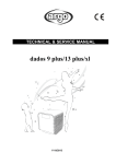
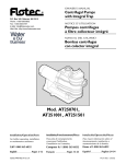
1.4 instructions on Names of Components of Frequency Converter
Button placement
for upper cover plate
Upper
cover plate
Power driving board
Keyboard operator
Control panel
Complete machine
mounting hole
Control panel terminal
Major loop terminal
Major loop cable inlet
Control cable inlet
Fig. 1-2 The Schematic Diagram of Names of
Components of Frequency Converter
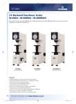
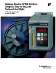
1.5 Overall Dimension of Frequency Converter
1.5.1 Overall Dimension
H
B
A
W
D
Fig. A
Fig. B
Fig. 1-3 The Schematic Diagram of Overall
Dimension of Frequency Co nverter
7
HV400 Series Vector Frequency Converter
Chapter 1 Overview
1.5.2Mechanical Parameter
Frequency Converter
Model
Installation Dimension
Overall Dimension
Mounting
Hole
Weight
(kg) ≈
118
Φ4
1.2
170
145
Φ4
1.5
125
170
145
Φ4
1.5
247
150
253
150
Φ5
3
225
375
250
400
195
Φ8
7.8
295
495
320
515
255
Φ8
22.5
230
565
375
580
265
Φ8
30
320
735
460
755
335
Φ8
60
─
─
490
1490
395
─
120
─
─
750
1670
400
─
200
A (mm)
B (mm)
W (mm)
H (mm)
D (mm)
115
160
125
170
110
160
125
110
160
135
HV400-R4G3-S2
HV400-R75G3-S2
HV400-1R5G3-S2
HV400-2R2G3-S2
HV400-R75G3
HV400-1R5G3
HV400-2R2G3
HV400-3R7G3/5R5P3
HV400-5R5G3/7R5P3
HV400-7R5G/110P
HV400-011G3/150P3
HV400-015G3/018P3
HV400-018G3/022P3
HV400-022G3/030P3
HV400-030G3/037P3
HV400-037G3/045P3
HV400-045G3/055P3
HV400-055G3/075P3
HV400-075G3/090P3
HV400-090G3/110P3
HV400-110G3/132P3
HV400-132G3/160P3
HV400-160G3/185P3
HV400-185G3/200P3
HV400-200G3/220P3
HV400-220G3/250P3
HV400-250G3/280P3
HV400-280G3/315P3
HV400-315G3/350P3
8
HV400 Series Vector Frequency Converter
Chapter 1 Overview
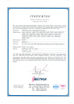
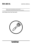
1.5.3 The Overall Dimension of Operation Panel
HB402
120mm
114mm
Side
87mm
Front
81mm
Back
19.5mm
Fig. 1.5.3-1The Figure of Keyboard Operator
Appearance and Installation Dimension
HB401
92mm
100mm
Side
70mm
Front
16.5mm
21.5mm
70mm
Back
Fig. 1.5.3-2 The Figure of Keyboard Operator
Appearance and Installation Dimension
9
HV400 Series Vector Frequency Converter
Chapter 2 Open-package Inspection
2. Open-package Inspection
Caution
●Don’t installing or running any damaged frequency converter or the one with fault part,
otherwise it will be at the risk of injury.
Although our products have passed strict inspection before delivery, please make sure to check
carefully after purchasing this product due to transportation or any unexpected case.
2.1 Inspection Items
Please confirm the following items when you get the product:
Item to Confirm
Confirming Method
Whether the type and the model are consistent with Please check the nameplate at the side
what you ordered.
of HV400.
Examining the overall appearance for
checking whether there is any damage
during transportation.
Whether some fastening parts become loosened, Checking with screwdriver when
such as screw and the like.
necessary.
Instruction Book, Warranty Card and other HV400 Operation Instruction and
accessories.
corresponding accessories.
Whether there is any damaged part.
Please contact with the supplier or the Sales Department of our company directly for any
exception.
10
HV400 Series Vector Frequency Converter
Chapter 3 Disassembly and Assembly
3. Disassembly and Assembly
Warning
●The equipment must be designed, installed, debugged and run by the trained and qualified
professionals; it must follow all provisions of “Warning” during the working, otherwise it may
cause serious personal injury or significant property loss.
●Only permanent fastening connection shall be allowed for input power line, and the equipment
must be grounded reliably.
●The following terminals may still carry dangerous voltage, even though the frequency converter is
under the power off position.
-power supply terminals R, S and T
- terminals U, V and W connected with motor
●It must wait for more than 10 minutes and confirm that the POWER light goes out and the
frequency converter discharges off, after switching off the power switch, and then the installation
may be allowed to start.
●The minimum section area of grounding conductor should be 10mm2 at least, or the maximum
value among the two items of the corresponding data in the Table below shall be selected as the
section area of grounding conductor:
Section Area S of Power Line Conductor mm 2
Section Area of Grounding Conductor
S≤16
S
16<S≤35
16
35<S
S/2
Caution
●Holding the base while uplifting the cabinet body instead of uplifting by grasping the panel for
moving the frequency converter, otherwise the main unit may fall and cause personal injury.
●The frequency converter should be installed on flame retardant materials, such as metal, away from
heat and inflammable object, so as to avoid a fire.
●When two or more frequency converters are installed in one cabinet body, a cooling fan should be
installed, and the air temperature should be controlled lower than 40℃, otherwise the overheating
may cause a fire or damage the device.
11
HV400 Series Vector Frequency Converter
Chapter 3 Disassembly and Assembly
3.1 Environmental Conditions for Frequency Converter to Operate
3.1.1 Temperature and Humidity
The operating ambient temperature shall be between -10℃ and +40℃, it must derate for using when the
temperature is higher than 40℃, and the temperature should not be more than 50℃. It should derate by 4%
per 1℃ rise, when the ambient temperature is higher than 40℃.
The relative air humidity should be less than or equal to 90%, there should be no condensation, the
frequency converter should also be avoided placing in the direct sunlight, and the temperature could be
represented in Fahrenheit.
3.1.2 Altitude
When the frequency converter is installed at the altitude under 1000m, it can run at its rated power. When
the altitude is higher than 1000m, the frequency converter power should be derated to the extent shown as
follows:
Fig. 3-1 The Altitude of Installation Site
3.1.3 Other Environmental Requirements
Please install at the place which would impossibly be vibrated and shocked violently, and the
maximum amplitude should be not more than 5.8m/S2 (0.6g).
Please install away from an electromagnetic radiant point.
Please install at the place where metal powder, dust, oil, water and the like could not immersed into the
frequency converter.
Please do not install in the environment with direct sunlight, oil mist, steam or saline matter.
12
Chapter 4 Wiring
HV400 Series Vector Frequency Converter
4. Wiring
Warning
●It must be operated by the eligible approved professional electronic personnel for ensuring the
safe operation of the frequency converter.
●It is forbidden to test the insulation of cable connected with the frequency converter by a high
voltage insulation test equipment.
●Even though the frequency converter is not under running state, the power input wire, the DC
circuit terminal and the electromotor terminal may still carry dangerous voltage, so it must
wait for more than 10 minutes and confirm that the POWER light goes out and the frequency
converter discharges off, after switching off the power switch, and then the installation may be
allowed to start.
●The ground terminal of the frequency converter must be grounded reliably with the ground
resistance less than 10Ω, and otherwise it may cause the risks of electric shock and fire.
●The three-phase power supply should not be connected with the output terminals (U, V and W)
of the frequency converter, and otherwise it may damage the frequency converter.
● Please confirm the correct connection of the power wire and the motor wire, with the power
wire connected with terminals R, S and T and the motor wire connected with the terminals of
U, V and W, before electrifying.
● It is forbidden to touch the frequency converter with wet hands, and otherwise it may cause the
electric shock.
Caution
●Please check whether the rated voltage of the frequency converter is consistent with the AC
supply voltage.
● The power wire and the motor wire must be permanently connected in a fastened way.
13
HV400 Series Vector Frequency Converter
Chapter 4 Wiring
4.1 Peripheral Equipment Connection Diagram
disconnecting switch
breaker or fuse
AC input electric reactor
contactor
input EMI filter
DC reactor
HV400
brake unit
braking resistor
output EMI filter
AC output electric reactor
3 phase asynchronous motor
Fig. 4-1 Peripheral Equipment Connection Diagram
4.2 Wiring Terminal Diagram
4.2.1 Three-phase description of Major loop Terminal Block
The three-phase major loop terminal block distribution diagrams are shown in figures 4-2 (a-d),
and the instruction on the functions of various terminals is shown as follows.
14
HV400 Series Vector Frequency Converter
Chapter 4 Wiring
a) The Major Loop Terminal Block Distribution Diagram of 3 phase 0.75kW-7.5KW Frequency
Converter (as shown in fig. 4-2b)
Fig.4-2a
b) The Major Loop Terminal Block Distribution Diagram of 3 phase 11kW-15kW
Frequency Converter (as shown in fig. 4-2b)
Fig. 4-2b
c) The Major Loop Terminal Block Distribution Diagram of 3 phase 18.5kW-110kW
Frequency Converter (as shown in fig. 4-2d)
Fig. 4-2c
d) The Major Loop Terminal Block Distribution Diagram of 3 phase 132kW-315kW Frequency
Converter (as shown in fig. 4-2d)
Fig. 4-2d
e) The Major Loop Terminal Block Distribution Diagram of 3 phase 132kW-315kW Frequency
Converter (as shown in fig. 4-2e)
15
HV400 Series Vector Frequency Converter
Chapter 4 Wiring
Terminal Function Description
Terminal Symbol
Function Description
DC side voltage positive
terminal
DC side voltage negative
terminal
DC Braking Resistor can be
connected between P and PB
DC reactor can be connected
between P1 and +
To be connected with pow er
grid three-phase AC pow er
supply
To be connected with
three-phase AC electromotor
P and +
﹣
PB
P1
R, S, T
U, V, W
ground terminal
4.2.2 Single-phase major loop terminal block distribution diagram is shown in figure 4-2e, and
the instruction on the functions of various terminals is shown as follows.
Fig. 4-2e
Terminal Function Description
Terminal Symbol
Function Description
DC side voltage positive
terminal
DC Braking Resistor can be
connected between P and B
To be connected with pow er
grid single-phase AC pow er
supp ly
To be connected with
single/three-phase AC
electrom otor
(+)
PB
L, N
U, V, W
ground terminal
4.2.3 Terminals of Control Loop:
485+
485-
+10V
GND
DI1
DI2
AI1
DI3
AI2
DI4
GND
DI5
AO1
DI6
AO2
DI7
COM
HDI
PW
HDO
+24V
COM
R1A
R1B
R2A
Fig. 4-3 Control Loop Wiring Terminal Diagram
16
R1C
R2B
R2C
HV400 Series Vector Frequency Converter
Chapter 4 Wiring
Fig. 4- 4 Standard Wiring Diagram
17
HV400 Series Vector Frequency Converter
Chapter 4 Wiring
4.3.1 Description of Control Panel Terminals
Term inal
Purpose and Description of Terminal
Nam e
on-off input terminal which forms optical coupling isolation input with +24V
and COM
DI1~DI7
input voltage range: 9~30V
input impedance: 3.3kΩ
HDI
high-speed pulse input or on-off input which forms optical coupling isolation
input with +24V and COM
pulse input frequency range: 0~50kHz
input voltage range: 9~30V,
input impedance: 1.1kΩ
+24V
+24V power supply provided for this equipment (current: 150mA)
COM
common terminal of +24V
AI1
analog input, voltage range: -10V~+10V
input impedance: 20kΩ
AI2
analog input, voltage (0~10V) /current (0~20mA), which can be selected via
J9
input impedance: 20kΩ (voltage input) /250Ω (current input)
+10V
+10V power supply provided for this machine (current: 10mA)
GN D
zero potential reference of +10V (Note: GND is isolated from COM)
HDO
high-speed pulse or open collector output terminal, the corresponding
common terminal of which is COM
output frequency range: 0~50 kHz
AO1, AO2
analog output terminal, wherein, AO1 can be selected voltage or current
output by jumper J8;
AO2 can be selected voltage or current output by jumper J7
output range: voltage (0~10V) /current (0~20mA)
RO1A, RO1B,
RO1C
RO1 relay output, RO1B common terminal, RO1A is normally closed, and
RO1C is normally open
contact capacity: AC250V/3A, DC30V/1A
RO2A, RO2B,
RO2C
RO2 relay output, RO2B common terminal, RO2A is normally closed, and
RO2C is normally open
contact capacity: AC250V/3A, DC30V/1A
485+, 485-
485 communication ports, positive and negative terminals for 485 differential
signal, please use twisted pair cable or shielded wire for standard 485
communication ports
18
HV400 Series Vector Frequency Converter
Chapter 4 Wiring
4.3.2 Description of Control Panel Jumper
Term inal
Purpose and Description of Terminal
Na me
The jumpers special for manufacturer, which should not be changed by the
J4,J5,J6
user, and otherwise is may cause the malfunction of the frequency converter.
Analog output (J8:AO1,J7:AO2) voltage (0-10V) /current (0-20mA) switching
J7,J8
J9
output. V: voltage, I: current
Analog input 2(AI2) voltage (0-10V) /current (0-20mA) switching. V:
voltage, I:current
4.4 Connection of Major Loop
4.4.1 Connection of Major Loop at the mains side
4.4.1.1 Breaker
A breaker with the power suitable for the frequency converter should be accessed between the
three-phase AC power supply and the power supply input terminals (R, S and T). The capacity
of the breaker should be 1.5 to 2 times of the rated current of the frequency converter. Please
refer to Capter 4.7 the List of Specifications for Breaker, Cable and Contactor and reactor for
details.
4.4.1.2 Electromagnetic Contactor
An electromagnetic contactor could be installed at the input side for controlling the on-off of the
major loop power supply, so as to switch off the input power of the frequency converter
effectively in case of the system failure and ensure the safety.
4.4.1.3 Input AC reactor
In order to prevent the large current from flowing into the input power loop and damaging the
components of rectification part at the moment of power grid spike pulse input, an AC reactor
should be accessed at the input side, which will also improves the power factor at the input side.
For protecting the frequency converter effectively, it suggest that the 380V-grade frequency
converter higher than 110KW should be added with input reactor, and the 220V-grade one
higher than 45KW should be also added with input reactor.
4.4.1.4 Noise Filter at the Input Side
During the using of frequency converter, other surrounding electronic equipments may be
interfered by the power wire, and this filter can reduce the interference towards the surrounding
19
HV400 Series Vector Frequency Converter
Chapter 4 Wiring
equipments. The specific wiring method is shown below:
power supply
Fig. 4-5 The Diagram of the Connection of Major Loop at the Mains Side
4.4.2 The Connection at the Major Loop Frequency Converter
4.4.2.1 DC reactor
DC reactor can improve the power factor and avoid damaging the rectifier bridge due to over
large current input of frequency converter resulted from accessing the large capacity transformer,
and it can also avoid damaging the rectifying circuit due to the harmonic wave resulted from
power grid voltage leap or phase control load.
4.4.2.2 Brake Unit and Braking Resistor
• HV400 series (380V-grade) frequency converter of 15kW and lower than 15kW should
be provided with brake unit internally, and it must be connected with braking resistor at the
terminals of P and PB for releasing the feedback energy at the moment of braking.
• The wiring for braking resistor should be at the length less than 5M.
• The temperature of the braking resistor may rise because of releasing energy, so it
should pay attention to safety protection and good ventilation when installing the braking
resistor.
•When external brake unit is required, the (+) and (-) terminals of the brake unit should be
corresponding with the (+) and (-) terminals of the frequency converter respectively, and
the braking resistor should be connected at the terminals P1 and PB of the brake unit.
• The wiring between the (+) and (-) terminals of the frequency converter and the (+) and
(-) terminals of the brake unit should be at the length less than 5M, and the wiring
between the terminals P1 and PB of the brake unit and the braking resistor should be at
the length less than 10m.
Note: the polarities of (+) and (-) should not be opposite; (+) and (-) terminals are not allowed to
be connected with the braking resistor directly, and otherwise it may damage the frequency
converter or cause the risk of a fire.
20
HV400 Series Vector Frequency Converter
Chapter 4 Wiring
4.4.3 Connection of Major Loop at the Motor Side
4.4.3.1 Output Reactor
When the distance between the frequency converter and the motor is more than 50m, because the
parasitic capacitance effect of long cable over the ground may cause the leakage current
overlarge, and the frequency converter may carry out overcurrent protection frequently, it must
add the output reactor for compensating, which also aims at avoiding the motor insulation
damage.
4.4.3.2 Noise Filter at Output Side
Adding the output noise filter can reduce the radio noise caused by the cable between
frequency converter and the motor and the leakage current of conducting wire.
21
Chapter 4 Wiring
HV400 Series Vector Frequency Converter
4.4.4 Connection of Common DC Bus
For the multi-motor drive applications such as paper manufacturing machine, chemical fiber and
the like, the scheme of common DC bus is generally adopted. At one point, a motor is under the
power-driven state, while the other motors are under the regenerative braking (power
generation) state. Here, the renewable energy could equalize on the DC bus automatically for
the motor under the power-driven state to use, which accordingly reduce the electric energy
absorbed by the entire system from the power grid and achieve the goal of saving energy.
The following it the schematic diagram of two synchronously working motors (reeling motor
and unreeling motor for example), wherein, one of them is always under the power-driven state,
and the other one is always under the regenerative braking state. The DC buses of two frequency
converters are in parallel connection, the renewable energy can be used by the power-driven
motor, so as to achieve the aim of saving energy.
Fig. 4-7 The Connection of Common DC Bus
Note: If selecting two frequency converters with common DC bus, it is preferred to select
those of the same type, and which should be electrified synchronously.
4.4.5 Connection of ground Wire (PE)
For ensuring the safety and preventing the accidents of electric shock and fire, the ground
terminal E of the frequency converter must be grounded properly with the ground resistance less
than 10Ω. The ground wire should be thick and short, which should be multiple copper cores
more than 3.5mm². When several frequency converters are grounded, common ground wire is
not recommended, so as to avoid the ground wire forming a circuit.
22
Chapter 4 Wiring
HV400 Series Vector Frequency Converter
4.5 Connection of Control Loop
4.5.1 Precautions
Please use multi-core shielded cable or twisted pair cable to connect the control terminals. When
using the shielded cable (near one end of the frequency converter), it should be connected with
the ground terminal
of the frequency converter. The controlling cable should be more
than 20cm away from the main circuit and high voltage lines (including power wire, motor wire,
relay, contactor cable and the like) during wiring, parallel wiring should be avoided, and
vertical wiring is recommended, so as to avoid the malfunction of the frequency converter
caused by external disturbance.
4.6 Installation Guide in accordance with EMC Requirement
4.6.1 General Knowledge about EMC
EMC is the abbreviation of electromagnetic compatibility and indicates the ability of running
normally in the electromagnetic environment and causing no unbearable electromagnetic
disturbance to any matter in such environment of equipment or system. EMC includes the
contents at two aspects: electromagnetic interference and electromagnetic anti-interference.
There are two types of electromagnetic interference according to the route of transmission:
conducted interference and radiated interference.
Conducted interference means the interference transmitted along the conductor, so all conductors,
such as conducting wire, transmission line, inductor, capacitor and the like, are the transmission
path for conducted interference.
Radiated interference means the interference transmitted in the form of electromagnetic wave,
the energy transmitted by which is inversely proportional to the square of distance.
Electromagnetic interference must meet three indispensable conditions also known as elements
at the same time: interference source, transmission path and sensitive receiver. EMC problem
should be mainly solved from these three aspects. For the users, the equipment as the
electromagnetic interference source or receiver could not be changed, so it will mainly focus on
the transmission path for solving the EMC problem.
Different electric equipments and electronic equipments have different EMC abilities due to the
different EMC standards or grades carried out by them.
4.6.2 The EMC Features of Frequency Converter
23
Frequency converter is the electromagnetic interference source as well as the electromagnetic
receiver in a power distribution system, just like other electric and electronic equipments. The
operating principle of the frequency converter determines that it will generate certain
Chapter 4 Wiring
HV400 Series Vector Frequency Converter
electromagnetic interference noise, and at the same time it must be designed to have certain
anti-electromagnetic interference ability for ensuring that the frequency converter is able to work
reliably in certain electromagnetic environment.
When the frequency converter system is
working, its EMC features are mainly reflected from the following aspects:
4.6.2.1 The input current is generally non-sinusoidal wave, and the current contains
abundant higher harmonics which may form the electromagnetic interference to the outside,
reduce the power factor of the power grid and increase the line loss.
4.6.2.2 The output voltage is high frequency PMW wave which may cause the temperature
rise of the motor and reduce the service life of the motor; it may increase leakage current and
cause the malfunction of the leakage protector, and at the same time it forms strong
electromagnetic interference to the outside and influences the reliability of other electric
equipments in the same system.
4.6.2.3 As the electromagnetic receiver, the over strong external interference will cause the
malfunction of the frequency converter and even damage it and will influence the normal use by
the users.
4.6.2.4 During the system wiring, the external interference of the frequency converter and
its own anti-interference performance are supplement each other, so the process of reducing the
external interference of the frequency converter is also the process of improving its own
anti-interference performance.
4.6.3 EMC Installation Guide
Combined with the EMC features of the frequency converter, this section will introduce the
EMC installation method from several aspects such as noise suppression, field wiring,
grounding, leakage current, the usage of power filter ant the like, in detail, for reference of field
installation, and it will achieve the good EMC effect only by fulfilling these five aspects.
4.6.3.1 Noise Suppression
All connecting wires for the control terminals of the frequency converter should be shielded wire,
the shielding layer of which will be grounded nearby the entrance of the frequency converter,
and the cable clamping piece is used for grounding to form 360 degree looping-in. It is forbidden
to twist the shielding layer as a braid shape and then in ground connection with the frequency
converter, which may reduce the shielding effect
24greatly and even lose the shielding effect.
The connecting wire (motor wire) for the frequency converter and the motor should be shielded
wire or independent wiring channel, one end of the shielding layer of the motor wire or the
metal enclosure shall be connected with the frequency converter nearby, and the other end shall
Chapter 4 Wiring
HV400 Series Vector Frequency Converter
be connected with the motor case. It the noise filter is installed at the same time, it will suppress
the electromagnetic noise greatly.
4.6.3.2 Field W iring
Electrical wiring: In different control systems, the power input wires should be electrified from
the power transformer independently, which should be usually five-core wire including three live
wires, one null line and one ground wire, and it is forbidden to share a wire as the null line and
the ground wire.
Equipment classification: Usually, there are different electrical equipments inside the same
control cabinet, such as frequency converter, filter, PLC, measuring instrument and the like,
which have different abilities of emitting electromagnetic noise and bearing noise, so it is
required to classify these equipments into strong noise equipment and noise-sensitive equipment.
The similar equipments should be installed in the same area, and different kinds of equipments
should be spaced more than 20cm.
Wiring inside control cabinet: Usually, there are signal line (weak current) and power line
(strong current) inside the control cabinet, and there are incoming line and outgoing line for the
frequency converter. The signal line may easily interfered by the power line, which accordingly
causes the malfunction of equipment. During wiring, the signal line and the power line should be
distributed in different area, it is forbidden to arrange these two kinds of lines in the manner of
parallel wiring or staggered wiring within a short distance (less than 20cm), and it must not
bundle them together. If the signal line must run across the power line, a 90-degree angle should
be kept between them. The incoming line and the outgoing line of the power lines should not be
staggered for wiring or bundled together, in particular in the occasion of installing a noise filter,
which may cause the electromagnetic noise forming coupling due to the distributed capacitance
of incoming line and outgoing line and accordingly result in that the noise filter is out of action.
4.6.3.3 Grounding
The frequency converter must be grounded safely and reliably when working. Grounding is not
only for the safety of equipments and personnel, but also the most efficient, simplest method for
solving EMC problem, with least cost, so it is preferred.
There are three ways of grounding: grounding by special grounding electrode, grounding by
common grounding electrode and grounding25by ground wire in series connection. Different
control systems should adopt the grounding by special grounding electrode, different equipments
within the same control system should adopt the grounding by common grounding electrode, and
different equipments within the same power supply line should adopt the grounding by ground
Chapter 4 Wiring
HV400 Series Vector Frequency Converter
wire in series connection.
4.6.3.4 Leakage current
Leakage current includes wire-to-wire leakage current and earth leakage current. Its magnitude is
determined by the size of distributed capacitance and the carrier frequency of the frequency
converter during system wiring. Earth leakage current means the leakage current flowing over
the common ground wire, which may not only flow into the frequency converter system but flow
into other equipments via the ground wire, and such leakage current may cause the malfunction
of leakage breaker, relay or other equipment. The wire-to-wire leakage current is the leakage
current flowing over the distributed capacitance between the cables at the input side and output
side of the frequency converter. The magnitude of the leakage current is related to the carrier
frequency of the frequency converter, the length of motor cable and the section area of cable,
and the higher carrier frequency of the frequency converter, the longer motor cable and the
larger section area of cable will result in larger leakage current.
Countermeasure:
The leakage current can be reduced effectively by reducing the carrier frequency. When the
motor wire is long (more than 50m), an AC reactor or sinusoidal wave filter should be installed
at the output side of the frequency converter, when the motor wire is longer, it should install one
reactor respectively at intervals.
4.6.3.5 Noise Filter
The noise filter can play a good role of electromagnetic decoupling, so it is recommended to
install it even if meeting the working condition.
Actually there are two types of noise filters:
1. The noise filter is added at the input terminal of the frequency converter for separating it
from other equipments.
2. The noise filter or the isolation transformer is added at the input terminal of other
equipment for separating it from the frequency converter.
4.6.4 Under the precondition of installing and wiring according to the contents of
Instruction Manual when installing the frequency converter and EMI filter, it may also
meet the requirements of the following specifications:
EN61000-6-4: The Detection of Electromagnetic
26
Interference of Product under Industrial
Environment
EN61800-3: Meet the EN61800-3 electromagnetic radiation standard (category-2 environment).
Chapter 4 Wiring
HV400 Series Vector Frequency Converter
It can meet the EN61000-6-3 electromagnetic radiation standard (residential environment) and
the EN61000-6-4 electromagnetic radiation standard (industrial environment) by equipping with
EMC filter.
4.7 Specifications for Breaker, Cable, Contactor and Reactor
4.7.1 Specifications for Breaker, Cable and Contactor
Type
Breaker
(A)
Incom
27 ing
Line/Outgoing Line
(Copper Cable) m m 2
Rated Working Current of
Contactor A (voltage 380 or220V)
HV400-2S/R75G3
16
2.5
HV400-2S/1R5G3
20
4
16
HV400-2S/2R2G3
32
6
20
HV400-2S/004G3
40
6
25
HV400-7R5G3/1R5P3
16
2.5
10
HV400-1R5G3/2R2P3
16
2.5
10
HV400-2R2G3/004P3
25
4
16
HV400-004G3/5R5P3
25
4
16
HV400-5R5G3/7R5P3
25
4
16
HV400-7R5G3/011P3
40
6
25
HV400-011G3/015P3
63
6
32
HV400-015G3/185P3
63
6
50
HV400-185G3/220P3
100
10
63
HV400-220G3/300P3
100
16
80
HV400-300G3/370P3
125
25
95
HV400-370G3/450P3
160
25
120
HV400-450G3/550P3
200
35
135
HV400-550G3/750P3
200
35
170
HV400-750G3/900P3
250
70
230
HV400-900G3/110P3
315
70
280
HV400-110G3/132P3
400
95
315
HV400-132G3/160P3
400
150
380
HV400-160G3/185P3
630
185
450
HV400-185G3/200P3
630
185
500
HV400-200G3/220P3
630
240
580
HV400-220G3/250P3
800
150x2
630
HV400-250G3/280P3
800
150x2
700
HV400-280G3/315P3
1000
185x2
780
HV400 Series Vector Frequency Converter
28
10
Chapter 4 Wiring
Chapter 4 Wiring
HV400 Series Vector Frequency Converter
Type
Breaker
(A)
Incom ing
Line/Outgoing Line
(Copper Cable) mm 2
Rated Working Current of
Contactor A (voltage 380 or220V)
HV400-315G3/350P3
1200
240x2
900
HV400-350G3/400P3
1280
240x2
960
HV400-400G3/500P3
1380
185x3
1035
HV400-500G3/560P3
1720
185x3
1290
HV400-560G3/630P3
1900
185x3
1425
HV400-630G3
2200
240x3
1650
4.7.2 Specifications for Input/output AC Reactor and DC Reactor
Input AC Reactor
Output AC Reactor
DC Reactor
Frequency Converter Capacity
Current Inductance Current Inductance Current Inductance
KW
(A)
(mH)
(A)
(uH)
(A)
(mH)
HV400-037G3/045P3
75
0.24
80
90
100
0.85
HV400-045G3/055P3
91
0.23
90
80
120
0.70
HV400-055G3/075P3
112
0.17
150
60
146
0.58
HV400-075G3/090P3
150
0.16
150
40
200
0.47
HV400-090G3/110P3
180
0.12
250
35
238
0.35
HV400-110G3/132P3
220
0.10
250
30
291
0.29
HV400-132G3/160P3
265
0.09
290
20
326
0.24
HV400-160G3/185P3
300
0.08
330
16
395
0.22
HV400-185G3/200P3
360
0.07
400
13
494
0.18
HV400-200G3/220P3
360
0.06
490
11
494
0.14
HV400-220G3/250P3
400
0.05
490
9
557
0.13
HV400-250G3/280P3
530
0.03
530
8
650
0.10
HV400-280G3/315P3
560
0.02
600
5.5
700
0.08
800
0.06
460*2
0.12
460*2
0.12
650*2
0.11
650*2
0.11
660*2
0.09
HV400-315G3/350P3
660
0.02
660
HV400-350G3/400P3
400*2
0.04
400*2
HV400-400G3/500P3
490*2
0.03
490*2
HV400-500G3/560P3
530*2
0.03
530*2
HV400-560G3/630P3
HV400-630G3
600*2
660*2
0.02
0.02
29
600*3
660*2
2
5
4
3
3
3
HV400 Series Vector Frequency Converter
Chapter 5 Operation
5. Operation
5.1 instructions on Operation Panel
5.1.1 The Schematic Diagram of Panel
Function
Indicator Light
Second Line of Digital
Display
Run Key
Potentiometer
Regulation
Stop/Reset Key
Inching/Reversing Key
Increasing/Decreasing Key
Menu Key
Shift Key
Enter Key
Fig. 5-1 The Schematic Diagram of Operation Panel
5.1.2 Description of Key Functions
Key
Symbol
Name
Programming
Key
Enter Key
UP Increa sing
Key
DOWN
decreasing Key
Shift Key
Run Key
Stop/Reset Key
Quick/Jog Key
Function Description
Entering into or exiting from first menu and deleting
shortcut parameters
Entering into the menu screen gradually and
confirming the setup parameters
Increasing data o function code progressively
Decreasing data o function code progressively
Being capable of cyclical selection of the display
parameter under the stop display interface and run
display interface; being capable of selecting the
modified bit of parameter for modifying the parameter
Being used for running operation under the mode of
keyboard operation
Under the running state, it can stop running operation
by pressing this key, which is controlled by function
code P7.04; under the failure warning state, it can reset
the failure by this key, which is not controlled by
Function Code P7.04.
The function of this key is determined by function code
P7.03.
0: Switching display state shift key
1: Inching operation
2:Switching between forwarding and reversing as a
forwarding/reversing switching key
3: Clearing UP/DOWN setting and clearing the
frequency value set by UP/DOWN
4: Fast debug mode (debugging according to the
parameters other than factory defaults)
30
HV400 Series Vector Frequency Converter
Chapter 5 Operation
Key
Symbol
Name
+
Combination
The frequency converter will stop freely when RUN key and
STOP key are pressed at the same time
Keypad
potentionmeter
The output frequency of HV400 can be changed by the Keypad
potentionmeter, It’s determined by Function Code P0.07.
Function Description
5.1.3 Description of Indicator Lights
1) Description of Function Indicator Lights:
Description of Indicator Light
Name of Indicator Light
Running state indicator light:
Light out means that the frequency converter is in the state of
RUN
shutdown; Light flicker means that the frequency converter is in
the state of parameter self-learning; Light on means that the
frequency converter is in the running state;
Forwarding/reversing indicator light:
F/R
Light out means forwarding state; Light on means reversing state.
Control mode indicator light:
TRIP
Light out means keyboard control state; Light flicker means
terminal control state; Light on means remote communication
control state.
2) Description of Unit Indicator Lights
Name of Indicator Light
Description of Indicator Light
Hz
frequency unit
A
current unit
V
voltage unit
RPM
rotation rate unit
%
percentage
3) Digital Display Area:
5 bits of LED display can display various supervision data and alarm codes, such as set frequency, output
frequency and the like.
31
HV400 Series Vector Frequency Converter
Chapter 5 Operation
5.2 Operation Procedure
5.2.1 Parameter Setting
Three menus are:
1. Function code group number (first menu);
2. Function code mark number (second menu);
3. Function code set value (third menu).
Explanation: When operating under third menu, it can return to second menu by pressing PRG or DATA,
the difference of which lies in that it can store the setup parameter into the control panel, then return to the
second menu and remove to next function code automatically by pressing DATA; while it can return to the
second menu directly without storing the parameter and keep resting on the current function code by
pressing PRG.
Example: changing the setting of function code P1.01 from 00.00Hz to 01.05Hz, for example.
Stop/Running State
50.00
PRG
00.00
PRG
P0.
01.05
DATA
P1.
PRG
DATA
P1.02
DATA
P1.00
PRG
P1.
PRG
P1.01
PRG
(存入参数)
PRG
50.00
DATA
00.00
Fig. 5-2 Operation Flow Chart of Third Menu
32
HV400 Series Vector Frequency Converter
Chapter 5 Operation
Under the state of the third menu, if there is no flicker bit in the parameter, it means that it is impossible to
modify such function code, and the possible causes include:
1) Such function code is non-modifiable parameter, such as actual detecting parameter, operation
record parameter and the like;
2) Such function code can not be modified under the running state and could be modified only after
shutdown.
5.2.2 Fault Reset
The frequency converter will prompt relevant fault information after the occurrence of fault. The user can
carry out fault reset by the STOP key on the keyboard or the terminal function (Group P5), and the
frequency converter will become the standby state after fault reset. If the frequency converter is in the fault
state, and the user does not process it by fault reset, the frequency converter will become the operation
protection state, and the frequency converter will be unable to run.
5.2.3 Motor Parameter Self-learning
If it selects the run mode of vector control with PG, the nameplate parameter of motor must be input exactly
before the operation of the frequency converter, the frequency converter will match standard motor
parameter according such nameplate parameter; the vector control mode relies on the motor parameter
strongly, so it must obtain the exact parameter of controlled motor for achieving good control performance.
The operation steps for motor parameter self-learning are as follows:
Firstly, the keyboard command channel shall be selected as the operation command channel selection
(P0.01=0).
Then, please input the following contents according to the actual motor parameter:
P2.01: rated power of motor;
P2.02: rated frequency of motor;
P2.03: rated revolution of motor;
P2.04: rated voltage of motor;
P2.05: rated current of motor.
Note: the motor should be detached from load, and otherwise the motor parameters obtained by
self-learning would be incorrect. P0.16 shall be set as 1, and please refer to the description of function
code P0.16 for the detailed motor parameter self-learning process. Then the frequency converter will
calculate the following parameters automatically after the user press the RUN key on the keyboard:
P2.06: motor stator resistance;
P2.07: motor rotor resistance;
P2.08: the inductances of motor stator and rotor;
33
HV400 Series Vector Frequency Converter
Chapter 5 Operation
P2.09: the mutual inductance of motor stator and rotor;
P2.10: motor no-load current; finishing motor parameter self-learning.
During the process of self-learning, the keyboard will display TUN-0 and TUN-1, when the keyboard
displays -END-, the process of motor parameter self-learning will be finished.
5.2.4 Password Setting:
HV400 series frequency converter provides the user password protection function. When P7.00 is set as
non-zero, which will be the user password. After exiting from function code editing state, the password
protection will become effective. When PRG key is pressed for entering into the function code editing state,
it will show “0.0.0.0.0”, the operator must input the correct password, and otherwise he could not enter.
It can cancel the password protection function by setting P7.00 as 00000. The user password takes no
protection function on the parameters in the shortcut menu.
5.3 Running State
5.3.1 Initialization for Electrifying
As the electrifying process of the frequency converter, the system carries out the initialization firstly, and
LED shows “8.8.8.8.8”. After the initialization finished, the frequency converter will be in the standby state,
and LED will show “POFF”, when the voltage does not reach certain value.
5.3.2 Standby
Under the shutdown or running state, various state parameters will be displayed. It can select whether these
parameters are displayed or not by the function codes P7.06 and P7.07 (running parameters) and P7.08
(shutdown parameter) according to the binary bit, and please refer to the description of function codes P7.06,
P7.07 and P7.08 for the definition of each bit.
Under the shutdown state, there are eleven shutdown state parameters to be selected whether being
displayed or not, including set frequency, bus voltage, input terminal state, output terminal state, PID set
value, PID feedback value, analog AI1, analog AI2, high-speed pulse HDI frequency, current stages of
PLC and multistage velocity and torque set value. The function code P7.08 will select whether displaying
or not according to bit (translated into binary bit), the selected parameters will be switched to be displayed
orderly by pressing
>>/SHIFT
key, and the selected parameters will be switched to be displayed orderly
towards the left by pressing the
QUICK/JOG
key (P7.03=0).
5.3.3 Operation
Under the running state, there are twenty two state parameters to be selected whether being displayed or not,
34
HV400 Series Vector Frequency Converter
Chapter 5 Operation
including operation frequency, set frequency, bus voltage, output voltage, output current, operating speed,
linear velocity, output power, output torque, PID given value, PID feedback value, input terminal state,
output terminal state, torque set value, current stage of PLC or multistage velocity, analog AI1, analog AI2,
high-speed pulse HDI frequency, overload percentage of motor and overload percentage of frequency
converter. The function codes P7.06 and P7.07 will select whether displaying or not according to bit
(translated into binary bit), the selected parameters will be switched to be displayed orderly towards the
right by pressing
>>/SHIFT
the left by pressing the
key, and the selected parameters will be switched to be displayed orderly towards
QUICK/JOG
key (P7.03=0).
5.3.4 Fault
HV400 series frequency converter provides various kinds of fault information. Please refer to HV400 Series
Frequency Converter Faults and Countermeasures for details.
5.4 Quick Menu
The quick menu provides the method for viewing and modifying function parameters faster. After P7.03 is
set as 4, the frequency converter will search out the current parameters which are different from the factory
defaults automatically after the
QUICK/JOG
key is pressed, and these parameters will be stored in the fast
debug menu according to the sequence of function codes for the user to view and set. The length of the quick
menu buffer zone is 32, the recorded parameters will be searched according to the sequence of function
codes. If the recorded parameters are more than 32, the exceeding parameters will not be displayed. It will
enter into the fast debug mode by pressing
QUICK/JOG .
If it shows “NULLP” after pressing
QUICK/JOG ,
it
means that all current parameters are identical with the factory defaults. After entering into the fast debug
menu, it will exit from the third menu (function code set value) or exit from the mode of quick menu by
pressing QUICK/JOG key.
35
Chapter 5 Operation
HV400 Series Vector Frequency Converter
6. Function Description in
Detail
must set the motor template parameters
Group P0 Basic Function Group
correctly
Function
Code
Name
Setting Range
parameter self-learning before operation,
P0.00
election of
speed control
mode
0~2【0】
of motor and the coder parameters
so
as
and
to
finishing
get
parameters.
It
the
the
motor
accurate
may
bring
motor
the
high
performance of the vector control into
It is for selecting the speed control mode of
play only on the basis of obtaining
the frequency converter.
accurate motor parameters.
0: V/F Control
The vector control performance can be
V/F control is adapted for the speed
optimized by adjusting the vector control
regulation
parameters (Group P3).
occasion
with
not
so
high
requirement on control accuracy and could
be also used for the occasion of dragging
several motors by one frequency converter.
1: Vector Control without PG
Function
Co de
Name
Setting Range
P0.01
operation
comm and
channel
0~2【0】
It is namely open-loop vector, which is
adapted for the debugging occasion or the
It is for selecting the control command
frequency control occasion with not so high
channel for the frequency converter. The
requirement on accuracy. The mode of
frequency
vector control without PG is adapted for the
include
high performance general occasion without
reversing, inching, fault reset and the like.
pulse coder and the occasion with the
0: Keyboard Command Channel
requirement of large low-frequency torque
The RUN and STOP keys on the keyboard
and the high requirement on speed control
panel carry out the command control. If the
accuracy. One frequency converter could
multifunctional key
drive only one motor, such as the loads of
FWD/REV switching function (P7.03 as 2),
machine tool, centrifugal machine, drawing
it can change the operation direction by this
mill, injection molding machine and the like.
key;
2: Torque Control (Vector Control without
frequency converter can shut down freely
PG)
by pressing the RUN and STOP keys
It is pen-loop vector, which is adapted for
synchronously.
the occasion with not so high requirement on
1: Terminal Command Channel
accuracy.
The multifunctional Digital input terminal
Note:
carries out the operation command control,
If selecting the mode of vector control, it
such
converter
starting,
under
the
control
shutdown,
QUICK/JOG
running
commands
forwarding,
is set as
state,
as forwarding, reversing,
inching, reverse inching and the like.
36
the
forward
Chapter 5 Operation
HV400 Series Vector Frequency Converter
2: Communication Command Channel
3: being valid while operating. The “
The operation command shall be controlled
and “
by the upper computer by means of
UP/DOWN function will be valid when is
communication.
Function
Name
Code
keyboard and
term inal
P0.02
U P/DO W N
setting
operates, and the setting will be cleared
setting
(increasing
” on the keyboard and the terminal
Note: When the user recover the default
0~3【0】
values for the function parameters of the
frequency converter, the setting of the
“∧”
keyboard
and
the
frequency
progressively/decreasing
the
frequency setting progressively) function,
the authority of which is highest, and they
terminal
UP/DOWN
It is used for setting the maximum output
can be combined with any other frequency
frequency of the frequency converter. It is
setting channel. It is mainly used for the fine
the basis for frequency setting as well as the
adjustment of the output frequency of the
basis of the speed of acceleration and
frequency converter during the process of
deceleration,
debugging the control system.
so
the
users should pay
attention to it.
Function
Name
Co de
0: valid, and the frequency converter will
store after power loss. The
and
function will be cleared automatically.
Function
Name
Setting Range
Co de
maxim um
10.00~600.00Hz
P0.03
output
【50.00Hz】
frequency
on the keyboard and the terminal
UP/DOWN
”
automatically when it shuts down.
Setting Range
The frequency shall be set by
“∨”
∨
∧
frequency
command can be set, and the frequency
P0.04
converter will store such set frequency value
upper limit of
operation
frequency
Setting Range
P0.05~P0.03
【50.00Hz】
after power down and will automatically
It is the upper limit of the output frequency
combine it with the current set frequency
of the frequency converter. This value
after being electrified next time.
should be less than or equal to the maximum
1: valid, and the frequency converter will
output frequency.
Function
Name
Co de
not store after power loss. The frequency
command can be set, and this set frequency
will not be stored after the frequency
P0.05
converter powers down.
2: invalid. The “
keyboard and
∧
the
” and “
∨
” on the
terminal UP/DOWN
lower limit of
operation
frequency
Setting Range
0.00~P0.04
【0.00Hz】
It is the lower limit of the output frequency
function are invalid, and the setting will be
of the frequency converter.
cleared automatically.
It can be selected by the function code P1.12,
when the set frequency is lower than the
37
Chapter 5 Operation
HV400 Series Vector Frequency Converter
action at the lower limiting frequency, it will
Note: When analog AI2 selects the input
operate, shut down or sleep according to the
of 0~20mA, the voltage corresponding to
lower limiting frequency. Wherein, the
20mA is 5V.
maximum output frequency will be ≥ upper
100.0% of analog input is corresponding to
limiting frequency and ≥ lower limiting
the maximum frequency (Function Code
frequency.
Function
Co de
P0.03), and -100.0% is corresponding to the
P0.06
Name
setting
frequency
by keyboard
Setting
Range
reversed
maximum
frequency
(Function
Code P0.03).
0.00~P0.03
【50.00Hz】
4: High-speed Pulse Setting (HDI)
The frequency is given by the input of
When the frequency A command selection is
terminal high-speed pulse. The standard
“keyboard setting”, this function code value
configuration of HV400 series frequency
will set the initial value for the frequency
converter provides 1 path of high-speed
number of the frequency converter.
Function
Setting
Name
Co de
Range
frequency A
0~8【0】
P0.07
comm and
pulse input (HDI).
Pulsed voltage: 15~30V; pulsed frequency:
0.0~50.0 kHz.
selection
100.0% of the pulse input setting is
It is for selecting frequency A command
corresponding to the maximum frequency,
input channel for the frequency converter.
and -100.0% of the pulse input setting is
There are totally 8 main given frequency
corresponding to the reversed maximum
channels:
frequency.
0: keyboard setting
Note: The pulse setting could only be input
It can achieve the aim of setting frequency
from the multifunctional terminal HDI, HDI
via keyboard by modifying the value of
is set as high-speed pulse input (P5.00=0),
function code P0.06 “setting frequency by
and HDI function is selected as “setting
keyboard”.
input”.
1:Keypadpotentiometer Setting
5: Simple PLC Program Setting
2: Analog AI1 Setting
3: Analog AI2 Setting
When this frequency setting method is
selected, the frequency converter will run in
It means that the frequency shall be set by
the form of simple PLC program. It is
the analog input terminal. The standard
required to set the parameters of group PA
configuration of HV400 series frequency
“simple PLC and multistage velocity control
converter provides 2 paths of analog input
group” for confirming the given frequency,
terminal, wherein, AI1 is the input of
operation direction and even the time for
-10V~10Vvoltage; and AI2 is the input
of 0~10V/0(4)~20mA. The current /voltage
input can be switched by the jumper J9.
acceleration/deceleration
for
each
stage.
Please refer to the introduction on the
38
Chapter 5 Operation
HV400 Series Vector Frequency Converter
selection
function of group PA for details.
6: Multistage Velocity Running Setting
0: Analog AI1 Setting
When this frequency setting method is
1: Analog AI2 Setting
selected, the frequency converter will run in
2: High-speed Pulse (HDI) Setting
the form of multistage velocity. It is required
When frequency B command is used as
to set the parameters of groups P5 and PA
independent
for confirming the given frequency. If P0.07
(given channel B is selected as the frequency
has not been set as multistage velocity
setting source), its usage is the same as that
setting, the multistage velocity setting will
of frequency command A. Please refer to
have priority, but its priority level will be
P0.07 description concretely.
Function
Name
Setting Range
Co de
selection of
reference
0~1【0】
object for
P0.09
still lower than inching running. When
multistage velocity setting has priority, only
1~15 stages could be set. If P0.07 is set as
multistage velocity setting, it may set 0~15
frequency
setting
channel
frequency B
comm and
stages.
7: PID Control Setting
0: maximum output frequency, 100% of
When this parameter is selected, the running
frequency B setting is corresponding to the
mode of the frequency converter will be
maximum output frequency.
process PID control. Then, it is required to
1:
set group P9 “PID control group”. The
frequency B setting is corresponding to the
operation
frequency
maximum output frequency. This setting
converter shall be the frequency value after
could be selected for regulating on the basis
PID regulation. Wherein, for the meanings
of frequency A command.
of
Note: When 0~20mA input is selected as
frequency
PID given
of
the
source, given
amount,
frequency
A
command,
100%
of
feedback source and the like, please refer to
analog AI2, the voltage corresponding to
the introduction on the “PID function” of
20mA shall be 5A. The function code
group P9.
P0.09 will be applied only when the
8: Remote Communication Setting
frequency
upper
computer
by
means
of
communication. Please refer to chapter 9 the
Frequency
Converter
Communication Protocol.
Function
Name
Code
frequency B
P0.08
command
command
is
used
as
superposition setting.
Function
Name
Setting Range
Co de
combination
0~3【0】
P0.10
mode of setting
sources
The frequency command shall be given by
the
B
Modbus
0: A, the current frequency setting channel is
Setting Range
frequency A command.
0~2【0】
1: B, the current frequency setting channel is
39
Chapter 5 Operation
HV400 Series Vector Frequency Converter
frequency B command.
maximum frequency, the actual time for
2: A+B, the current frequency setting
acceleration/deceleration is consistent with
channel
the set time for acceleration/deceleration.
is
frequency
command
A
+
frequency B command.
When the set frequency is less than the
3: Max (A, B) : Indicating that frequency A
maximum frequency, the actual time for
command will be the set frequency, if
acceleration/deceleration is less than the set
frequency
time for acceleration/deceleration.
frequency
A
B
command
is
command.
larger
than
Otherwise,
Actual time for acceleration/deceleration=set
frequency B command will be the set
time
frequency.
frequency/maximum frequency)
Note: the combination mode of (0, 1 and 2)
HV400 series frequency converter has 4 sets
can be switched by terminal function (group
of time for acceleration or deceleration.
P5).
Function
Code
Group one: P0.11, P0.12;
Name
P0.12
acceleration/deceleration×
(set
Group two: P8.00, P8.01;
Setting Range
Group three: P8.02, P8.03;
0.1~3600 .0s
time for
【determined by
acceleration 0
m odel】
0.1~3600 .0s
time for
【determined by
deceleration 0
model】
P0.11
for
Group four: P8.04, P8.05.
The time for acceleration/deceleration can
be selected by the combination of the
selection
terminal
of
time
Time for acceleration means the time for the
acceleration/deceleration
frequency converter to accelerate from 0Hz
multifunctional digital input terminal.
Function
Name
Setting Range
Co de
selection of
0~2【0】
P0.13
operation
to the maximum output frequency (P0.03).
Time for deceleration means the time for the
frequency converter to decelerate from the
in
for
the
direction
maximum output frequency (P0.03) to 0Hz.
f MAX
0: running towards default direction. After
output frequency
being electrified, the frequency converter
will run towards the actual direction.
f S ET
1: running towards opposite direction. It is
used for changing the motor steering, and its
function is to change the direction of
rotation of motor by adjusting any two
Actual time for
acceleration
motor wires.
Note:
After
the
initialization
of
Fig. 6-1 The Schematic Diagram of Time for
parameters, the running direction of the
Acceleration/dece leration
motor will restore to the original state.
When the set frequency is equal to the
40
Chapter 5 Operation
HV400 Series Vector Frequency Converter
Please use with caution for the occasion
frequency converter, (it is required to use the
that it is forbidden to changing the motor
frequency converter by derating under the
steering after the system is debugged.
high carrier frequency), increased leakage
2: forbidding reverse running. The reverse
current of the frequency converter, and the
running of the
increased electromagnetic interference to the
frequency converter is
forbidden, and it shall be applied to the
outside.
specific occasion of forbidding reverse
The case of low carrier frequency will be
running.
Function
Code
contrary to the above situation, the over low
P0.14
Name
Setting Range
carrier frequency will cause the instability of
carrier
frequency
setting
1.0~15.0kHz
【determined by
running at low frequency, the reduced torque
and even the oscillation phenomenon.
model】
The
carrier
frequency
has
been
set
reasonably, before the frequency converter
leaves factory. Generally, the user doesn’t
have to modify this parameter.
If the user uses at the carrier frequency over
the default value, it is required to use by
derating, and 20% should be derated for
Fig. 6-2 The Diagram of the Influence of
Carrier Frequency on Environment
increasing every 1k carrier frequency.
Function
Name
Setting Range
Co de
AVR function
0~2【1】
P0.15
selection
The Table of Relation between Model and
Carrier Frequency
Maxim Minim
carrier
um
um
Factory
frequency carrier carrier
default
frequen frequen
(kHz)
model
cy
cy
(kHz) (kHz)
0.4~11kW
15
1.0
5
15~55kW
8
1.0
4
75~630kW
6
1.0
2
AVR function is the function of regulating
output voltage automatically. When AVR
function is invalid, the output voltage will
change along with the input voltage (or the
voltage of DC bus); when AVR function is
valid, the output voltage will not change
along with the input voltage (or the voltage
The advantages of high carrier frequency:
ideal
current
wave
form,
less
of DC bus), and the output voltage will be
current
essentially constant within the range of
harmonic wave, low noise of motor;
output capability. If the time for deceleration
The disadvantages of high carrier frequency:
Increased
switching
loss,
is too long and could not meet the field
increased
demand,
temperature rise of the frequency converter,
the
AVR
function
could
be
canceled, which is conductive to shortening
influencing the output capability of the
the time for deceleration.
41
Chapter 5 Operation
HV400 Series Vector Frequency Converter
Function
Code
Name
Setting Range
P0.16
m otor
param eter
self-learning
0~2【0】
operation of parameter self-learning.
Note: The
parameter self-learning could only be
controlled by the keyboard; this function
0: no operation.
code will restore to 0 after the parameter
1: comprehensive parameter self-learning
self-learning is finished.
Before the motor parameter self-learning,
2: Static Parameter Self-learning
the motor nameplate parameters (P2.01 -
It is unnecessary to detach the motor form
P2.05) must be input correctly, the motor
the
must be detached from load to leave it in
motor
after self-learning. The mutual inductance
the inertness of motor, and otherwise there
and no-load current of the motor will be
would be the faults of over current and over
unable to be measured, and the user can
motor
input corresponding values as a matter of
parameter self-learning.
starting motor parameter self-learning, then
experience.
Function
Co de
LED will display “-TUN-” and flicker,
P0.17
Setting P0.16 as 1 and then press DATA for
RUN
parameter
Before
and the leakage inductance of the motor
P0.12) should be set properly according to
pressing
static
resistance and rotor resistance of the motor
the time for acceleration/deceleration (P0.11,
of
motor.
correctly, and it should detect the stator
Before the motor parameter self-learning,
process
the
of
parameters (P2.01 - P2.05) must be input
would be incorrect.
the
during
parameter self-learning, the motor nameplate
motor parameters obtained by self-learning
during
load
self-learning
still or unloaded state, and otherwise the
voltage
starting and stopping of
for
carrying
out
the
Name
Setting Range
functional
parameter reset
0~2【0】
0: no operation
parameter self-learning, and it will display
1: the frequency converter will recover all
“TUN-0”. After it displays “TUN-1”, the
parameters to default values
motor
will
“RUN/TUNE”
run,
while
flickers.
It
the
will
light
2: the frequency converter will clear the
display
recent fault record
“-END-” at the end of the parameter
This function code will recover to 0
self-learning, and finally it will display
automatically after the operation of selected
returning to the interface of down state.
function finished.
When “-TUN-” is flickering, you can PRG
press for exiting from the state of parameter
P1Group Start-stop Group
self-learning.
It can press STOP during the process of
Function
Co de
Name
Setting Range
parameter self-learning for stopping the
P1.00
operation mode
of starting
0~2【0】
42
Chapter 5 Operation
HV400 Series Vector Frequency Converter
0: starting directly. It means starting with the
frequency will act during the process of
starting frequency.
forwarding/reversing switching.
Function
Name
Setting Range
Co de
braking current 0.0~150.0%
P1.03
before starting
【0.0%】
braking time 0.0~50.0s【0.0s 】
P1.04
before starting
1:
DC braking before starting. It shall
begin with DC braking (pay attention to set
the parameters P1.03, P1.04), and then it
shall run by starting the motor at the start
frequency. It is adapted for the occasion that
P1.03 is the added value of DC current at the
the small inertia load may reverse at the time
time of DC braking before starting is the
of starting.
percentage of the rated current of the
2: speed tracking before starting. The
frequency converter.
frequency converter will calculate the speed
P1.04 is the duration of DC current. If DC
and direction of the motor firstly and then
braking time is set as 0, DC braking will be
starting running at the current speed, so as to
invalid.
realize the smooth shock-free starting of the
If the DC braking current is larger, the
motor. It is adapted for restarting after
braking force will be larger.
Function
Name
Setting Range
Co de
selection of
0~1【0】
P1.05
accelera ting/de
celerating mode
momentary interruption of great inertia load.
This function is limited to the models higher
than 11KW.
Function
Name
Setting Range
Code
start frequ ency
0.00~10.00
P1.01
for direct
【1.50Hz】
starting
retention time
P1.02
of starting 0.0~50.0s【0.0s 】
frequency
It is used
for setting
It is used for selecting the changing mode of
frequency during the processes of starting
and running.
0: linear type
The output frequency will increase or
proper starting
decrease progressively in a linear way.
frequency and can increase the torque at the
will start running at the starting frequency
1: retaining
Function
Co de
(P1.01) over the retention time of starting
P1.06
time of starting. The frequency converter
frequency (P1.02) and then will accelerate to
Name
Setting Range
selection of
shutdown mode
0~1【0】
0: ramp shutdown
the target frequency for the set time for
After the shutdown command becomes
acceleration. If the target frequency is less
effective,
than the starting frequency, the frequency
the
frequency
converter
will
reduce the output frequency according to the
converter will be in the standby state. The
mode of decelerating and the defined time
value of starting frequency is not limited by
for deceleration and will shut down when
the lower limiting frequency. The starting
the frequency is reduced to 0.
43
Chapter 5 Operation
HV400 Series Vector Frequency Converter
1: free shutdown
of DC braking quantity
After the shutdown command becomes
输 出 频 率 frequency
Output
effective, the frequency converter will stop
outputting immediately. The load will shut
Time
时 间t
down freely according to the mechanical
输 出 电 压 voltage
Output
Function
Code
Name
Setting Range
DC braking at the time停
of
shutdown
机
时
直
流
制
动
起 动 time
时 直 流at制the
动 时time
间 of starting
制
动
等
待
时
间
DC braking
Time
t
start frequ ency
时
间
Latency
time
for
braking
制
动
等
待
时
间
0.00~P0.03
for shu tdown
【0.00Hz】
Fig. 6-3 The Schematic Diagram of DC
braking
Braking
latency time for
Function
P1.08
shutdown 0.0~50.0s【0.0s 】
Name
Setting Range
Co de
braking
dead-time for
0.0~3600.0s
DC braking
0.0~150.0%
P1.11
forwarding and
P1.09
current for
【0.0s】
【0.0%】
reversing
shutdown
It is used for setting the transient time for the
DC braking
0.0~50.0s【0.0s 】
time for
P1.10
part of outputting zero frequency during the
shutdown
transient process of forwarding and
Start frequency for shutdown braking:
reversing, which is shown as follows:
during the process of decelerating for
P1.07
shutdown, it will start shutdown DC braking
when reaches this frequency.
If the start
Dead-time
Forwarding
frequency for shutdown braking is 0, DC
braking will be invalid, and the frequency
Time
converter will shut down according to the set
Reversing
time for deceleration.
Fig. 6-4 The Schematic Diagram of
Dead-time for Forwarding and Reversing
Function
Name
Setting Range
Co de
action at the
opera tion
frequ ency
0~2【0】
P1.12
lower than the
lower limit of
frequ ency
Latency time for shutdown braking: before
starting
shutdown
DC
braking,
the
frequency converter will block the output
and will start DC braking after such latency
time. It is used for preventing the fault of
over current caused by starting DC braking
at high speed.
DC braking current for shutdown: indicating
This function code is used for confirming
the added quantity of DC braking. If this
the running state of the frequency converter
value is higher, the braking torque will be
when the set frequency is lower than the
larger.
lower limit of frequency.
DC braking time for shutdown: the duration
44
Chapter 5 Operation
HV400 Series Vector Frequency Converter
0: running at the lower limit of frequency.
after being electrified again if it was the
1: shutdown.
running start before power down (it must
set
ensure that the operating terminal is still in
frequency is lower than the lower limit of
the closed state, when it is controlled by the
frequency, the frequency converter will shut
terminal), and it was the shutdown state
down freely; and when the set frequency is
before power down, the frequency converter
larger than or equal to the lower limit of
will not start automatically after being
frequency, the frequency converter will run
electrified again.
automatically.
Note: this function is limited to the model
Note: this function will be valid only when
higher than 132kW only. The user must
the lower limiting frequency is lareger
select the function of allowing restarting
than zero.
Function
Code
prudently, and otherwise it will cause a
2:
sleep
P1.13
and
standby.
When
the
Name
Setting Range
latency time for
sleep and wake
0.0~3600.0s
【0.0s】
serious consequence.
Function
Name
Setting Range
Co de
latency time for 0.0~3600.0s
P1.15
【0.0s】
restarting
When P1.12=2, the frequency converter will
Note: it is valid when P1.14 is 1.l
start running only when the time, during
which the set frequency is larger than or
equal to the lower limiting frequency,
Function
Co de
Name
Setting Range
P1.16
selection of
term inal
function
detection
during
electrifying
0~1【0】
exceeds the value set by P1.13.
Note: it is valid when P1.12 is 2.
Function
Name
Setting Range
Code
Selection of
0~1【0】
restart after
P1.14
power down
When the operation command channel is
terminal control, the system will detect the
0: forbidding restarting. It means that the
frequency
converter
will
not
state of operating terminals automatically
start
during the process of electrifying.
automatically once being electrified again
0: terminal operation command is invalid
after the power down of the frequency
during electrifying. The frequency converter
converter.
is in
1: allowing restarting. It means that the
state
automatically once
shutdown
state
after
being
electrified, which is unrelated to whether the
frequency converter will restore the former
running
the
operation command terminal is valid ore not
being
at the time of electrifying. It must enable this
electrified again after the power down of the
terminal again (to be invalid and then valid)
frequency converter, which means that it
for running the frequency converter.
will delay for the latency time for restarting
1: terminal operation command is valid
(P1.15) and then start running automatically
45
Chapter 5 Operation
HV400 Series Vector Frequency Converter
during electrifying. The running state of the
required to set P2.00 as 1, and the motor
frequency converter after being electrified is
parameters of group P2 should be set again.
Function
Name
Setting Range
Co de
0.4~630.0kW
rated power of
【determined by
P2.01
motor
model】
rated frequency 0.01Hz~P0.03
P2.02
of motor
【50.00Hz】
0~3600 0rpm
rated speed of
【determined by
P2.03
motor
model】
0~800V
rated voltage of
【determined by
P2.04
motor
model】
consistent with the
state
of
operation
command terminal, and it will run in case of
being valid and shut down in case of being
invalid.
Note: the user must select this function
prudently, and otherwise it will cause a
serious consequence.
Function
Name
Code
P1.17~
Reserve
P1.19
Setting Range
Group P2 Motor Parameter Group
Function
Code
Name
Setting Range
P2.00
selection of
motor model
0~2【0】
0.8~1100.0A
Rated current
【determined by
of motor
model】
P2.05
Note: please set in accordance with the
motor nameplate parameters. It required
accurate
0: G type machine, it is fit for the load of
motor
parameters
for
the
excellent control performance of control.
constant torque
The frequency converter provides the
1: P type machine, it is fit for constant
parameter self-lear ning
power load (fan, water pump loads)
function.
The
accurate parameter self-learning is from the
HV400 series frequency converter adopts the
correct setting of motor nameplate
form of combined G/P, which means that
parameters.
the adaptive motor power for the load of
Please try to ensure that the frequency
constant torque (G type) is one gear less
converter is matched with the motor power
than that for fan and water pump loads (P
for ensuring the control performance. If
type).
The
factory default of the
there is an over large difference between
frequency
them,
converter is set as G type. If you want to
the
frequency
control
converter
performance
will
be
of
the
reduced
select P type machine, this function code
significantly.
should be set as 1, and the motor parameters
Note: resetting the rated power of motor
of group P2 should be set again.
For
example:
the
model
(P2.01) can initialize motor parameters
of
P2.06~P2.10.
Function
Co de
HV400-3T0055G/0075P has been set as
5.5kW G type machine, if you want to
change it into 7.5kW P type machine, it is
P2.06
46
Name
Setting Range
motor stator
resistance
0.001~65.535Ω
【determined by
HV400 Series Vector Frequency Converter
Chapter 5 Operation
model】
P2.07
P2.08
P2.09
P2.10
motor rotor
resistance
The above parameters are only adapted for
0.001~65.535 Ω
【determined by
model】
the
vector
control
mode.
Under
the
switching frequency 1 (P3.02), the speed
inductances of 0.1~6553 .5m H
motor stator 【determined by
and rotor
model】
loop PI parameters will be P3.00 and P3.01.
mutual
0.1~6553 .5m H
inductance of
【determined by
motor stator
model】
and rotor
0.1~6553 .5A
no-load current
【determined by
of motor
model】
the speed loop PI parameters will be P3.03
Above the switching frequency 2 (P3.05),
and P3.04. The PI parameters will be gained
by the linear change of two groups of
parameters at the frequency between the
above
switching
frequencies,
which
is
shown as follows:
After the motor parameter self-learning
finished normally, the set values of P2.06 -
P2.10 will update automatically. These
parameters are the reference parameters of
high-performance V/F control and will
influence the control performance directly.
Note: the user should not modify the
parameter of this group at will.
Fig. 6-5 The Schematic Diagram of PI
Parameter
Group P3 Vector Control Function
The dynamic response features of speed
Group
loop of vector control could be regulated by
Function
Code
P3.00
P3.01
P3.02
P3.03
P3.04
P3.05
Name
Setting Range
setting the proportionality coefficient and
speed loop
0~100【20】
propo rtional
gain 1
speed loop
0.01~10.00s
integration tim e
【0.50s】
1
switching
0.00~F3.05
low-point
【5.00Hz】
frequency
speed loop
0~100
propo rtional
【25】
gain 2
speed loop
0.01~10.00s
integration tim e
【1.00s】
2
Switching
F3.02~F0.09
high-point
【10.00Hz】
frequency
integration time of speed regulator. Both
increasing
the
proportional
decreasing
the
integration
gain
time
and
could
accelerate the dynamic response of the speed
loop, however the over large proportional
gain or over short integration time will cause
the
system
oscillation
and
excessive
overshoot easily. Over small proportional
gain may also cause the system steady
oscillation easily, and there may be static
error of speed.
Speed loop PI parameters are closely related
to the system inertia, so it is required to be
47
adjusted based on the default PI parameters
HV400 Series Vector Frequency Converter
Chapter 5 Operation
according to different load features, so as to
1~5: it is valid under the torque control and
meet the requirements of various occasions.
defines the torque command input channel
Function
for the frequency converter. When the
Name
Setting Range
torque is set as negative number, the motor
Code
VC slip
P3.06
will reverse.
50%~200%
com pensation
Under the speed control, the frequency
【100%】
converter will output frequency according to
factor
for
set frequency command, and the output
adjusting the slip frequency for vector
torque will be matched with the load torque
control and improving the speed control
automatically. However, the output torque
accuracy of system, and it can restrain the
will be limited to the upper limit (P3.07) of
static error of speed effectively by adjusting
torque, if the load torque is larger than the
this parameter.
set upper limit of torque, the output torque
Slip
compensation
factor
is
used
of the frequency converter will be restrained,
Function
Name
Setting Range
and
Code
0.0~200.0%
setting upper
【set according
limit of torque
to model】
P3.07
the
motor
speed
will
change
automatically.
Under the torque control, the frequency
converter will output torque according to set
When it is set as 100.0%, it is corresponding
torque command, and the output frequency
to the rated output current of the frequency
is limited to the upper and lower limiting
converter. G type machine: 150.0%; P type
frequencies. If the set torque is larger than
machine: 120.0%.
the load torque, the output frequency of the
Note:
both P3.07 and P3.09 will be
frequency converter will increase until the
related to the torque setting under the
upper limiting frequency; if the set torque is
torque control.
lower than the load torque, the output
frequency of the frequency converter will
Function
Name
Setting Range
decrease until the lower limiting frequency.
Code
If the output frequency of the frequency
selection of
P3.08
torque setting
converter is limited, its output torque will
0~5【0】
not be equal to the set torque any more.
mode
Note:
0: setting torque by keyboard (P3.09)
It can use the multifunctional input
1: setting torque by analog AI1
terminal for switching between torque
2: setting torque by analog AI2
control and speed control.
3: setting torque by high-speed pulse HDI
1~5: 100% is corresponding to twice rated
4: multistage torque setting
current of the frequency converter.
5: setting torque by remote communication
48
HV400 Series Vector Frequency Converter
Chapter 5 Operation
During decelerating for shutdown, the
0: linear V/F curve. It is fit for the load of
frequency converter will switch from the
constant torque.
mode of torque control to the mode of
1: multipoint V/F curve. V/F curve can be
speed control automatically.
defined by setting (P4.03~P4.08).
Function
2~4: multi-power V/F curve. It is fit for the
Name
Setting Range
occasion of the load of changeable torque,
Code
setting torque
-200.0~200.0%
such as fan, water pump and the like. The
by keyboard
【50.0% 】
curves of various powers are shown in the
P3.09
following figure:
selection of
Note: Vb is corresponding to the rated
setting source
0~5
P3.10
for upper
voltage of motor, and fb is corresponding
【0】
to the rated frequency of motor, in the
limiting
following figure.
frequency
output voltage V
0: setting upper limiting frequency by
keyboard (P0.04)
linear type
V/F curve of 1.3-power of reduced torque
V/F curve of 1.7-power of reduced torque
V/F curve of 2.0-power of reduced torque
1: setting upper limiting frequency by
Square type
analog AI1
2: setting upper limiting frequency by
output frequency f
analog AI2
Fig. 6-6 The Schematic Diagram of V/F
Curve
3: setting upper limiting frequency by
Function
high-speed pulse HDI
Name
Setting Range
Co de
4: setting upper limiting frequency by
0.0~10.0%
multistage
P4.01
torque boost
【0.5%】
5: setting upper limiting frequency by
cutoff point for
remote communication
P4.02
torque boost
Note: 1~4: 100% is corresponding to the
0.0~50.0%
【20.0%】
Torque boost is mainly applied to the
maximum frequency.
occasion under the cutoff frequency (P4.02),
V/F curve after boost is shown in the
following figure, and the torque boost can
Group P4 V/F Control Function
Group
improved the features of V/F low-frequency
The function code of this group will be valid
only under V/F control, namely P0.00=0.
torque.
The amount of torque should be selected
Function
Name
Setting Range
according to the size of load properly, the
Code
V/F curve
P4.00
boost for larger load can be increased, but
0~4【0】
the boosting value should not be set over
setting
49
HV400 Series Vector Frequency Converter
Chapter 5 Operation
large, because the overlarge torque boost
define the multipoint V/F curve.
will result in the overexcitation operation of
The value of V/F curve is usually set
motor, the current output by the frequency
according to the load features of motor.
converter will be increased to increase the
Note: V1 < V2 < V3, and f1 < f2 < f3. It
heating of motor and reduce the efficiency.
may cause the overheating and even
When the torque boost is set as 0.0%, the
overburning of the motor, and it may
frequency converter will be automatic torque
also cause the overcurrent stall
boost.
overcurrent protection of the frequency
Cutoff point for torque boost: the torque
converter, if the low-frequency voltage is
boost will be valid under this point of
set too high.
or
output voltage V
frequency, and the torque boost will be
100%Vb
invalid beyond this set frequency.
output voltage V
f b output
frequency
boost
Fig. 6-8 The Schematic Diagram of V/F
up to
Curve Setting
output
frequency
Function
Fig. 6-7 The Schematic Diagram of M anual
Torque Boost
Name
Function
limiting V/F
Name
Setting Range
Code
P4.09
0.0~200%【0.0% 】
0.00~P4.05
point 1
【0.00Hz】
It can compensate the change of motor speed
V/F voltage
0.0~100.0%
because of carrying load under V/F control
P4.04
point 1
P4.06
slip
V/F frequency
P4.03
P4.05
Setting Range
Co de
compensation
【0.0%】
by setting this parameter, so as to improve
V/F frequency
P4.03~P4.07
the rigidity of mechanical features of motor.
point 2
【0.00Hz】
This value should be set as the rated slip
V/F voltage
0.0~100.0%
frequency of motor which is calculated as
point 2
【0.0%】
follows:
V/F frequency
P4.05~P2.02
P4.09=fb-n*p/60
point 3
【0.00Hz】
Wherein: fb is the rated frequency of motor
V/F voltage
0.0~100.0%
and is corresponding to the function code
【0.0%】
P2.02; n is the rated speed of motor and is
P4.07
P4.08
point 3
corresponding to the function code P2.03;
The above six parameters P4.03~P4.08
and p is the number of pole-pairs of motor.
50
HV400 Series Vector Frequency Converter
Chapter 5 Operation
oscillation by setting these values between 1
Function
Name
Setting Range
and 3, and the over large setting may
Code
increase the motor oscillation. When the
selection of
P4.10
energy-saving
0~1【0】
operation frequency is lower than P4.13, the
low--frequency
operation
oscillation
suppression
0: no action
factor (P4.11) will be valid, and when the
1: operation of automatic energy-saving
operation frequency is higher than P4.13,
During the process of no-load or light-load
the high--frequency oscillation suppression
operation of motor, it can achieve the aim of
factor (P4.12) will be valid.
saving energy automatically by detecting the
Group P5 Input Terminal Group
load current and adjusting the output voltage
There are 8 multifunctional digital input
properly.
terminals (wherein, HDI can be used as a
Note: this function is particularly effective
high-speed pulse input terminal) and 2
to the loads such as fan and pump.
analog input terminals in the HV400 series
Function
Name
Setting Range
frequency converter.
Code
Function
m otor
Name
P4.11
oscillation
selection of
0~10【2】
P5.00
sup pression
factor
0~1【0】
1: HDI is on-off input
Function
0~10【0】
Name
Setting Range
Co de
sup pression
function
factor
P5.01
dem arcation
P4.13
input
0: HDI is high-speed pulse input
high-frequency
oscillation
HDI
type
m otor
P4.12
Setting Range
Co de
low -frequency
selection for
0~39【1】
terminal S1
point for m otor
0.00Hz~P0.03
oscillation
【30.00Hz】
function
P5.02
suppression
selection for
0~39【4】
terminal S2
P4.11~P4.12 will be valid only under the
function
mode of V/F control. When P4.11 and P4.12
P5.03
are 0, the oscillation suppression will be
selection for
0~39【7】
terminal S3
invalid, the larger these parameters, the
function
stronger suppression on motor oscillation.
P5.04
selection for
Normally, it will take effect of suppressing
51
0~39【0】
HV400 Series Vector Frequency Converter
Chapter 5 Operation
The frequency converter will block the
Function
Name
Setting Range
output immediately after the
Code
become valid, and the stopping process of
terminal S4
motor
function
P5.05
selection for
0~39【0】
terminal S7
on-off input
function
selection for
terminal HDI
P5.08
of free shutdown described for P1.06.
7: fault reset
0~39【0】
It is external fault reset function, which is
used for remote fault reset and is identical
with the function of STOP key on the
keyboard.
0~39【0】
8: suspension of operation
The frequency converter will decelerate for
The parameters of this group are used for
setting
the
the
and this mode is identical with the meaning
function
selection for
controlled by
in case of no requirement on stopping time,
0~39【0】
terminal S6
P5.07
be
adopt this mode for the load of large inertia
function
selection for
will not
frequency converter. It is recommended to
terminal S5
P5.06
command
corresponding
functions
shutdown, but all operation parameters will
of
be in memory status, such as PLC parameter,
multifunctional digital input terminals.
swing
0: non-function
frequency
parameter
and
PID
parameter. After this single disappears, the
1: forwarding operation (FWD)
frequency converter will restore to the
2: reversing operation (REV)
operating state before stopping.
When the operation command channel is
9: inputting external fault
terminal control, the operation command of
After this signal become valid, the frequency
the frequency converter will be set by the
converter will report external fault (EF) and
above terminal function.
shut down.
3: three-wire operation control
10:
It is three-wire control input terminal. Refer
increasing
frequency
setting
frequency
setting
progressively (UP)
to the introduction on three-wire system
11:
function code P5.10 for specific information
decreasing
progressively (DOWN)
of three-wire control input terminal.
12: clearing the increased and decreased
4: forwarding inching
frequency settings
5: reversing inching
The above three functions are mainly used
Refer to the description of P8.06~P8.08 for
for realizing the modification of given
specific inching frequency and time for
frequency by external terminal. UP is the
acceleration/deceleration.
command
6: free shutdown
52
of
increasing
progressively,
HV400 Series Vector Frequency Converter
Chapter 5 Operation
DOWN is the command of decreasing
the current state.
progressively, and the command of clearing
21 and 22: terminals for selecting time for
the
acceleration/deceleration 1 and 2
increased and
decreased frequency
settings is used for clearing the frequency
It
values set by UP/DOWN, so as to restore
acceleration/deceleration by the combination
the given frequency to the frequency given
state of these two terminals:
selects
by frequency command channel.
4
groups
of
selection of tim e correspond
nal 2
for acce leration/
ing
deceleration
parameter
al 1
B
14: switching between setting A and setting
time for
P0.11
A+B
OFF
OFF
accelera tion/
P0.12
15: switching between setting B and setting
deceleration 0
A+B
time for
The above three functions are mainly used
OFF
ON
P8.00
accelera tion/
P8.01
for realizing the switching of frequency
deceleration 1
setting channels. For example, if it is the
time for
frequency given by channel A at present, it
ON
OFF
P8.02
accelera tion/
P8.03
can be switched to the channel B by the
deceleration 2
function number 13 and switched to channel
time for
P8.04
A+B by the function number 14, and the
ON
ON
accelera tion/
P8.05
function number 15 will be invalid. The
deceleration 3
logic for other cases is similar.
23: resetting of simple PLC
16, 17, 18 and 19: multistage velocity
It restarts the simple PLC process and clears
terminals 1~4
the former PLC state memory information.
It can realize the setting of 16-stage velocity
24: suspension of simple PLC
by combining the states of these four
The program of PLC suspends during the
terminals.
process of implementing, and it will always
Note: multistage velocity terminal 1 is low
run at the current velocity state. After this
position, and multistage velocity terminal
function is cancelled, the simple PLC will
4 is high position.
continue.
multistage multistage multistage multistage
BIT3
for
termi termin
13: switching between setting A and setting
velocity4
time
velocity3 velocity2
BIT2
25: suspension of PID control
velocity1
BIT1
PID will suspend temporarily, and the
BIT0
frequency converter
will
maintain
20: suspension of multistage velocity
current frequency output.
It shields the function of multistage velocity
26: suspension of swing frequency
selection terminal and keeps the set value at
the
The frequency converter suspends at the
53
HV400 Series Vector Frequency Converter
current output. After this
Chapter 5 Operation
function is
on-off
P5.09
cancelled, it will start swing frequency
running
at
the
current
frequency
0~10【5】
filtering tim e
It is used for setting S1~S4, as the filtering
continuously.
time for HDI terminal sampling. In case of
27: resetting of swing frequency
strong interference, this parameter should be
The set frequency of the frequency converter
increased, so as to prevent malfunction.
returns to the center frequency.
Function
Name
28: resetting of counter
It clears the counter state.
running m ode
29: forbidding torque control
P5.10
under term inal
It forbids the frequency converter taking the
This
converter will switch to the mode of speed
parameter
defines
four
different
running modes of the frequency converter
control.
by external terminal control.
30: forbidding accelerating and decelerating
0: two-wire control 1. It enables unifying
It ensures that the frequency converter
with direction. This mode is the most
would not be influenced by external signals
(except
shutdown
command)
and
frequently
will
mode.
terminal commands.
It is the count pulse input port for internal
K1
FWD
counter with the maximum frequency of
200Hz.
K2
temporarily clearing
the
HV400
REV
frequency
increased/decreased setting
The
running
command
K1
K2
OFF
OFF
stopping
ON
OFF
forwarding
OFF
ON
reversing
ON
ON
stopping
COM
Fig. 6-9 The Schematic Diagram of
Two-wire Operation Mode 1
When the terminal is switched on, it can
frequency
two-wire
determined by defined FWD and REV
31: triggering counter
the
used
forwarding or reversing of motor shall be
maintain the current output frequency.
clear
0~3【0】
control
mode of torque control, and the frequency
32:
Setting Range
Co de
values
set
by
1: two-wire control 2. It enables separating
UP/DOWN, so as to restore the given
from direction. FWD defined by this mode
frequency to the frequency given by the
is the enabling terminal. The direction shall
frequency command channel. When the
be determined by the state of defined REV.
terminal is switched off, it will return to the
frequency
value
after
K1
FWD
frequency
HV400
increased/decreased setting again.
K2
HV400
REV
34~39: retaining
Function
Name
COM
Setting Range
Code
54
K1
K2
running
command
OFF
OFF
stopping
OFF
ON
stopping
ON
OFF
forwarding
ON
ON
reversing
HV400 Series Vector Frequency Converter
Chapter 5 Operation
Wherein: SB1: button for forward run
Fig. 6-10 The Schematic Diagram of
SB2: button for shutdown
Two-wire Operation Mode 2
SB3: button for reverse run
2: three-wire control 1. In this mode, Sin is
Note:
enabling terminal, operation command is
under
the operation mode
of
two-wire system, if FWD/REV terminal is
generated by FWD, and the direction shall
valid, the shutdown command will be
be controlled by REV.
generated by other sources to shut down
the frequency converter. Even if the
control terminal FWD/REV is still valid,
the frequency converter would not run
any more after the shutdown command
disappeared. It is required to trigger
FWD/REV
Fig. 6-11 The Schematic Diagram of
three-wire Operation Mode 1
Wherein: K: forwarding/reversing switch;
single
SB1: run button; SB2: stop
button(Normal Closed).
for
enabling
the
loop
shutdown,
fixed-length
shutdown, valid STOP shutdown under
terminal control (see P7.04).
Sin is the multifunctional input terminal set
Function
as function number 3 “three-wire running
Name
Setting Range
Co de
control”.
3:
again
frequency converter to run, such as PLC
Change rate of
three-wire control 2. In this mode, Sin is
frequency
enabling terminal, the operation command is
0.01~50.00Hz/s
P5.11
generated by SB1 or SB3, and both of which
increment by
【0.50Hz/s】
term inal
control the operation direction at the same
UP/DO W N
time. The shutdown command is generated
It adjusts the change rate for setting
by normally closed input SB2.
frequency by the function of terminal
UP/DOWN.
Function
Name
Setting Range
Co de
AI1 lower
0~10.00V
limiting value
【0.00V】
P5.12
corresponding
-100.0~100 .0%
P5.13
setting for A I1
【0.0% 】
lower limit
Fig. 6-12 The Schematic Diagram of
three-wire Operation Mode 2
AI1 upper
0~10.00V
limiting value
【10.00V】
P5.14
55
HV400 Series Vector Frequency Converter
Chapter 5 Operation
Filtering time for AI1 input: for adjusting
corresponding
-100.0~100.0
P5.15
setting for AI1
the sensitivity of analog input. Increasing
【100.0%】
this
upper lim it
filtering time
0.00~10.00s
for AI1 input
【0.10s】
P5.16
value
properly
will
increase
the
anti-interference ability of analog but will
also reduce the sensitivity of analog input.
The above mentioned function codes define
Function
the relation between the analog input voltage
Code
and the set value corresponding to analog
P5.17
input. If the analog input voltage exceeds the
range of maximum input or minimum input,
Name
Setting Range
AI2 lower
0.00~10.00V
liming value
【0.00V】
corresponding
-100.0~100.0
the exceeding part will be counted as the
P5.18
maximum input or minimum input.
setting for AI2
The analog input AI1 could only provide
AI2 upper
0.00~10.00V
limiting value
【10.00V】
P5.19
voltage
input
within
the
range
【0.0%】
lower limit
of
0V~10Vvoltage.
corresponding
-100.0~100.0
Note: It will be allowed to input negative
P5.20
value only when the corresponding setting
setting for AI2
【100.0%】
upper limit
is negative value.
filtering time
0.00~10.00s
for AI2 input
【0.10s】
P5.21
For different applications, 100.0% of analog
setting is corresponding to different nominal
The function of AI2 is similar to the setting
values, and please refer to the descriptions
method of AI1. Analog AI2 can support
of respective application.
0~10V/0~20mA input, and when it selects
The following graphic symbols explain
0~20mA
several setting cases:
corresponding to the voltage of 5V.
Note: the lower limiting value of AI1 must
Function
be less than or equal to the upper limiting
Co de
input
as
Name
value of AI1.
AI2,
20mA
is
Setting Range
HDI lower
0.00~50.00kHz
P5.22
limiting
【0.00kHz】
frequency
corresponding
setting for HDI
-100.0~100.0
lower limiting
【0.0%】
P5.23
frequency
HDI upper
Fig. 6-13 Corresponding Relation betw een
P5.24
Analog Given and Set Amounts
limiting
frequency
56
0.00~50.00kHz
【50.00kHz】
HV400 Series Vector Frequency Converter
Chapter 5 Operation
Function
Name
selection of
Setting Range
Code
HDO
P6.01
corresponding
setting for HDI
-100.0~100.0
upper lim iting
【100.0%】
P5.25
output
selection of
frequency
relay 1
P6.02
filtering time
for HDI
0~20【4】
output
0.00~10.00s
P5.26
0~20【1】
open collector
【0.10s】
selection of
frequency input
P6.03
The function codes of this group define the
relay 2
0~20【0】
output
corresponding relation in case of using HDI
The functions of open collector output are
pulse as the input mode of setting. The
shown in the following table:
functions of this group are similar as those
0: no-output.
of AI1 and AI2.
1: the frequency converter in operation, if
there is output from the frequency converter,
Group P6 Output Terminal Group
it will output ON signal.
There are 2 multifunctional relay output
2: the frequency converter in forwarding
terminals, 1 HDO terminal (which can be
operation, if there is output frequency from
used as either high-speed pulse output or
the
open collector output) and 2 multifunctional
frequency
converter
in
forwarding
operation, it will output ON signal.
analog output terminals in the standard unit
3: the frequency converter in reversing
of HV400 series frequency converter.
operation, if there is output frequency from
Function
Name
Setting Range
the
Co de
selection of
converter
in
reversing
4: fault output, if there is any fault occurring
0~1【0】
HDO
P6.00
frequency
operation, it will output ON signal.
in the frequency converter, it will output ON
output
signal.
HDO terminal is a programmable multiplex
5: frequency level detection FDT output,
terminal.
please refer to the detailed description of
0: open collector high-speed pulse output:
function codes P8.21 and P8.22.
maximum pulse frequency is 50.00 kHz.
6: reaching frequency, please refer to the
See P6.06 for related functions.
detailed description of function code P8.23.
1: open collector output: see P6.01 for
7: under zero-speed operation, if both the
related functions
output frequency of the frequency converter
Function
Name
Setting Range
and the set frequency are zero, it will output
Co de
57
HV400 Series Vector Frequency Converter
Chapter 5 Operation
ON signal.
converter is in the runnable state, it will
8: reaching set count pulse value, if the
output ON signal.
count value reaches the value set in P8.18, it
17~20: retaining
will output ON signal.
Function
Name
9: reaching specific count pulse value, if the
Setting Range
Code
count value reaches the value set in P8.19, it
selection of
will output ON signal. Please refer to the
P6.04
AO1 output
0~11【0】
function description of group P8 for the
count function.
selection of
10: pre-alarming for frequency converter
P6.05
AO2 output
0~11【0】
overload, it will output ON signal after
exceeding the pre-alarming time according
selection of
to the pre-alarming point of the frequency
HDO open
converter.
collector
11: finishing simple PLC stage, it will
P6.06
0~11【0】
high -speed
output a pulse signal with the width of
500ms after the simple PLC operation
pulse
finishes one stage.
output
12: finishing simple PLC cycle, it will
The standard output of analog output is
output a pulse signal with the width of
0~20mA (or 0~10V), AO1 can select
500ms after the simple PLC operation
current/voltage output by jumper J15, and
finishes one stage.
AO2 is voltage output. The range of
13: reaching operation time, if the total
high-speed pulse output of HDO open
operation time of the frequency converter
collector is set between 0 kHz and 50.00
exceeds the time set in P8.20, it will output
kHz.
ON signal.
The corresponding amounts indicated by
14: reaching upper limiting frequency, if the
them are shown in the following table:
Setting
Function
Range
Value
operation
frequency
reaches
the
upper
limiting frequency, it will output ON signal.
15: reaching lower limiting frequency, if the
operation
frequency
reaches
the
lower
0
operation
frequency
0~maximum output
frequency
1
set frequency
0~maximum output
frequency
2
running speed
0~2 times of rated
speed of motor
3
output current
0~2 times of rater
current of
frequency
limiting frequency, it will output ON signal.
16: ready for operation, when the major loop
and control loop power supplies are created,
the protection function of the frequency
converter takes no effect, and the frequency
58
HV400 Series Vector Frequency Converter
Chapter 5 Operation
converter
4
output voltage
0~1.5 times of
rated voltage of
frequency
converter
5
output
frequency
0~2 times of rated
power
6
set torque
0~2 times of rater
current of motor
7
output torque
0~2 times of rater
current of motor
8
analog
AI1 input
0V~10V
9
analog
AI2 input
0~10V/0~20mA
10
high-speed
pulse
HDI inp ut
0.1Hz~50.00kHz
Function
Code
Name
Setting Range
P6.07
AO1 output
lower limit
0.0~100.0%
P6.08
P6.09
P6.10
outputs, and please refer to the descriptions
of respective application for detail.
The following graphic symbols explain
several setting cases:
given amount
Fig. 6-14 The Corresponding Relation
between Given Amount and Analog Output
AO1 output
corresponding
to lower limit
Function
Name
Setting Range
Code
AO2 output
0.0~100.0%
lower limit
【0.0%】
P6.11
AO2 output
0~10.00V
【0.0%】
P6.12
corresponding
to lower limit
0.00~10.00V
【0.00V】
AO2 output
0.0~100.0%
upper limit
【100.0%】
P6.13
AO1 output
upper limit
0.0~100.0%
【100.0%】
AO1 output
corresponding
to upper lim it
0.00~10.00V
【10.00V】
【0.00V】
AO2 output
0.00~10.00V
P6.14
corresponding
【10.00V】
to upper limit
HDO output
0.0~100.0%
the relation between the output values and
lower limit
【0.0%】
the output values corresponding to analog
HDO output
The above mentioned function codes define
P6.15
output. If the output value exceeds the set
corresp onding
0.00~50.00kHz
to HDO low er
【0.00kHz】
P6.16
range of maximum output or minimum
lim it
output, the exceeding part will be counted as
HDO output
0.0~100.0%
If the analog output is current output, 1mA
upper limit
【100.0%】
current is corresponding to 0.5Vvoltage.
HDO output
the maximum output or minimum output.
P6.17
0.00~50.00kHz
P6.18
For different applications, 100.0% of output
corresponding
to HDO upper
value is corresponding to different analog
59
【50.00kHz】
HV400 Series Vector Frequency Converter
Chapter 5 Operation
editing state, so the operator must input the
Function
Name
Setting Range
Co de
user password correctly, and otherwise it can
not be accessed.
limit
The corresponding relation between these
Function
Name
Setting Range
P7.01
retaining
0~1【0】
P7.02
retaining
0~2【0】
Code
outputs is similar to AO.
HDO
50kHz
JOG function
P7.03
0~4【0】
selection
JOG multifunctional key. The functions of
Given amount
0.0%
the keyboard JOG can define by parameter
100.0%
Fig. 6-15 The Corresponding Relation
between Given Amount and High -speed
Pulsed Quantity Outp ut
Group
P7
Human-machine
Interface Group
Function
Name
Setting Range
Co de
P7.00
setting.
0: switching display states by shift key
1: Inching operation. The key JOG
realizes inching operation.
2: Switching between forwarding and
reversing. The key
JOG
realizes the
switching of the direction of frequency
user password
0~65535【0】
The password protection function will take
command, which is valid only under the
keyboard control.
effect, if it is set as any nonzero number.
3: Clearing UP/DOWN setting. The
00000: clearing the user password set
key
previously and invalidating the function of
UP/DOWN.
password protection. It may also clear the
4:
JOG
clears the
Fast
debug
setting value of
mode
(debugging
password by restoring the factor fault.
according to the parameter other then the
After the user password is set and takes
factory defaults)
effect, the
Function
parameter
user could not access the
menu
in
case
of
inputting
Name
incorrect user password, and the user could
review and modify the parameters only by
STOP key stop
P7.04
inputting correct user password. Please
remember the user password you set.
The password protection will take effect one
minute after exiting from function code
editing state. When the password takes effect,
it will display “0.0.0.0.0.” if you press
PRG/ESC key and enter into function code 60
Setting Range
Code
function
0~3【0】
selection
The
function
code
defines
valid
selections of STOP halting functions.
0:Only valid on panel control
1 : Simultaneously valid on panel and
terminal control
HV400 Series Vector Frequency Converter
Chapter 5 Operation
2 : Simultaneously valid on panel and
is 1, the corresponding parameter of this bit
can be checked through key of
communication control
3:Valid on all control modes
while the frequency converter is in operation.
For fault reset, the key of STOP is valid at
If the bit is 0, the corresponding parameter
any condition.
will not be displayed. During its set, the
Function
Name
function code has to be input after the binary
Set Range
Code
system is converted into the hexadecimal
Keyboard
P7.05
Display
system.
0~3【0】
Display contents represented by P7.06
Selection
are as follows:
0:External keyboard pre-enabled
BIT15
1 : When the native and external
keyboards display simultaneously,
BIT14 BIT13 BIT12 BIT11 BIT10
Current
Number of
only
Segments of Count
external keys are valid.
Set
2 : When the native and external
keyboards display simultaneously,
only
State State
of
Torque Output of
PLC
ack
Mu lti-segm e
Value
al
3 : When the native and external
BIT9
BIT8 BIT7
BIT6
Output
Linear
BIT5 BIT4
Operati
are valid (the relationship between the two is
PID
logical or).
ng
Output
Output
Torqu
Set Value
Velocit Rotatio Curren
Power
e
Notes: The function of No. 3
y
nal
t
Speed
should be used carefully. Misoperation
BIT3
may cause serious consequences.
Function
BIT2 BIT1
BIT0
Busba
Opera ti
Set
Set Range
Outp ut
Co de
r
ng
Freque
Vol tage
Param eter
0~0xFFFF
Displayed in
ncy
displayed by decimal system. S1 ( HDO )
corresponds to the least significant digit. For
Status
frequency
Freque
ncy
The state of input/output terminal is
【0x07FF】
Op eration
the
Vol tag
e
Selection 1
When
al
nt Speed
keyboards display simultaneously, all keys
P7.06
Feedb
Input
Value
Value Termin Termin
native keys are valid.
Name
PID
example, the input status displays 3. That
converter
of
means terminals S1 and S2 are closed and
HV400 series is in operation state, the
other terminals are disconnected. Please
parameter display is subject to the function
refer to introductions of P7.23 and P7.24 for
code. For a 16-bit binary number, if one bit
detains.
61
HV400 Series Vector Frequency Converter
Chapter 5 Operation
Function
Motor
Name
HDI
Quantit Quantit
Set Range
Co de
Frequen y AI1
cy
Param eter
Function
Selection 2
Name
0~0xFFFF
P7.07
y AI2
Displayed in
Set Range
Code
【0x0000】
Op eration
Parameter
Status
Selection
0~0xFFFF
displayed in
【0x00FF】
P7.08
When
the
frequency
converter
of
halt mode
HV400 series is in operation state, the
parameter display is subject to the function
The set of this function is the same
code. For a 16-bit binary number, if one bit
with P7.06 except that the parameter display
is 1, the corresponding parameter of this bit
is subject to the function mode when the
can be checked through key of
frequency converter of HV400 series is in
while the frequency converter is in operation.
halt mode.
If the bit is 0, the corresponding parameter
Contents displayed in halt mode are as
will not be displayed. During its set, the
follows:
function code has to be input after the binary
BIT15 BIT14 BIT13 BIT12 BIT11 BIT10
system is converted into the hexadecimal
Torque
Reserve Reserve Reserve Reserve
d
d
d
d
system.
Display contents represented by P7.07
Value
are as follows:
BIT9
BIT8 BIT7 BIT6 BIT5 BIT4
BIT15 BIT14 BIT13 BIT12 BIT11 BIT10
Current
High
Value Value
Reserve Reserve Reserve Reserve
Reserved
d
BIT9
Number of Speed
Reserved
BIT8
d
d
BIT7 BIT6 BIT5
PID
of
d
Segments
PID
of
Pulse
Feedba
Analog Analog
BIT4
of PLC
HDI
Set
ck
Quantit Quantit
Overload
Multi-segm Frequen
Value
Value
y AI2 y AI1
Reserved
Percenta
ent Speed
ge of
BIT3
Reserve Reserve Reserve Reserve
Frequenc
d
d
d
d
State of
Termin Voltage
ncy
al
BIT1 BIT0
Overload High
Value
Value
Function
Percenta Speed
of
of
Co de
Pulse
Freque
Terminal
r
ge of
Set
Input Busbar
Output
Converte
BIT2
BIT2 BIT1 BIT0
State of
y
BIT3
cy
Name
Analog Analog
62
Set Range
HV400 Series Vector Frequency Converter
Chapter 5 Operation
Rotational
N ative
0.1~999.9%
P7.09
Speed Display
P7.16
【100.0%】
Coefficient
Mechanical
Accum ulated
0~65535h
Operation Time
Rotational
These function codes can only be
Speed=120*Operation
checked but not modified.
Frequency*P7.09/Pole Number of Mo tor ,
Rectifier module temperature:
and the function mode which has no effect
represents the temperature of the rectifier
on actual rotational speed is used for
module, and the over-temperature protection
correcting display errors of rotational speed
values of rectifier modules of different
scale.
models may be different.
Function
Name
Contravariant module temperature:
Set Range
Co de
displays the temperature of contravariant
Linear Velocity
module IGBT. And the over-temperature
0.1~999.9%
P7.10
Display
protection values of contravariant module
【1.0%】
Coefficient
IGBT of different models may be different.
Linear Velocity=Mechanical Rotational
Software release: Software release
Speed*P7.10, the function mode is used for
number.
correcting display errors of linear velocity
Native accumulated operation time:
scale.
displays the accumulated operation time of
Function
Name
the frequency converter up to now.
Set Range
Co de
Function
Name
Rectifier
P7.11
Module
0~100.0℃
Last two fault
P7.17
Temperature
Module
P7.18
P7.19
To record the latest three fault types of
Release
P7.15
the frequency converter: 0 means no fault
Rated Power of
0~630kW
Frequency
【Model
of Frequency
Converter
0~25
type
Software
Rated Current
0~25
Current fault
P7.13
Converter
Last fault type
0~100.0℃
Temperature
P7.14
0~25
types
Contravariant
P7.12
Set Range
Code
and 1~25 means 25 different faults. Please
refer to fault analysis for details.
confirmed】
Function
Name
0.0~1100A
Code
【Model
Current Fault
confirmed】
P7.20
Opera tion
Frequency
63
Set Range
HV400 Series Vector Frequency Converter
Chapter 5 Operation
be known through the value.
Current Fault
P7.21
Output Current
Current Fault
Group
Busbar Voltage
Group
Current Fault
Function
Input Terminal
Code
P7.22
P7.23
P8
Name
Set Range
Acce lera tion
【Model
Time 1
confirmed】
P8.00
Current Fault
Output
0.1~3600.0s
Terminal State
Decelera tion
【Model
Time 1
confirmed】
P8.01
The input terminal state of current fault
is decimal system number. All states of
0.1~3600.0s
number impute terminals during the last
BIT7
BIT6
BIT5
BIT4
HDI
S7
S6
S5
BIT2
S4
BIT1
S3
bit
is
1,
confirmed】
0.1~3600.0s
Decelera tion
【Model
Time 2
confirmed】
S1
0.1~3600.0s
When the input terminal is ON, the
corresponding
【Model
Time 2
P8.03
BIT0
S2
Acce lera tion
P8.02
fault are displayed and the sequence is:
BIT3
Function
0.1~3600.0s
State
P7.24
Enhanced
and
Acce lera tion
【Model
Tim e3
confirmed】
P8.04
the
corresponding bit of OFF is 0. The state of
0.1~3600.0s
the figure input signal during the fault can
Decelera tion
【Model
Tim e3
confirmed】
P8.05
be known through the value.
The state of output terminal during the
The
current fault is displayed by decimal system
acceleration
time
and
the
figures. The state of all figure output
deceleration time can be selected among
terminals during the last fault is displayed,
P0.11, P0.12 and the three groups of the
and the sequence is:
acceleration
BIT3
and
deceleration
times.
BIT2
BIT1
BIT0
Meanings are the same. Please refer to
RO2
RO1
HDO
relevant instructions of P0.11 and P0.12.
Reserved
The
When the input terminal is ON, the
corresponding
bit
is
1,
and
acceleration
time
and
the
deceleration time 0~3 can be selected
through
the
different
combinations
of
corresponding bit of OFF is 0. The state of
multifunctional figure input terminals during
the figure input signal during the fault can
the operation process of the frequency
converter.
64
HV400 Series Vector Frequency Converter
Chapter 5 Operation
frequency will be the boundary of the
Function
Name
Set Range
hopping frequency.
Co de
By set the hopping frequency, the
0.00~F0.09
Inch Op eration
【Model
Frequency
confirmed】
Inch Op eration
0.1~3600.0s
frequency converter can be provided with
P8.06
P8.07
laden mechanical resonance point. The
【Model
two hopping frequency points. If the two
confirmed】
hopping frequency points are all set to 0, this
Inch Op eration
0.1~3600.0s
function doesn’t work.
Deceleration
【Model
Set frequency
Acce leration
Tim e
P8.08
frequency converter is made to avoid the
confirmed】
Tim e
Kick frequency 2
1/2* kick ran ge
1/2* kick ran ge
Given frequency and acceleration and
1/2* kick range
Kick frequency 1
deceleration time of the frequency converter
1/2* kick range
in the inch operation are defined. The
Time
Diagram 6-16
start-stop mode in the inch operation is:
Hopping Frequency Sketch
Map
direct start mode and deceleration stop
Function
mode.
Name
required
frequency
for
the
acceleration
converter from
0Hz
of
the
to
the
Swing
P8.12
maximum output frequency (P0.03).
for
the
deceleration
0.0~100.0%
【0.0%】
of
the
Hopping
0.00~P0.03
Frequency 1
【0.00Hz】
Range
【0.0%】
0.1~3600.0s
P8.14
Function
Set Range
0.0~50.0%
Rise Time of
output frequency (P0.03) to 0Hz.
Name
Kick Frequency
P8.13
frequency converter from the maximum
Swing
【5.0s】
Frequency
Co de
Fall Time of
P8.09
Hopping
0.00~P0.03
Frequency 2
【0.00Hz】
P8.10
0.1~3600.0s
P8.15
0.00~P0.03
Frequency
Swing
【5.0s】
Frequency
The swing frequency function is
applicable to industries of spinning and
chemical fiber and occasions when
transverse and winding functions are
needed.
The swing frequency function means
the output frequency of the frequency
converter swings up and down centered on
the set frequency. The track of the operation
frequency at the timer shaft is shown in the
flowing diagram, wherein, the swing range
Hopping
P8.11
Frequency
Range
Inch deceleration time refers to the time
required
Set Range
Code
Inch acceleration time refers to the time
【0.00Hz】
Range
When the set range is within the
hopping frequency, the actual operation
65
HV400 Series Vector Frequency Converter
Chapter 5 Operation
is set by P8.12. When P8.12 is set to 0 or
when the swing is 0 , the swing frequency
does not work.
Set of Fault
Auto m atic
Reset
Fault Automatic Reset Times: when the
frequency
converter
selects
the
fault
automatic reset, it is used for setting the
automatic reset times. When it exceeds this
value, the frequency converter breaks down
Accelerating according
to the acceleration time
Decelerating according to
the deceleration time
Rise time of
swing frequency
and stands by, waiting to be repaired.
Interval Time Set of Fault Automatic
Fall time of swing
frequency
Diagram 6-17
Reset: to select the interval time from the
Sketch Map of Swing
fault start to the automatic reset operation.
Frequency Operation
Swing frequency range : The swing
Function
frequency range is restrained by upper limit
frequency and lower limit frequency.
Set Range
Set Count
P8.19~65535
Value
【0】
Assigned Count
0~P8.18【0】
P8.18
Swing relative to center frequency:
swing
Name
Code
AW = Center Frequency×Swing
P8.19
Range P8.12。
Value
Kick Frequency = Swing AW×Kick
The count value is counted by a counter
Frequency Range P8.13. That is the value of
in a multifunctional on-off input terminal
Kick Frequency relative to the swing range
through inputting terminal input impulse
during the swing frequency operation.
signals.
Rise Time of Swing Frequency: time
When the count value reaches to the set
required for the operation of the swing
count value, the on-off input terminal
frequency from the lowest point to the
outputs the signal of the value which the
highest point.
count value reaches. The counter is reset and
Fall Time of Swing Frequency: time
goes on counting when the next impulse
required for the operation of the swing
comes.
frequency from the highest point to the
The Set Count Value means that HDO,
lowest point.
RO1 or RO2 outputs a signal for indicating
Function
Name
Set Range
how many impulses are input from the
Co de
impulse input terminal (counting trigger
Fault Automatic
P8.16
0~3【0】
signal input function has to be selected).
Reset Times
P8.17
Interval Time 0.1~100.0s【1.0s 】
Assigned Count Value means that
HDO, RO1 or RO2 outputs a signal for
indicating how many impulses are input
66
HV400 Series Vector Frequency Converter
Chapter 5 Operation
from the impulse input terminal (counting
frequency and the lagged value of the output
trigger signal input function has to be
operation relief as follows:
selected) until the set count value is reached.
After the set count value is reached, the
counter is reset and goes on counting when
the next impulse comes.
The assigned count value P8.19 should
not be larger than the set count value P8.18.
This function is illustrated in the
following diagram:
Diagram 6-19
Sketch Map of FDT
Level
Function
Name
Set Range
Code
Frequency
Diagram 6-18 Sketch Map of Set Count Value and
Assigned Count Value
Function
Name
Set Range
Set Op eration
0~65535h
Tim e
【65535h】
Reaching
0.0~100.0%
Detection
【0.0%】
P8.23
Amplitude
Co de
As is shown in the following diagram,
P8.20
when the output frequency of the frequency
converter reaches the set frequency value,
To pre-set the operation time of the
this function can be used for adjusting the
frequency converter.
detection amplitude.
When the accumulated operation time
reaches the set operation time, the frequency
converter
multifunctional
figure
output
terminal outputs the reach signal of the
operation time.
Function
Name
Set Range
Co de
FDT Level
0.00~F0.09
P8.21
Detection
Diagram6-20 Sketch Map of Frequency
Reaching Detection Am plitude
【50.00Hz】
Value
Function
FDT Lag
P8.22
Detection
Name
0.0~100.0【5.0% 】
Set Range
Code
0.00~10.00Hz
Value
P8.24
To set the detection value of the output
67
Droop Control
【0.00Hz】
HV400 Series Vector Frequency Converter
Chapter 5 Operation
This parameter adjusts the frequency
voltage for setting dynamic braking, wherein
variation of the frequency converter whose
100% is corresponding to the standard
speed is drooping.
busbar. Proper adjustment on the value can
effectively brake the load.
When multiple frequency converters
drive the same load, the frequency converter
Function
with faster speed bears heavier load because
Code
Name
of the load unbalance distribution caused by
Set Range
Operation
different speeds. With the increase of the
P8.26
Mode of
load, the droop control characteristic results
0~1【0】
Cooling Fan
in the drooping variation of the speed. And
0:Normal operation mode. When the
the power balance distribution can be
frequency converter is in operation, the fan
achieved.
is also in operation. When the frequency
During
the
debugging,
this
parameter can be adjusted gradually from
converter is stopped, the operation and the
small to large. The relationship between the
stop of the fan are determined by the module
load and the output frequency is shown in
temperature.
1 : When the power is on, the fan is
the following diagram:
always in operation.
Function
Name
Set Range
Code
Ov ermodulatio
P8.27
n Function
0~1【0】
Selection
0:Overmodulation function is invalid.
1:Overmodulation function is valid.
When working under long-term low
voltage and heavy load, the frequency
Diagram 6-21 Sketch Map of Characteristics
converter can improve the output voltage
of Droop Control Motor
through improving the use ratio of its busbar
Function
Name
voltage.
Set Range
Code
Function
Name
Brake
P8.25
Threshold
Set Range
Code
115.0~140.0%
【Model Set】
PWM Mode
P8.28
Voltage
0~2【0】
Selection
0:PWM mode 1 is a normal PWM
Factory defaults of 380V type: 130%.
Factory defaults of 220V type: 120%。
mode, wherein the noise of the motor is
Function fade is the initial busbar
lower under low frequency, and the noise of
68
HV400 Series Vector Frequency Converter
Chapter 5 Operation
5:Telecommunication setting
the motor is louder under high frequency.
1:PWM mode 2. If the motor is in
When PID is selected as the frequency
operation in this mode, the noise is lower but
source (P0.07=6), this function group does
the temperature rise is high. If this function
work. This parameter determines the setting
is selected, the frequency converter should
channel of target volumes of process PID.
be used at derating voltage.
The set target volume of the process
2 : PWM mode 3. If the motor is in
PID is a relative value. The set 100% is
operation in this mode, the noise is louder
corresponding to 100% of the feedback
but the motor oscillation can be restrained.
signals of the controlled system; the system
always operate according to the relative
Group P9 PID Control Group
value (0~100%). Every setting and feedback
As a common method used for process
control, PID control can adjust the output
frequency of the frequency converter
through
implementing
proportion,
integration and differential operations on
feedback signals of controlled volumes and
signals of target volumes. Thus, a negative
feedback system is formed and the
controlled volumes are stabilized on the
target volumes. The PID control is
appropriate for process controls of flow
control, pressure control and temperature
control, etc. The control fundamental
functional block diagram is shown as
follows:
volume of PID is relative to 10.0V in
100.0%.
Function
Name
Set Range
Code
K eyboard
0.0~100.0%
P9.01
preset of PID
【0.0%】
fix
When
P9.00=0
is
selected,
which
means the target source is keyboard setting,
this parameter is required to be set.
The fiducial value of the parameter is
the feedback volume of the system.
Function
Name
Diagram 6-22 Functional Block Diagram of
Process PID
Set Range
Code
PID
Feedback
Function
Name
P9.02
Set Range
Co de
Selection
PID Setting
P9.00
Source
0~4【0】
Source
0~5【0】
0:Analog channel AI1 feedback
Selection
1:Analog channel AI2 feedback
0:Keyboard setting(P9.01)
2:AI1+AI2 feedback
1:Analog channel AI1 setting
3:Impulse frequency feedback (HDI)
2:Analog channel AI2 setting
4:Telecommunication feedback
3:Impulse frequency setting(HDI)
PID feedback channel is selected according
4:Multistage setting
69
to this parameter.
HV400 Series Vector Frequency Converter
Chapter 5 Operation
Notes: Set channel and feedback channel
100%, the adjusting amplitude of the PID
cannot coincide. Otherwise, PID cannot
adjuster on output frequency commands is
be controlled effectively.
of the maximum frequency (ignoring the
integral action and the differential action).
Function
Name
Set Range
Integral Time ( Ti ) : determines the
Co de
integral adjusting speed of the PID adjuster
PID Output
P9.03
Chara cteristic
0~1【0】
on the deviation between the feedback
volume and the set volume. The integral
Selection
0 : When PID output is of positive
time means that when the deviation between
characteristic and the feedback signal is
the PID feedback volume and the set
larger than the set of PID, the frequency
volume is 100%, the adjusting amplitude of
converter is required to lower the output
the integral adjuster ( ignoring proportional
frequency to achieve the balance of PID.
action and differential action ) reaches to the
For example, the reeled-in tension PID
maximum frequency ( P0.03 ) through the
control.
process control within this time period. The
1 : When PID output is of negative
shorter the integral time, the stronger the
characteristic and the feedback signal is
adjusting strength.
Differential Time(Td): determines the
larger than the set of PID, the frequency
converter is required to increase the output
adjusting strength of the PID adjuster on the
frequency to achieve the balance of PID.
deviation varying rate of PID feedback
For example, the reeled-out tension PID
volume and set volume. The differential
control.
time means that if the feedback volume
Function
Name
varies for 100% within this time period, the
Set Range
Co de
P9.04
P9.05
P9.06
adjusting
amplitude
of
the
differential
Proportional
0.00~100.00
adjuster is of the maximum frequency
Gain(Kp)
【0.10】
(P0.03)(ignoring the proportional action
Integral Time
0.01~10.00s
and the integral action ) . The longer the
(Ti)
【0.10s】
differential time, the stronger the adjusting
Differential
0.00~10.00s
Time(Td)
【0.00s】
strength.
PID is most common method in the
Proportional Gain(Kp):determines the
process control. Every part of it plays a
adjusting strength of the whole PID adjuster.
different role. In the following part, a simple
The larger the P, the stronger the adjusting
introduction on operating principle brief and
strength. The this parameter is 100, it means
adjust method is made:
that when the deviation between the PID
Proportional
Control
(P):
when
deviation between the feedback and the set
feedback volume and the set volume is
70
HV400 Series Vector Frequency Converter
Chapter 5 Operation
appears, adjusting volume in proportion to
oscillation appears. The characteristics of
the deviation is output. If the deviation is
the oscillation caused by the too strong
constant, the adjusting volume is also
integral action include that the feedback
constant.
can
signal swings up and down around the set
respond to the feedback varies rapidly. But
volume and the swing gradually becomes
the indifference control cannot be realized
larger until oscillation appears. The integral
only through proportional control. The more
time parameter is usually adjusted from big
the proportional gain, the faster the adjusting
to small. The integral time is adjusted
speed of the system. However, too more will
gradually.
cause oscillation. The adjust method is to set
adjustment is observed until the stable speed
the long integral time and set the differential
of the system meets requirement.
The
proportional
control
The
effect
of
the
system
Differential Time ( D ) : When the
time as zero. Then use only proportional
adjustment for starting the system, change
deviation between the feedback and the set
the set volume and observe the stable
varies, the adjusting volume in proportion to
deviation (static deviation) between the
the deviation varying ratio is output. This
feedback signal and the set volume. If the
adjusting volume only relates to the varying
static deviation is at the varying direction of
direction and magnitude of the deviation but
the set volume (for example, if the set
has no relation with its own direction and
volume is increased, the feedback volume is
magnitude of the deviation. The function of
always smaller than the set volume when the
the differential adjustment is that when the
system is stable), the proportional gain is
feedback signal varies, the adjustment is
increased
implemented according to the varying trend,
continuously
whereas
the
proportional gain is decreased. The above
thereby restraining the variation of the
process is just repeated until the static
feedback signal. The differential adjuster
deviation is relatively small (no static
should be
used
deviation is hard to be realized).
differential
adjustment
Integral Time ( I ) : When deviation
carefully because
can
enlarge
interference of high varying frequency.
the output adjusting volume is continuously
Function
accumulated. If the deviation still exists, the
Code
adjusting volume is continuously increased
P9.07
until no deviation appears. The integral
can
eliminate
static
the
interference of the system, especially the
between the feedback and the set appears,
adjuster
the
deviation
Name
Set Range
Sam pling
0.01~100.00s
Period(T)
【0.10s】
Deviation Limit 0.00~100.00%
P9.08
effectively. If the integral adjuster is too
of PID Control
【0.0% 】
Sampling Period ( T ) : refers to the
strong, iterative overstrike will appear and
sampling period of the feedback volume.
the system is always unstable until the
71
HV400 Series Vector Frequency Converter
Chapter 5 Operation
detection time exceeds the feedback
disconnection detection time, the system
will alarm PID feedback disconnection error
(PIDE).
The adjuster operates once every sampling
period. The longer the sampling period, the
slower the response.
Deviation Limit of PID Control: refers
Group
to the allowable maximum deviation volume
of PID system output volume relative to
diagram,
PID
adjuster
Simple
PLC
and
The simple PLC function is to set a
closed loop set value. As is shown in the
following
PA
Multistage Velocity Control Group
programmable logic controller (PLC) inside
stops
the
adjusting within the deviation limit. The
frequency converter
automatic
precision and the stability of PID system can
control
on
to
the
finish
the
multistage
frequency logic. The operating time, the
be adjusted through proper set of the
operating
function code.
direction
and
the
operating
frequency can be set to satisfy technical
requirements.
The frequency converter can realize
16-stage speed variation control and is
provided with four kinds of acceleration and
deceleration time for selection.
When the set PLC finishes a loop, an
ON signal is output by multifunctional
figure output terminal or multifunctional
Diagram 6-23 Corresponding Relationship
relay.
between Deviation Limit and Outp ut
Function
Name
Frequency
Function
Name
Simple PLC
Set Range
Co de
PA.00
Feedback
0.0~100.0%
D etection
【0.0%】
frequency converter will stop automatically
after finishing a single loop and will start
Feedback
0.0~3600.0s
Disconnection
0~2【0】
0:stop after one time of operation. The
Value
P9.10
Opera tion
Mo de
Disconnection
P9.09
Set Range
Code
when given an operation order again.
【1.0s】
1 : Always run at end value after one
Detection Tim e
Feedback Disconnection Detection
Value: the detection value is relatively full
range (100%). The system always detects
the feedback volume of PID. When the
feedback value is smaller than the feedback
disconnection detection value, the system
starts the detection timing. When the
time of operation. The frequency converter
will keep the operation frequency and
direction at the last stage after finishing a
single loop.
72
2 : Loop operation. The frequency
HV400 Series Vector Frequency Converter
Chapter 5 Operation
converter will go on with the next loop
Function
automatically after finishing one loop and
Code
will not stop until the stop order is received.
PA.09
Name
Set Range
Operation Tim e
0.0~6553.5s
at Stage 3
【0.0s】
Multistage
-100.0~10 0.0%
Speed 4
【0.0% 】
Operation Tim e
0.0~6553.5s
at Stage 4
【0.0s】
Multistage
-100.0~10 0.0%
Speed 5
【0.0% 】
Operation Tim e
0.0~6553.5s
at Stage 5
【0.0s】
Multistage
-100.0~10 0.0%
Speed 6
【0.0% 】
Operation Tim e
0.0~6553.5s
at Stage 6
【0.0s】
Multistage
-100.0~10 0.0%
Speed 7
【0.0% 】
Operation Tim e
0.0~6553.5s
at Stage 7
【0.0s】
Multistage
-100.0~10 0.0%
Speed 8
【0.0% 】
Operation Tim e
0.0~6553.5s
at Stage 8
【0.0s】
Multistage
-100.0~10 0.0%
Speed 9
【0.0% 】
Operation Tim e
0.0~6553.5s
at Stage 9
【0.0s】
Multistage
-100.0~10 0.0%
Speed 10
【0.0% 】
Operation Tim e
0.0~6553.5s
at Stage 10
【0.0s】
Multistage
-100.0~10 0.0%
Speed 11
【0.0% 】
Operation Time
0.0~6553.5s
PA.10
PA.11
Diagram 6-24 Simple PLC Sketch Map
Function
Name
PA.12
Set Range
Co de
Simple PLC
PA.13
0~1【0】
Memory
PA.01
Selection
PA.14
0:Power-down no-memory
1:Power-down memory
PA.15
PLC power-down memory means to
remember the operation stage and the
PA.16
operation frequency of PLC before the
power is down.
PA.17
Function
Name
Set Range
Co de
PA.18
Multistage
-100.0~100.0%
Speed 0
【0.0% 】
PA.02
PA.19
Operation Time
0.0~6553.5s
at Stage 0
【0.0s】
Multistage
-100.0~100.0%
Speed 1
【0.0% 】
Operation Time
0.0~6553.5s
PA.03
PA.20
PA.04
PA.21
PA.05
at Stage 1
【0.0s】
Multistage
-100.0~100.0%
PA.22
PA.06
Speed 2
【0.0% 】
Operation Time
0.0~6553.5s
at Stage 2
【0.0s】
PA.23
PA.07
PA.24
Multistage
-100.0~100.0%
Speed 3
【0.0% 】
PA.08
PA.25
73
HV400 Series Vector Frequency Converter
Chapter 5 Operation
Output
输出频率
frequency 3
2
1
Function
Name
Set Range
Co de
4
5
6
0
14
7
【0.0s】
at Stage 11
13
Multistage
-100.0~100.0%
Speed 12
【0.0% 】
Operation Time
0.0~6553.5s
at Stage 12
【0.0s】
PA.27
15
11
9
PA.26
t
12
8
10
ON
ON
ON
ON
ON
ON
ON
ON
ON
ON
ON
ON
ON
ON
t
S3
Multistage
-100.0~100.0%
Speed 13
【0.0% 】
Operation Time
0.0~6553.5s
at Stage 13
【0.0s】
Multistage
-100.0~100.0%
Speed14
【0.0% 】
Operation Time
0.0~6553.5s
at Stage 14
【0.0s】
Multistage
-100.0~100.0%
Speed15
【0.0% 】
Operation Time
0.0~6553.5s
at Stage 15
【0.0s】
PA.29
PA.30
PA.31
PA.32
PA.33
Diagram 6-25 Multistage Speed
Operation Logic Diagram
The
within
the
be
range
set
of
-Fmax~Fmax. The frequency converter of
HV400 serial can be set at 16 stages of speed
which are selected by combined codes of
external terminals of S1, S2, S3 and S4
respectively corresponding to multistage
speed 0 to multistage speed 15. Diagram
6-25 is Multistage Speed Operation Logic
Diagram.
When
S1=S2=S3=S4=OFF,
the
is
frequency input mode is selected by code
confirmed, it is required to set PA.02~PA.33
P0.06. When terminals of S1, S2, S3 and S4
to confirm its characteristics.
are partially OFF, the system runs in
PLC
mode
multistage speed can
continuously
The frequency set corresponds to the
operation
t
S4
maximum frequency(P0.03)in 100.0%.
When
t
S2
ON
PA.28
t
S1
Illustration: Simple PLC operation
multistage speed. And the priority of the
direction depends on the code of the
multistage speed is higher than keyboard,
multistage set value. If the value is negative,
simulation, high speed impulse, PLC and
it means operation in opposite direction.
communication frequency input. Through
the combined codes of S1, S2, S3 and S4, 16
stages of speed can be selected at most.
The start-stop at the multistage speed
operation can also be confirmed by the
function code P0.06. The multistage speed
control process is shown in diagram 6-24.
The relationship between the terminals of S1,
S2, S3 and S4 and the multistage speed
74
HV400 Series Vector Frequency Converter
Chapter 5 Operation
stages is shown in the following table.
Accel Accel Accel Accel
S1 OFF ON OFF ON OFF ON OFF ON
erati erati erati erati
on
S2 OFF OFF ON ON OFF OFF ON ON
S3 OFF OFF OFF OFF ON ON ON ON
Stage 0
1
2
3
4
5
6
es
erati erati erati erati
7
on
S3 OFF OFF OFF OFF ON ON ON ON
BIT9
ON ON ON ON ON ON ON ON
9
10
11
12
13
14
15
Function
Name
on
on
on
Time Time Time Time
S2 OFF OFF ON ON OFF OFF ON ON
Stage 8
on
Decel Decel Decel Decel
S1 OFF ON OFF ON OFF ON OFF ON
S4
on
and and and and
Stag
Binary Digit
S4 OFF OFF OFF OFF OFF OFF OFF OFF
on
0
1
2
3
BIT8
4
00
01
10
11
BIT11 BIT10
5
00
01
10
11
BIT3
BIT12
6
00
01
10
11
BIT15 BIT14
7
00
01
10
11
Set Range
Co de
Simple PLC
Function
Acce leration
Code
and
Name
Simple PLC
0~0xFFFF【0】
PA.34
Set Range
Acce lera tion
Deceleration
and
Time Selection
PA.35
at stages 0~7
0~0xFFFF【0】
Decelera tion
Time Selection
Detail description is shown in the flowing
at stages 8~15
table:
Detail description is shown in the flowing
Accel Accel Accel Accel
table:
erati erati erati erati
on
Accel Accel Accel Accel
and and and and
erati erati erati erati
on
on
on
Stag
Binary Digit
on
Decel Decel Decel Decel
es
on
on
on
1
2
3
on
Stag
Binary Digit
Decel Decel Decel Decel
es
erati erati erati erati
Time Time Time Time
0
on
and and and and
erati erati erati erati
on
on
on
on
on
on
Time Time Time Time
BIT1
BIT0
0
00
01
10
11
BIT3
BIT2
1
00
01
10
11
BIT5
BIT4
2
00
01
10
11
BIT1
BIT0
BIT7
BIT6
3
00
01
10
11
BIT3
BIT2
75
0
1
2
3
8
00
01
10
11
9
00
01
10
11
HV400 Series Vector Frequency Converter
Chapter 5 Operation
at this stage, as shown in the diagram below.
Accel Accel Accel Accel
erati erati erati erati
on
Stag
on
on
on
and and and and
Decel Decel Decel Decel
Binary Digit
es
erati erati erati erati
on
on
on
on
Diagram 6-26 Simple PLC Start Mode1
Time Time Time Time
0
1
2
Function
3
Name
Set Range
Code
BIT5
BIT4
10
00
01
10
11
BIT7
BIT6
11
00
01
10
11
Multistage
PA.37
BIT9
BIT8
12
00
01
10
11
BIT11 BIT10 13
00
01
10
11
BIT3
BIT12 14
00
01
10
11
BIT15 BIT14 15
00
01
10
11
Time Unit
0~1【0】
Selection
0:Second
1:Minute
Time units of PLC operation stages are
When users have finished the selection
defined.
of acceleration and deceleration time of
corresponding stages, the combined 16-bit
Group Pb Protection Parameter
binary digit is converted into decimal
Group
number and corresponding code is set.
Function
Name
Function
Name
Set Range
Code
Set Range
Co de
Input D efault
PLC Restart
PA.36
Pb.00
0~1【0】
Mode Selection
Phase
0~1【1】
Protection
0 : Start from the first stage; if halt
Output Default
(caused by halt order, fault or power down)
Pb.01
happens during the operation, start from the
Phase
0~1【1】
Protection
first stage after the restart.
0:Protection forbidden
1:Continuously run at the frequency at
1:Protection allowed
the break period; if halt (caused by halt
Input Default Phase Protection: to
order or fault) happens during the operation,
select whether to protect the condition of
the frequency converter will automatically
input default phase.
record the operational time at the current
Output Default Phase Protection: to
stage, enter this stage after the restart and
select whether to protect the condition of
runs continuously at the frequency defined
output default phase.
76
HV400 Series Vector Frequency Converter
Chapter 5 Operation
Notes: there is no input default
protect function.
Function
Name
Set Range
Co de
Selection of
Pb.02
Motor Overload
0~2【2】
Protection
Diagram 6-27 Set of Motor Ov erload
0 : No protection. There is no motor
overload
protection
characteristic
Protection Coefficient
(used
This value can be confirmed by the
carefully). At this moment, the frequency
following formula:
converter has no overload protection on the
Motor
load motor.
Overload
Current=(allowable maximum load current
1 : Common motor (with low velocity
/rated current of frequency converter )
compensation). Since the heat dissipation
*100%.
effect of the common motor becomes worse
This function is mainly applied to
at low velocity, the corresponding thermal
occasions when small motor is driven by
protection value should also be adjusted
large frequency converter and should be set
properly. The said With Low Velocity
correctly to protect the motor.
Compensation character here means to lower
Function
the overload protection valve value of the
Name
Set Range
Code
motor whose operation frequency is lower
Instant
than 30Hz.
2 : Variable frequency motor (without
Pow er-down
70.01~10.0%
Frequency
【80.0%】
Pb.04
low velocity compensation). Since the heat
Reduction Point
dissipation of the variable frequency motor
Rate of D escent
cannot be affected by rotation speed, no
adjustment on protection value at low
of Instant
0.00Hz~P0.03
Pow er-down
【0.00Hz】
Pb.05
velocity operation is needed.
Frequency
Function
Name
Set Range
100%
Co de
Protection
in
Pb.04
corresponds
to
standard busbar voltage.
Motor Overload
Pb.03
Protection
20.0~120.0%
When
【100.0%】
Pb.05
is
0,
the
instant
power-down frequency reduction function is
Current
invalid.
Instant
Power-down
Frequency
Reduction Point: means that when the power
77
HV400 Series Vector Frequency Converter
Chapter 5 Operation
is down and the busbar voltage decreases to
measures are taken, the busbar overvoltage
the instant power-down frequency reduction
fault will be caused, thereby causing the trip
point, the frequency converter begins to
of the frequency converter.
decrease the operation frequency according
During the operation of the frequency
to the rate of descent of instant power-down
converter,
frequency (Pb.05). Thus, the motor can
overvoltage stall detects the busbar voltage
generate
and compares the busbar with the stall
electricity
and
the
feedback
the
protection
function
of
electricity can maintain the busbar voltage to
overvoltage
ensure the normal operation of the frequency
(corresponding to standard busbar voltage).
converter until the power of the frequency
If it exceeds the stall overvoltage point, the
converter is on again.
output frequency of the frequency converter
Notes: Proper adjustment on the two
stops decelerating. When detected again, the
parameters can well realize the power
output frequency will be decelerated again if
switch without production halt caused by
the
the protection of the frequency converter.
overvoltage stall point, as is shown in the
Function
following diagram:
Name
point
bustar voltage
defined
by
Pb.07
is lower than
the
Set Range
Co de
Overvoltage
Pb.06
0~1【1】
Stall Protection
0:Forbid
1:Allow
Function
Name
Set Range
Co de
Protection
110~ 150%
Voltage of
【120%( 220V )】
Diagram 6-28 Over voltage Stall Function
Pb.07
Ov ervoltage
110~ 150%
Stall
【130% (380V )】
Function
Name
Set Range
Auto matic
50.0~ 200.0%
Code
When the frequency converter is in
Pb.08
slowdown operation, the actual rate of
Current-Limitin
g
descent of the motor rotation speed may be
【Mod el
Confirm ed】
The factory default of the automatic
lower than the rate of descent of output
current limiting in Pb.08 relates to models,
frequency due to the effect of load inertia.
wherein, model G is 160% and model P is
For the time being, the electrode will
120%.
feedback the electric energy to the frequency
Function
converter, causing the rise of the busbar
Name
Co de
voltage of the frequency converter. If no
78
Set Range
HV400 Series Vector Frequency Converter
Chapter 5 Operation
Descent Rate of
Frequency in
Pb.09
0.00~50.00Hz/s
Current-lim itin 【10.00Hz/s】
g
Current-lim itin
Pb.10
g Action
0~1【0】
Selection
0 : Current-limiting function is always
valid.
1 : Current-limiting function is invalid
Diagram 6-29 Sketch Map of
Current-limiting Protection Function
during the constant speed.
When the frequency converter is in
If the descent rate of frequency is too
operation, the actual ascent rate of the motor
small during the automatic current-limiting
rotation speed is lower than the ascent rate
operation, the
of the output frequency due to the overload.
state cannot be avoided, which may result in
If no measures are taken, acceleration
overload fault. If the descent rate Pb.09 is
overcurrent fault will be caused, thereby
two large, the frequency adjusting degree
causing the trip of the frequency converter.
will be
aggravated and the
frequency
converter may be at electricity generation
During the operation of the frequency
converter, the
automatic current-limiting
state
automatic current-limiting
which
may
cause
overvoltage
protection.
protection function detects the output current
The automatic current-limiting function
and compares it with the current-limiting
is
level point defined in Pb.08. If exceeding
always
valid
under
acceleration
and
deceleration states. However, whether the
the current-limiting level point, the output
automatic current-limiting function is valid
frequency of the frequency converter will
during constant speed operation is determined
descend according to the descent rate of
by automatic current-limiting action selection
frequency in current-limiting(Pb.09). As is
(Pb.10).
Pb.10 = 0 means that the automatic
shown in the following diagram, when
current-limiting is valid;
detected again, the output current will
Pb.10 = 1 means that the automatic
restore to normal operation if it is lower than
current-limiting is invalid during constant
the current-limiting level point:
speed operation.
When the automatic current-limiting
acts,
the
output
frequency may
vary.
Therefore, on occasions demanding stable
output frequency during constant speed
79
HV400 Series Vector Frequency Converter
Chapter 5 Operation
operation, it is inadvisable to use the
wherein, type of G:150.0%;type of P:
automatic current-limiting function.
120.0%。
Function
When the automatic current-limiting is
Name
Set Range
Over Torque
0.1~60.0s【0.1s 】
Code
valid, lower set of the current-limiting level
may affect the overload capacity of the
Pb.13
Detection Time
frequency converter.
Torque
Function
Name
PB.12
Set Range
Co de
Output
logic
Over Torque
Pb.11
Action
0~4【1】
PB.13
Diagram 6-30 Sketch Map of Over Torque
Control
Selection (O L3)
0:No detection.
As is shown in the diagram, when the
1 : When the frequency converter is in
over torque action selection is selected to
operation, the over torque detection is valid.
be 2 and 4, if the output torque value of the
And after the detection, the frequency
frequency converter reaches to the over
converter goes on running.
2 : When the frequency converter is in
torque level (Pb.12) and then is delayed by
operation, the over torque detection is valid.
over torque detection time (Pb.13), the
And after the detection, the frequency
over torque signal will be output and at this
converter gives an alarm and stops.
moment the light TRIP on the keyboard
3 : When the frequency converter is in
starts flickering. If the function selection of
constant speed operation, the over torque
output terminals P6.01~P6.03 is 10, the
detection is valid. And after the detection,
output is valid.
the frequency converter goes on running.
When the over torque action selection
4 : When the frequency converter is in
is selected to be 2 and 4 and the over torque
constant speed operation, the over torque
signal reaches the output condition, the
detection is valid. And after the detection,
frequency
the frequency converter gives an alarm and
converter
will
give
a
fault
warning signal (OL3) and simultaneously
stops.
stops output.
Function
Name
Group PC Serial Communication
Set Range
Co de
Group
10.0%~ 200.0%
Over Torque
【Mod el
Detection Level
confirmed 】
Pb.12
Function
Name
Set Range
Code
Native
PC.00
The factory default of over torque
Comm unication
Add ress
detection level relates to model types,
80
0~247【1】
HV400 Series Vector Frequency Converter
Chapter 5 Operation
0: No check(N,8,1)for RTU
When the main machine is compiling a
1: Even parity check(E,8,1)for RTU
frame and the communication address of the
2: Odd parity check(O,8,1)for RTU
slave machine is set to 0 which means the
3: No check(N,8,2)for RTU
broadcast communication address, all slave
4: Even parity check(E,8,2)for RTU
machines on Modbus will accept this frame
5: Odd parity check(O,8,2)for RTU
but do not respond. Please note that the
Data forms set by the upper computer
address of the slave machines cannot be set
and the frequency converter must be in
to 0.
accordance with each other. Otherwise, the
The native communication address on
communication cannot be realized.
the communication network is provided with
uniqueness which is the basis for realizing
Function
Name
the point-to-point communication between
Set Range
Code
the upper computer and the frequency
Communication
PC.03
converter.
0~200ms【5ms】
Response Delay
Function
Name
Set Range
Co de
Response Delay refers to the interval
Comm unication
PC.01
Baud Rate
time between the time when data acceptance
0~5【4】
of the frequency converter is over and the
Selection
time
0:1200bps
when
the
upper computer sends
response data. If shorter than the system
1:2400bps
processing time, the response delay should
2:4800bps
be subject to the system processing time. If
3:9600bps
the response delay is longer than the system
4:19200bps
5:38400bps
processing time, the system, having finished
This parameter is used for setting the
the data processing, has to wait and cannot
data transfer rate. Please note that the Baud
send data to the upper computer until the
rate set by the upper computer must be in
response delayed time is up.
Function
Name
Set Range
Code
Comm unication
PC.04
Timeout Fault 0.0~100.0s【 0.0s】
Tim e
accordance with the Baud rate set by the
frequency
converter.
Otherwise,
communication cannot be realized. If the
When this function code is set to 0.0s,
Baud rate is larger, the communication peed
will be faster.
Function
Co de
PC.02
the
Name
Set Range
Data Bits
Efficacy Set
0~5【1】
time
parameter
of
communication
timeout is invalid.
When this function code is set to a
valid
value, the
system will
give
a
communication error ( CE ) report if the
81
HV400 Series Vector Frequency Converter
Chapter 5 Operation
interval time of communication between this
write commands but to read commands,
time
thereby
and
the
next
time
exceeds the
communication time out.
is
set
the
communication
efficiency.
It is usually set to be invalid. If this
parameter
improving
in
a
LED decade
0:The communication set value cannot
continuous
communicating system, the communication
be stored when power is down. When the
condition can be monitored.
Function
Name
Code
Transmission
PC.05
Error
Processing
function code LED decade is set to 1, the
frequency converter has no response to write
Set Range
commands but to read commands, thereby
0~3【1】
improving the communication efficiency.
1:The communication set value can be
0:Give an alarm and halt freely
1:Give no alarm and keep on running
stored when power is down. When the
2 :Give no alarm and halt according to
function code LED decade is set to 1, the
halt mode ( only under communication
frequency
control mode)
3:Give no alarm and s halt according to
abnormal
will
store
the
down.
halt mode(under all control modes)
Under
converter
communication set value when the power is
communication
Group
condition, the frequency converter can be
Pd
Reserved
Function
Group
selected to shield CE fault, halt or go on
Function
running through the set of communication
Name
Set Range
Code
error processing action.
Pd.00~
Function
Name
Reserved
Set Range
Pd.09
Co de
Group PE Manufacture Function
Group
Selection of
Comm unication
PC.06
Function
00~11【0000】
Name
Processing
Set Range
Code
Action
Password of
0~65535
Manufacturer
【*****】
PE.00
LED unit
0:Write operation has response. When
This group is manufacturer parameter
the function code LED unit is set to 0, the
group. Users please do not try to open this
frequency converter responds to read-write
group
commands of the upper computer.
of
parameters.
Otherwise,
the
frequency converter cannot be in normal
1 : Write operation has no response.
operation or will break down.
When the function code LED unit is set to 1,
the frequency converter has no response to
82
HV400 Series Vector Frequency Converter
Chapter 7 Fault Examination and Elimination
7 Fault Examination and Elimination
7.1 Fault Information and Elimination Methods
Fault
Code
Fault Type
Possible Fault Causes
Counterme asures
1 . Output three phases have
interphase short circuit or
grounded short circuit
2. IGBT internal breakdown
3. Control
panel
is
Inversion Unit Fault 4. Drive wires are poorly
4. Please examine drive wires.
5. Examining if there is strong
connected.
5. Interference
causes
malfunction.
6. Whether
2. Changing power unit.
3. Changing main control panel.
abnormal.
OUt1
1. Wiring again.
interference
source
from
peripheral equipment.
the
ground
connection is fine.
The grounding current on the
OUt2
Ground Connection
or Overcurrent
output side of the frequency
Investigating causes and resetting
converter exceeds 50% of the
after
rated current of the frequency
countermeasure.
implementing
the
converter.
Overcurrent in
OC1
Acce leration
Op eration
Overcurrent in
OC2
Deceleration
Op eration
1. Accelerating too fast.
1. Increasing acceleration time.
2. Network voltage is too low.
2. Examining input power.
3. The power of the frequency
3. Using the frequency converter
converter is too low.
with larger power.
1. Decelerating too fast.
1. Increasing deceleration time.
2. The load inertia torque is
2. Adding appropriate dynamic
large.
braking assembly.
3. The frequency converter
3. Using the frequency converter
power
with larger power.
of
the
frequency
converter is too low.
1. Load is changed suddenly
Overcurrent in
OC3
Constant Speed
Op eration
or becomes abnormal.
1. Examining the load or reduce
sudden changes of the load.
2. Network voltage is too low.
2. Examining the input power.
3. The frequency converter
3. Using the frequency converter
power
with larger power.
of
the
converter is too low.
83
frequency
HV400 Series Vector Frequency Converter
Fault
Code
Fault Type
Overvoltage in
OV1
Acce leration
Op eration
Overvoltage in
OV2
Deceleration
Op eration
OV3
Possible Fault Causes
1.
The
input
voltage
Counterme asures
is
abnormal.
1. Examining the input power.
2. Avoiding restart after halt.
2. After instant power down,
restart the rotating motor.
1. Deceleration is too fast.
1. Increasing deceleration time.
2. The load inertia is large.
2.
3.
The
input
voltage
is
input
voltage
is
abnormal.
dynamic
braking
assembly.
3. Examining the input power.
1.
Constant Speed
changed abnormally.
2. Adding appropriate dynamic
2. The load inertia is large.
braking assembly.
Undervoltage in
Op eration
The
Adding
Overvoltage in
Op eration
UV
Chapter 7 Fault Examination and Elimination
Network voltage is too low.
1. Installing input electric reactor.
Examining the
network input
power.
The frequency converter gives
POFF
Busbar Und er
Voltage
under voltage alarm according
Examining the
to the set value.
alarm point.
under
voltage
R, S and T have phase loss or
Examining the input power.
large fluctuation.
OL1
OL2
Motor Overload
Frequency
Converter Overload
1. The network voltage is too
1. Examining the network input
low.
voltage.
2. The rated current of the
2. Reinstall the rated current of
motor is set incorrectly.
the motor.
3. The sudden change of the
3.
motor stalling or overload is
adjusting
too large.
capacity.
4. Big Mara Trolleys
4. Choosing proper motor.
1. Accelerating too fast.
1.
2. Restart the rotating motor.
time.
3. The network voltage is too
2. Avoiding restart after halt.
low.
3. Examining the network input
4. Load is too large.
voltage.
Examining
the
the
load
torque
Increasing the
and
lifting
acceleration
4. Using the frequency converter
with larger power.
SPO
Phase Loss at
Output Side
Phase Loss Output of U,V and
W (or load three phases are
asymmetric seriously)
84
1. Examining output wiring.
2. Examining motor and cables.
HV400 Series Vector Frequency Converter
Fault
Code
Fault Type
Chapter 7 Fault Examination and Elimination
Possible Fault Causes
Counterme asures
1. Air line is blocked or fan
breaks down.
OH2
Inverter Overheat
2. Environmental temperature
is too high.
External Fault
Examining
acts.
input.
1.Setting proper Baud rate.
2 . Pressing the key of STOP to
Baud
rate is set
inappropriately.
CE
Fault
2. Lowering the environmental
External fault input terminal
1. The
Comm unication
change a fan.
temperature.
3. Long term overloading
EF
1. Unblocking the air line or
2. Adopting communication
errors
of
serial
reset
external
and
equipment
examining
the
communication interface wiring.
3.Examining the communication
communication.
3. Long time interrupt of
interface wiring.
communication
1.
ItE
Current Sensing
Circuit Fault
Poor
contact
of
the
1. Examining the connector and
connector of the control panel
plug again.
2. The Hall device breaks
2. Replacing Hall.
down.
3. Replacing the main control
3. The amplifying circuit is
panel.
abnormal.
1 . The capacity of the motor
tE
Motor Self-lear ning
Fault
does not match the capacity of
1 . Replacing the model of the
the frequency converter.
frequency converter.
2.The rated parameter of the
2 . Setting the rated parameter
motor is set inappropriately.
3 . Deviation between the
according to the nameplate.
3 . Letting the motor on no-load
self-learned
and
state and rectifying again.
too
4 . Examining the motor wiring
standard
parameter
parameter
is
large.
and the parameter setting.
4.Self-learning time is out.
1 . Pressing the key of STOP to
EEP
PIDE
EEPROM
Write-read Fault
PID Feedback
Disconnection
1. The write-read of the
control parameter goes wrong.
2. EEPROM breaks down.
1.PID feedback is off line.
2 . PID feedback source
85
reset.
2 . Replacing the main control
panel.
1.Examining PID feedback signal
line.
HV400 Series Vector Frequency Converter
Fault
Code
Fault Type
Fault
Chapter 7 Fault Examination and Elimination
Possible Fault Causes
Counterme asures
2 . Examining PID feedback
disappears.
source.
END
The set time of the
The try out time of users is
manufacturer is up.
up.
Seeking the supplier to adjust the
set operation time.
1.
Increasing the
acceleration
time.
OL3
Over Torque
1. Accelerating too fast.
2. Avoiding restart after halt.
2. Restart the rotating motor.
3. Examining the network input
3. The network voltage is too
voltage.
low.
4. Using the frequency converter
4. Load is too large.
with larger power.
5. Adjusting Pb.11 to a proper
value.
7.2 Common Faults and Disposal Methods
You may meet with the following fault conditions during the operation of the frequency
converter. Please analyze simple faults according to the following methods:
●No display when power is on:
◆To use a multimeter to examine whether the input power of the frequency converter
is consistent with the rated voltage of the frequency converter. Please examine and
dispose problems.
◆To examine whether the three-phase rectifier bridge is in good condition. If the
rectifier bridge is exploded, please seek services.
◆ To examine whether the POWER light is on. If the light is not on, please seek
services.
●The power air-switch trips when the power is on:
◆To examine if there is grounding or short circuit condition among input power
sources and eliminate the existing problems.
◆To examine whether the rectifier bridge breaks down. If yes, please seek services.
●The motor does not rotate when the frequency converter is in operation:
◆ To examine if there is three-phase output among U, V and W. If yes, please
examinewhether the motor breaks down or the rotor of the motor is locked. If no,
please make sure the motor parameter is set correctly.
◆If there is output but the three phases are unbalanced, please seek services.
86
HV400 Series Vector Frequency Converter
Chapter 7 Fault Examination and Elimination
◆If no voltage is output, please seek services.
● The frequency converter is normal when the power is on, but the power
air-switch trips when the frequency converter starts running:
◆To examine if there is short-circuit condition among output modules. If yes, please
seek services.
◆To examine if there is grounding or short circuit condition among motor leads. If yes,
please eliminate it.
◆If it trips occasionally and the motor is far away from the frequency converter, you
should think about adding an output interflow electric reactor.
87
HV400 Series Vector Frequency Converter
Chapter 8 Maintenance
8 Maintenance
Warnings
●Maintenance personnel must follow the specified methods for maintenance.
●Maintenance personnel should be professional and qualified.
●Before the maintenance, be sure to cut off the power of the frequency
converter and start the work after ten minutes.
●Do not touch components on PCB panel, otherwise the frequency converter
can be easily damaged by static electricity.
●When the maintenance is finished, make sure that all screws are tightened.
8.1 Daily Maintenance
In order to avoid faults of the frequency converter, ensure the normal operation of
equipments and prolong the service life of the frequency converter, daily maintenance is
necessary for the frequency converter. The contents of the daily maintenance are shown in the
following table:
Examine
Co ntents
Item s
Temperature
/Humidity
Oil Mist and
Dust
Make sure that the environmental temperature is between 0℃ and 40℃ and
the humidity is between 20% and 90%.
Make sure that there are no oil mist, dust and condensed water in the
frequency converter.
Frequency
Examine whether the frequency converter has abnormal heating or
Converter
vibration.
Fan
Make sure the fan is in normal operation and no sundries are locked.
Make sure the voltage and the frequency of the input power is within
Input Power
allowable range.
Examine whether the motor has problems of abnormal vibration, heating
Motor
and noises and phase loss, etc.
8.2 Regular Maintenance
In order to avoid faults of the frequency converter and ensure the long time stable operation
with high performance, it is necessary for users to examine the frequency converter at regular
intervals (within half a year). The examine contents are shown in the following table:
88
HV400 Series Vector Frequency Converter
Examine Items
Screws of
Chapter 8 Maintenance
Examine Contents
Whether
the
Eliminating Methods
screws
External
Tightening
become loose.
Terminals
Using dry compressed air to clear away the
PCB Panel
Dusts and dirt
Abnormal
noises
sundries totally.
and
vibration and whether the
Fan
accumulated time exceeds
1、Clearing away the sundries.
2、Replacing the fan.
20,000 hours.
Electrolytic
If there are discoloration
Replacing the electrolytic capacitor.
Capacitor
and peculiar smell.
Radiator
Dusts and dirt
Using dry compressed air to clear away the
sundries totally.
Power
Using dry compressed air to clear away the
Dusts and dirt
Components
sundries totally.
8.3 Replacement of Wearing Parts of Frequency Converter
The fan and the electrolytic capacitor in the frequency converter are easily damageable
parts. In order to ensure the long time, safe and fault-free operation of the frequency converter,
the easily damageable parts should be replace regularly. The replacing time of the easily
damageable parts is:
◆Fan: must be replaced after being used for over 20,000 hours.
◆Electrolytic Capacitor: must be replaced after being used for 30,000~40,000hours.
89
HV400 Series Vector Frequency Converter
Chapter 9 Communication Protocol
9.2 Application Modes
9 Communication Protocol
converter
HV400 series frequency converter can
provides an RS485 communication interface.
access to “single-host and multi-slave”
And the
control network with RS485 bus.
HV400
series
frequency
international standard Modbus
9.3 Bus Structure
communication protocol is adopted for the
principal and subordinate communication.
(1)Interface means RS485 hardware
interface
Users can realize centralized control (setting
(2)Transmission mode
the control commands and the operation
Asynchronous
serial,
half-duplex
frequency of the frequency converter, the
transmission mode. Only one of the host and
modification
code
the slave can send data and the other one
parameters, the monitoring of the operation
of
relative
function
receive data at the same time. The data in
status and the fault information of the
the
frequency converter, etc.) through PC/PLC
process is sent one frame by one frame in
or the control of the upper computer to adapt
from of message.
to specific application requirements.
serial
asynchronous
communication
(3)Topological structure
Single-hoast multi-slave system. The
9.1 Protocol Contents
The
Modbus
serial
Set Range of the slave address is 1~ 247 and
communication
0 is the broadcast mailing address. The
protocol defines the frame content and the
address of every slave is unique, which is
using form of asynchronous transmission in
the
the serial communication, including: the
forms of host poll and broadcast frame and
series
broadcast address), executive commands,
Modbus
serial
converter
serial
host-slave
is
an
Modbus
communication protocol. In the network,
structure is also adopted for the slave
only one device (host) can establish protocol
response, and the contents include: action
and
frequency
asynchronous
data and error checking, etc. The same
data
ensuring
The communication protocol of HV400
the host group include: slave address (or
feedback
for
9.4 Protocol Specification
slave response frame; the frame contents of
confirmation,
basis
communication in the network.
(which
error
devices
checking, etc. If error happens when the
is
called
(slaves)
“query/order”). Other
can
respond
to
the
“query/order” of the host only by providing
slave is receiving frames or actions required
data or act correspondingly according to the
by the host cannot be finished, the slave will
“query/order” of the host. The host here
organize a fault frame as a response to be
refers to personal computer (PC), industrial
fed back to the host.
control equipment or programmable logic
90
HV400 Series Vector Frequency Converter
Chapter 9 Communication Protocol
controller (PLC), etc. The slave refers to
bus. When receiving the first field (address
HV400 series frequency converter or other
information), every network device affirms
control
this digit. With the finish of the last digit’s
equipment
with
the
same
communication protocol. The host can both
transmission, another similar transmission
communicate with a slave independently and
time interval of 3.5 digits is provided for
send broadcast information to all slaves. For
representing the finish of the frame. After
independent accessing “query/order” of the
that, the transmission of a new frame will
host, the slave has to feedback a message
start.
(which is called response. And for the
broadcast information sent by the host, the
slaves do not have to feedback response
The information of a frame must be
information to the host.
9.5
Communication
Structure
transmitted as a continuous data flow. If
Frame
there is a time interval over 1.5 digits before
The Modbus protocol communication
the transmission of the whole frame is
data form of HV400 series frequency
finished, the receiving device will eliminate
converter is RTU(Remote Terminal Unit)
these incomplete information and wrongly
mode.
regard the next digit as the address field part
of the new frame. Similarly, if the time
In RTU mode, the form of every digit is
interval between the start of the new frame
shown as follows:
Coding system: 8-bit binary system.
and the previous frame is shorter than the
Every 8-bit frame includes two hexadecimal
time of 3.5 digits, the receiving device will
characters: hexadecimal 0~9 and A~F.
regard it as the continuation of the previous
In RTU mode, new frame always starts
frame. Due to the confusion of the frames,
with transmission time silence of at least 3.5
the final CRC checksum will be incorrect,
digits. In the network which calculates the
thereby causing the communication fault.
transmission
rate
by
Baud
rate,
Standard structure of RTU frame:
the
Frame
T1-T2-T3
easily. And then the transmission data fields
Header
( transmission time of
successively are the slave address, the
START
transmission time of 3.5 digits can be held
Communication Address:
operating command code and data and CRC
Slave
check word. The transmission digits of
personal field are all 0...9 and A...F of
hexadecimal.
Network
devices
3.5 digits)
0~247(decimal system)
Address
( 0 is the broadcast
Field ADDR
address)
Functional
03H:Reading parameters
always
monitor the activities of the communication
91
HV400 Series Vector Frequency Converter
Chapter 9 Communication Protocol
of the slaves;
Domain
Order
06H:Writing parameters
CMD
Data Number Low
02H
of the slaves.
Data Field
Order
Data of 2*N digits. This
CRC CHK Low Order
34H
part is both the main
CRC CHK Digh Order
0BH
DATA(N-1) content of communication
… DATA
and the
(0)
core
END
of data
exchange
RTU slave response information:
in
STA RT
communication.
CRC
CHK
Low Order
Examined
CRC
checksum(16BIT)
CHK
Value:
CRC
T1-T2-T3
AD DR
01H
CM D
03H
Digit Number
04H
Data Address 0004H
13H
High Order
Frame
T1-T2-T3
High Order
End
T1-T2-T3(transmission
Data Address 0004H
88H
time of 3.5 digits)
END
Low Order
Data Address 0005H
9.6
Command
Code
and
Communication Data Description
13H
High Order
9.6.1 Command Code: 03H(0000 0011),
Data Address 0005H
88H
reading N words ( Word )( Being able to
Low Order
continuously read 16 digits at most)
CRC CHK Low Order
For example: the RAM starting address
CRC CHK High Order
of the frequency converter whose slave
END
address is 01H is 0003. Two digits are read
continuously.
And
then
the
write one digit(Word)
For example: writing 5000 ( 1388H )
following table:
into the keyboard set frequency ( 0006H )
RTU host command information:
address of the slave address 02H frequency
T1-T2-T3
ADD R
01H
CMD
03H
converter. And then the structure description
of the frame is shown in the following table:
RTU host command inform ation:
Starting Address High
STA RT
00H
Order
Starting Address Low
03H
Order
Data Number Digh
CBH
T1-T2-T3
9.6.2 Command Code: 06H(0000 0110),
structure
description of the frame is shown in the
STA RT
73H
00H
92
T1-T2-T3
ADDR
02H
CMD
06H
Write Data Address
00H
HV400 Series Vector Frequency Converter
Chapter 9 Communication Protocol
actuator address 01H is the same with the
High Order
word
Write Data Add ress
06H
13H
STA RT
Data Content Low
88H
64H
CM D
08H
AEH
Sub-function Code
00H
High Order
T1-T2-T3
Sub-function Code
00H
Low Order
T1-T2-T3
ADD R
02H
Data Content High
CMD
06H
Order
12H
Data Content Low
Write Data Add ress
ABH
00H
Order
High Order
Write Data Add ress
06H
Low Order
13H
88H
T1-T2-T3
T1-T2-T3
AD DR
01H
64H
CM D
08H
AEH
Sub-function Code
O rder
00H
High Order
T1-T2-T3
Sub-function Code
9.6.3 Command Code: 08H(0000 1000),
00H
Low Order
diagnostic function
Data Content High
Meaning of sub-function cod e:
12H
Order
Introductions
Data Content Low
Code
0000
14H
STA RT
Data Content Low
Sub-function
ADH
RTU slave response information:
O rder
END
CRC CHK Low Order
CRC CHK High Order
END
Data Content High
CRC CHK High Order
T1-T2-T3
01H
RTU slave response information:
CRC CHK Low Order
response
AD DR
O rder
STA RT
the
RTU host command information:
O rder
END
of
following table:
Data Content High
CRC CHK High Order
content
information. Its form is shown in the
Low Order
CRC CHK Low Order
string
ABH
Order
Feedback query
information data
For example: the word string content of
CRC CHK Low Order
ADH
CRC CHK High Order
14H
END
the loop detection query information to the
93
T1-T2-T3
HV400 Series Vector Frequency Converter
Chapter 9 Communication Protocol
9.6.4 Error check mode of communication
received data is found to be inconsistent
frames
with the preset one, it is believed that the
The error check mode of frames mainly
communication goes wrong.
7.6.4.2
includes two parts: bit check of digits (odd
CRC check mode---CRC
(Cyclical Redundancy Check):
parity check/even parity check) and the
With RTU frame form used, the frame
whole data check of the frames (CRC check
includes the frame error detection field
or LRC check).
9.6.4.1 Bit check of digits
calculated according to CRC method. CRC
Uses can choose different bit check
field detects the content of the whole frame.
modes according to the need and can also
CRC field includes two digits, containing
choose no check, which will affect the check
16-bit binary system value. It is added into
bit set of every digit.
the
frame
after
being
calculated
by
Meaning of even parity check: an even
transmission device. The receiving device
parity check bit is added before the data
recalculates the CRC of the received frame
transmission
the
and compares it with the value of the
number of “1” in the transmission data is
received CRC field. If the two CRC values
odd or even. If it is even, the check bit is "0".
are not equal, it means the transmission is
Otherwise, the check bit is "1". Thus the
wrong.
for
indicating
that
if
CRC is stored into 0xFFFF first and
parity of data is kept unchanged.
Meaning of odd parity check: an odd
then a procedure is called for processing
parity check bit is added before the data
over 6 continuous digits in the frame and the
transmission for
if the
value in the current register. Only 8Bit data
number of “1” in the transmission data is
in every digit is effective to CRC. The start
odd or even. If it is odd, the check bit is "0".
bit, the stop bit and the parity check bit are
Otherwise, the check bit is "1". Thus the
all invalid.
indicating that
In the generation process of CRC,
parity of data is kept unchanged.
For
example,
"11001110"
every 8-bit byte independently XOR of the
which
contains 5 "1" is required to be transmitted.
content
With the even parity check used, the even
towards the least significant bit, and the
check bit is "1". If the odd parity check used,
most significant bit is filled with 0. LSB is
the odd check bit is "0". During data
extracted to be checked. If LSB is 1 and the
transmission,
is
registry independently XOR the preset value
calculated and put in the position of the
or if LSB is 0, no action is taken. The whole
check bit of frame. Receiving devices also
process has to be repeated for 8 times. After
need odd-even check. If the parity of the
the last bit (the eighth bit) is finished, the
the
parity
check
bit
94
of
register.
The
result
moves
HV400 Series Vector Frequency Converter
Chapter 9 Communication Protocol
next 8-bit byte independently XOR the
and fast calculation speed. However, the
current value of the register. The final value
procedure
in the register is the CRC value after all
Therefore, the method should be used
bytes in the frame are executed.
carefully in occasions having requirement
occupies
large
ROM
space.
for procedure space.
Internal standard CRC check rule is
adopted in the calculation method of CRC.
9.6.5 Definition of communication data
When compiling CRC algorithm, uses can
address
refer to relative standard CRC algorithm and
This part is the address definition of
write out truly satisfactory CRC calculation
communication
data
and
is
used
for
procedure.
controlling the operation of the frequency
Now we provide a simple function of
converter, obtaining the state information of
CRC calculation to users for reference
the frequency converter and setting relative
(using C language to program):
function
unsigned
int
parameters
of
the
frequency
converter, etc.
crc_cal_value(unsigned
( 1 ) Presentation rules for parameter
char *data_value,unsigned char data_length)
address of function code
{
The relative address of the function
int i;
unsigned
int
code is taken as the address of the
crc_value=0xffff;
corresponding register
while(data_length--)
but
has
to
be
{
converted into hexadecimal. For example,
crc_value^=*data_value++;
the address of the function code P5.05
presented in hexadecimal is 0505H.
for(i=0; i<8;i++ )
Ranges
{ If(crc_value&0x0001)
crc_value=(crc_value>>1)^0xa001;
of
high
and
low
bytes
respectively are: high byte——00~FF; low
byte——00~FF.
else
Notes: FE group is manufacturer set
crc_value=crc_value>>1;
parameter, and this group of parameters
}
can be read and written only when the
}
Return(crc_value);
manufacturer code is input correctly;
}
some parameters cannot be changed when
In ladder logic, CKSM calculates CRC
the frequency converter is in operation;
value according to frame content and adopts
some parameters cannot be changed no
table look-up scheme for calculation. The
matter the frequency converter is at any
method has advantages of simple procedure
state;
when
changing
function
code
parameters, you have to pay attention to
95
HV400 Series Vector Frequency Converter
Chapter 9 Communication Protocol
the set range, the unit and relative
Funct
Addre
introductions of the parameters.
ion
R/W
ss
( 2 ) Address instructions of other
Instructions of Da ta
Instr
Featu
Defini
functions:
Significance
uctio
res
tion
Funct
ns
Addre
ion
ss
Add re
Featu
ss of
res
Com
Instructions of Da ta
Instr
Defini
R/W
tion
0001H: Foreward
Value 2002H 1000 corresponding to
100.0%)
0002H: Reversal
Operation
0003H: Normal Inching
ation
m and
0004H:Reversal Inching
(-1000~1000,1000
2003H
W/R
of
Frequ
ency
Conve
rter
corresponding to
W/R
100.0%)
0005H:Deceleration Halt
0006H:Free Halt
Set Value of Upper
(Emergency Stop)
2004H Limiting Frequency
W/R
(0~Fmax)
0007H:Fault Resetting
Status
W/R
Torque Set Value
Turning
Contr 1000H
Com
PID set, range(0~1000,
Set
Operation
ol
PID set, range(0~1000,
munic 2001H 1000 corresponding to
100.0%)
ation
ns
munic
-100.00%)
Significance
uctio
Com
corresponding to
0008H:Inching Stop
3000H Operation Frequency
R
0001H:in Foreward
3001H Set Frequency
R
Operation
3002H Busbar Voltage
R
3003H Output Voltage
R
3004H Output Current
R
3005H Operation Rotate Speed
R
3006H Output Power
R
3007H Output Torque
R
3008H PID Set Value
R
3009H PID Feedback Value
R
Opera
0002H:in Reversal
tion/H
Operation
1001H 0003H:Frequency
alt
R
Param
Converter Halt
eter
0004H:in Fault
Add re
0005H:POFF Status of
ss
Frequency Converter
Instru
Communication Set
ctions
Frequency
300A
Input Terminal Status
R
Output Terminal Status
R
H
2000H (-10000~10000,10000 W/R
300B
corresponding to
H
100.00%,-10000
96
HV400 Series Vector Frequency Converter
Chapter 9 Communication Protocol
Digits
Funct
Fault Type
Addre
ion
ss
Instructions of Da ta
Defini
Significance
Instr
uctio
R/W
0x00
Fault-free
Featu
0x01
Inversion
Short-circuit
Protection(OUT1)
res
tion
ns
0x02
Inversion
Short-circuit
Protection(OUT2)
300C Value of Analog Quantity
R
H
AI1
300D Value of Analog Quantity
H
R
0x03
Reserved
0x04
Acceleration
300E
Reserved
R
Reserved
R
0x05
300F
0x06
Value of High Speed
0x07
R
R
0x08
R
0x09
ency
Constant Speed Over Current
Acceleration
Over
Voltage
Deceleration
Over
Voltage
Constant Speed Over Voltage
(OV3)
Speed
3013H Reserved
R
0x0A
Bus Undervoltage Fault(UV)
3014H External Count Value
R
0x0B
Motor Over Load(OL1)
3015H Torque Set Value
R
0x0C
Frequency Converter Overload
3016H Device Code
R
(OL2)
The fault message code is
0x0D
Reserved
consistant with the serial
0x0E
Stop Phase at Output
in the Function Code
rter 5000H menu. But what is
Side
(SPO)
number of the fault type
Conve
Current
(OV2)
Current Stage Number of
Frequ
Over
(OV1)
Impulse HDI
3012H PLC and Multistage
Deceleration
(OC3)
H
3011H Reserved
Current
(OC2)
H
3010H
Over
(OC1)
AI2
R
0x0F
Reserved
0x10
Overheating Fault of Inversion
Module(OH2)
Fault
feedback to the upper
Add re
computer here is not fault
0x 11
External Fault(EF)
character but data in
0x 12
Communication Error(CE)
hexadecimal.
ss
0x 13
Current Detection Error(ItE)
Notes: The following table is the
0x 14
Motor Self-learning Error(tE)
comparison between digits read from
0x 15
EEPROM
5000H and actural faults:
97
Operating
Error
HV400 Series Vector Frequency Converter
Digits
0x 16
Chapter 9 Communication Protocol
modified due to the exception error, the
Fault Type
(EEP)
device will respond a byte exception code.
PID
This defines the generation reason of the
Feedback Disconnection
Error(PIDE)
exception.
When
the
host
device
application
0x 17
Reserved
0x 18
Run Time Arrived (END)
procedure gets exception response, typical
0x 19
Over Torque Fault(OL3)
processing procedure is to resend message
Parameters which are
shown
or make command change according to
in
relevant fault.
hexadecimal are read from the frequency
converter. And the numerical values of the
parameters are actual value*10k, wherein
k refers to digits after the decimal point of
Meaning of Error Code
the parameter.
Modbus Exception Code
9.6.6 Response of Error Messages
Code Name
When responding, the device uses
Meaning
function code field and error address for
If the function code received
indicating if it is normal response (error free)
from the upper computer is
or errors happen (called exception response).
unallowed operation, it may be
because the function code is
For normal response, the device responds
corresponding function
code
and
Illegal
only
data
01H Functio
address or sub-function code. For exception
applicable to
a
new
device but is not realized in
n
response, a code which equals to a normal
this device; at the same time,
code is feedback. But the first position is
this kind of request may also
logic 1.
be
processed
in
error
condition.
For example: a host device sends a
message to a slave device demanding to read
For the frequency converter,
a group of function code address data of the
the request data address of the
frequency converter. The following function
Illegal upper computer is unallowed
code will be produced:
02H
0 0 0 0 0 0 1 1 (hexadecimal 03H)
For
normal
response,
the
Data
address;
especially
the
Add ress combination of the register
device
address with the number of
responds the same function code. For
transmitted bytes is invalid.
exception response, it feeds back:
Illegal The
1 0 0 0 0 0 1 1 (hexadecimal 83H)
03H
Except that the function code is
Data
received
contains
data
unallowed
field
value
Value which indicates the residual
98
HV400 Series Vector Frequency Converter
Chapter 9 Communication Protocol
Modbus Exception Code
Code Name
Modbus Exception Code
Meaning
structure
Code Name
error
in
the
combination request. Notes: it
unlock the password lock.
definitely does not mean the
submitted and stored data item
in the register has a value
beyond
the
application
procedure desire.
Slave The frequency converter is
06H device
is busy
busy(EPPROM is in process
of storing)
The password written from the
Passwor password check address is
10H
d Error different from the password
set by P7.00 users.
In the frame message sent by
the upper computer, when the
CRC check bit in RTU form is
Check
11H
different
from
the
check
Error
computation number of the
lower computer, check error
message is reported.
In the parameter write order
sent by the upper computer,
Parame t the sent data is beyond the
er
parameter range, or the write
12H change address cannot be changed at
is
present or the write input
invalid terminal selection function has
been
occupied
by
other
terminals.
System When the upper computer
13H
is
Meaning
sets a password but does not
reads or writes, the system will
locked be reported to be locked if user
99
HV400 Series Vector Frequency Converter
Appendix 1 Brief Table of Function Parameters
Appendix 1 Brief Table of Function Parameters
According to function, the function parameters of HV400 series frequency converter can be
divided into 15 groups from P0 to PE. Every function group contains several function codes.
Function code adopts three-level menu. For example, “P0.15” refers to No. 15 function code of
group P0; PE is a manufacturer function parameter and users have no right to access this group
of parameters.
In order to make the set of the function code easier during the operation of the keyboard,
function group number is corresponding to the first level menu, the function code number is
corresponding to the second level menu and the function code parameter is corresponding to the
third level menu.
1、Column contents of the function table are explained as follows:
“Function Code” in the first column : is the function parameter group and the number of
parameters;
“Name” in the second column:is the complete name of the function parameter;
“Parameter detailed description”:is the detailed description of the function parameter;
“Set Range” in the fourth column:is the effective set value range of the function parameter
which is displayed on keyboard LCD (Liquid Crystal Display);
“Default Value” in the fifth column:is the factory reset value of the function parameter;
“Alteration ” : is the alteration property of the function parameter ( means
whether the
alteration is allowed and the alteration conditions, as is illustrated below:
“○”:means the set value of the parameter can be altered when the frequency converter is
halted or in operation;
“◎” : means the set value of the parameter cannot be altered when the frequency
converter is in operation;
“●”:means the value of the parameter is practical check recorded value which cannot be
altered;
( The frequency converter has implemented automatic check restrain on the alteration
property of every parameter to help uses to avoid wrong alteration.)
“Serial Number” in the seventh column :is the rank serial number of the function code in
the whole function codes.
2 、 “Parameter System” is decimal (DEC). If hexadecimal is adopted for indicating
parameter, the data of every single bit are independent of each other during the parameter
compiling and the value range of partial bits can be hexadecimal (0~F).
100
HV400 Series Vector Frequency Converter
Appendix 1 Brief Table of Function Parameters
3 、“Default Value” refers to the refreshed value of the function code parameter when the
manufacturer parameter is reset. However, the actual checked parameter value or recorded
value will not be refreshed.
4 、 In order to protect parameters more effectively, the frequency converter provides
password protection to the function code. When a user password is set (the parameter of the user
password is not 0) and the user presses the key of PRG to enter the function code compiling
status, the system will enter the user password authentification state and “0. 0. 0. 0. 0.” is
displayed. Operators have to input the user password correctly, otherwise no entry is allowed.
For the manufacturer set parameter area, the manufacturer password should be input correctly for
the entry. (We’re here to remind users not to try to alter the manufacturer set parameter.
Improper parameter set may easily result in abnormal operation even damage of the frequency
converter). When the password protection is in unlock state, the user password can be altered at
any time and subjects to the value which is input for the last time. If P7.00 is set to 0, the user
password can be cancelled; if P7.00 is not 0 when the power is on, the parameter is protected by
the password.
5、When the function code parameter is altered through the serial communication, the
function of the user password should also follows the above rules.
101
HV400 Series Vector Frequency Converter
Appendix 1 Brief Table of Function Parameters
Seria
Functio
Parameter detailed
Default
Na me
Alter
l
Set Range
n Code
description
Value
ation Num
ber
Group P0 Basic Function Group
0:V/F control
Mode Selection
P0.00
of Speed
1:PG-free vector control
2 : Torque control ( PG-free
0~2
0
◎
0.
0~2
0
◎
1.
0~3
0
○
2.
50.00Hz
◎
3.
P0.05~P0.03
50.00Hz
○
4.
0.00~P0.04
0.00Hz
○
5.
vector control)
Control
0 : Keyboard
command
channel(LED is out)
Operation
P0.01
Command
Channel
1:Terminal command channel
(LED twinkles)
2 : Communication command
channel(LED is lightened)
0 : Valid and the frequency
converter
can
store
when
power is down.
Keyboard
and Term inal
P0.02
UP/DO W N
Set
1 : Valid and the frequency
converter cannot store when
power is down.
2:Invalid
3 : Valid in operation and
cleared in halt state
M axim u
10.00~400 .0
P0.03
m Outp ut
10.00~400.00Hz
0
Frequ enc
Upper Limit of
P0.05~P0.03
P0.04
(maximum
Op eration
frequency)
Frequency
Lower Limit
P0.05
of
0.00 Hz~P0.04(upper limit of
operation frequency)
Operation
102
HV400 Series Vector Frequency Converter
Appendix 1 Brief Table of Function Parameters
Seria
Functio
Parameter detailed
Default
Na me
Alter
l
Set Range
n Code
description
Value
ation Num
ber
Keyboard Set
P0.06
Frequency
0.00
Hz~P0.03(maximum
0.00~P0.03
50.00Hz
○
6.
0~7
0
○
7.
0~2
0
○
8.
0~1
0
○
9.
frequency)
0:Set of keyboard
1:Set of analog quantity AI1
( Notes: in J8 jumper, PANEL
is connected with AI1 for the
keyboard potentiometer input,
and PORT is connected with
AI1 for the external terminal
A Frequ ency
P0.07
AI1 input )
2:Set of analog quantity AI2
Comm and
3 : Set of high-speed impulse
Selection
(HDI)
4 : Set of Simple PLC
procedure
5 : Set of multistage speed
operation
6:PID control set
7:Telecommunication set
0:Set of analog quantity AI1
( Notes: in J8 jumper, PANEL
is connected with AI1 for the
B Frequency
P0.08
Comm and
Selection
keyboard
input,
potentiometer
and
PORT
is
connected with AI1 for the
external terminal AI1 input)
1:Set of analog quantity AI2
2 : Set of high-speed impulse
(HDI)
Reference Obj ect
Selection of B
P0.09
Frequency
0: Maximum output frequency
1:A frequency command
Comm and
103
HV400 Series Vector Frequency Converter
Appendix 1 Brief Table of Function Parameters
Seria
Functio
Parameter detailed
Na me
Default
Alter
l
Set Range
n Code
description
Value
ation Num
ber
P0.10
0:A
Compound Mode 1:B
2:A+B
of Set Source
3:Max(A,B)
0~3
Acceleration
P0.11
0.1~3600.0
10.
○
11.
○
12.
◎
13.
○
14.
confirmed
Deceleration
Time 0
○
Model
0.1~3600.0s
Time 0
P0.12
0
Model
0.1~3600.0s
0.1~3600.0
confirmed
0 : Operation of default
Selection of
P0.13
direction
Operation
1 : Operation of opposite
Direction
direction
0~2
0
2:Reverse operation forbidden
Set of Carrier
P0.14
Frequency
Model
1.0~15.0kHz
1.0~15.0
confirmed
0:Invalid
AVR Function
P0.15
Selection
1:Globally effective
2 : Invalid only during the
0~2
1
○
15.
0~2
0
◎
16.
0~2
0
◎
17.
deceleration
0:No operation
1 : Parameter
P0.16
overall
Motor Parameter self-learning
Self-learning
2:
Parameter
static
self-learning
Function
P0.17
Parameter
0:No operation
1:Restore default value
2:Eliminate fault files
Restore
104
HV400 Series Vector Frequency Converter
Appendix 1 Brief Table of Function Parameters
Group P1 Start-Stop Control Group
0:Start directly
1 : First DC brake and then
Start Op eration
P1.00
Mode
start
0~2
0
◎
18.
0.00~10.00
1.50Hz
◎
19.
0.0~50.0s
0.0~50.0
0.0s
◎
20.
0.0~150.0%
0.0~150.0
0.0%
◎
21.
0.0~50.0s
0.0~50.0
0.0s
◎
22.
0~1
0
◎
23.
1:Free stop
0~1
0
○
24.
0.00~P0.03
0.00~P0.03
0.00Hz
○
25.
0.0~50.0s
0.0~50.0
0.0s
○
26.
0.0~150.0%
0.0~150.0
0.0%
○
27.
0.0~50.0s
0.0~50.0
0.0s
○
28.
0.0~3600.0
0.0s
○
29.
0~2
0
◎
30.
2:Track rotate speed and then
start (for type of 132kW and
above only)
Initial Frequency
0.00~10.00Hz
P1.01
of Direct Start
Hold Time of
P1.02
Start Frequency
Braking Current
P1.03
before Start
Braking Time
P1.04
before Start
Acceleration and
P1.05
Deceleration
0:Linear type
1:Reserved
Mode Selection
Stop Mode
P1.06
Selection
0:Decelerate stop
Initial Frequency
P1.07
of Parking Brake
Latency Time of
P1.08
Parking Brake
Stop DC Braking
P1.09
Current
Stop DC Braking
P1.10
Tim e
Counter Rotating
P1.11
0.0~3600.0s
Dead Time
P1.12
Actions when
0 :Operating at the frequency
105
HV400 Series Vector Frequency Converter
operation
Appendix 1 Brief Table of Function Parameters
lower limit
frequency is
lower than the
1:Stop
2:Sleep and stand by
frequency low er
limit(valid when
the frequency
lower limit is
larger than 0)
Delay Time of
P1.13
Sleep Awakening
Power
0.0~3600.0(
s valid when P1.12
is 2)
0.0~3600.0
0
◎
31.
0~1
0
○
32.
0.0~3600.0
0.0s
○
33.
0~1
0
○
34.
Failure
Restart
P1.14
Selection
(for
type of 132kW
and
0:Restart forbidden
1:Restart allowed
above
only)
Restart W aiting
P1.15
Tim e
0.0 ~ 3600.0s (valid when
P1.14 is 1)
0
Check Selection
of Terminal
P1.16
Function W hen
Power is on
:
Terminal
command
is
operation
invalid
when
power is on.
1
:
Terminal
operation
command is valid when power
is on.
P1.17
Reserved
Reserved
◎
35.
P1.18
Reserved
Reserved
◎
36.
P1.19
Reserved
Reserved
◎
37.
Group P2 Motor Parameter Group
0:G type
Frequency
P2.00
1:P type
Converter Type
Rated Power of
P2.01
Model
0~1
Model
0.4~630.0kW
0.4~630
Motor
P2.02
◎ 38.
confirmed
◎ 39.
confirmed
10.00Hz~P0.03 ( maximum
Rated Frequency frequency)
10.00~P0.03
106
50.00Hz
◎
40.
HV400 Series Vector Frequency Converter
Appendix 1 Brief Table of Function Parameters
of Motor
Rated Rotate
P2.03
P2.04
0~36000
0~36000rpm
Speed of Motor
Model
Rated Voltage of 0~800V
Motor
0~800
41.
Model
◎
42.
◎
43.
○
44.
○
45.
○
46.
○
47.
○
48.
confirmed
P2.05
Rated Current of 0.8~1100.0A
Motor
Stator Resistance 0.001~65.535Ω
of Motor
0.001~
Model
P2.06
65.535
confirmed
Rotor Resistance 0.001~65.535Ω
of Motor
0.001~
Model
65.535
confirmed
P2.07
◎
confirmed
0.8~1100
Model
confirmed
Rotor and Stator
P2.08
Inductance of
0.1~6553.5mH
0.1~6553.5
Model
confirmed
Motor
Rotor and Stator
Mu tual
P2.09
0.1~6553.5mH
0.1~6553.5
Inductance of
Model
confirmed
Motor
No-load Current
P2.10
0.1~6553.5A
0.1~6553.5
of Motor
Model
confirmed
Group P3 Vector Control Function Group
Proportional
P3.00
Gain 1 of Speed
0~100
0~100
20
○
49.
0.01~10.00s
0.01~10.00s
0.50s
○
50.
0.00Hz~P3.05
0.00~P3.05
5.00Hz
○
51.
0~100
25
○
52.
0.01~10.00
1.00s
○
53.
Ring
Integral Time 1
P3.01
of Speed Ring
Switch of Low
P3.02
Point Frequency
P3.03
Proportional
Gain 2 of Speed
Ring
0~100
P3.04
Integral Time 2
of Speed Ring
0.01~10.00s
107
HV400 Series Vector Frequency Converter
Switch of High
P3.02~P0.03
Point Frequency
frequency)
Appendix 1 Brief Table of Function Parameters
(maximum
P3.05
P3.02~P0.03
10.00Hz
○
54.
50~200
100%
○
55.
0.0~200.0
G type:
150.0%
P type:
120.0%
○
56.
0~5
0
○
57.
50.0%
○
58.
VC Slip
P3.06
Com pensation
50%~200%
Factor
Upper Limit Set
P3.07
of Torque
0.0~200 .0% ( rated current of
frequency converter)
0 : Keyboard Set Torque
(Corresponding to P3.09)
1 : Set torque of analog
quantity AI1
( Notes: in J8 jumper, PANEL
is connected with AI1 for the
keyboard
input,
potentiometer
and
PORT
is
connected with AI1 for the
external terminal AI1 input)
2 : Set torque of analog
Selection of
P3.08
Torque Set Mode
quantity AI2
3 : Set torque of high-speed
impulse HDI
4: Multistage torque set
5 : Set torque of remote
communication
(1~5: 100% corresponding to
2 times of the rated current of
the frequency converter)
Keyboard Set
P3.09
To rque
-200.0%~200.0% ( frequency
converter)
-200 .0~200.
0
0 : Upper limit frequency set
Set Source
Selection of
P3.10
Upper Lim it
Frequ ency
by keyboard(P0.04)
1 : Upper limit frequency set
by analog quantity AI1
2 : Upper limit frequency set
by analog quantity AI2
108
0~5
0
○
59.
HV400 Series Vector Frequency Converter
Appendix 1 Brief Table of Function Parameters
3 : Upper limit frequency of
high-speed impulse HDI
4 : Upper limit frequency set
by multistage
5 : Upper limit frequency set
by telecommunication
(1~4:100% corresponding to
maximum frequency)
Group P4 V/F Control Function Group
0:Straight line V/F curve
1:Multipoint V/F curve
2
V/F Curve
P4.00
Setting
:
1.3
power
torque
descending V/F curve
3
:
1.7
power
torque
0~4
0
◎
60.
0.0~10.0
0.5%
○
61.
0.0~50.0
20.0%
◎
62.
0.00~P4.05
0.00Hz
○
63.
0.0~100.0
00.0%
○
64.
P4.03~P4.07
00.00Hz
○
65.
0.0~100.0
00.0%
○
66.
P4.05~P2.02
00.00Hz
○
67.
descending V/F curve
4
:
2.0
power
torque
descending V/F curve
Torque
0.0%: (automatic)
P4.01
Promoting
0.1%~10.0%
0.0%~50.0%(corresponding to
End of Torque
P4.02
the rated frequency of the
Prom oting
motor)
V/F Frequency
P4.03
0.00Hz~P4.05
Point 1
V/F Vol tage
P4.04
Point 1
0.0%~100.0% ( rated voltage
of motor)
V/F Frequency
P4.05
Point 2
V/F Vol tage
P4.06
Point 2
V/F Frequency
P4.07
Point 3
P4.03~P4.07
0.0%~100.0% ( rated voltage
of motor)
P4.05~ P2.02(rated frequency
of motor)
109
HV400 Series Vector Frequency Converter
V/F Vol tage
P4.08
Point 3
Appendix 1 Brief Table of Function Parameters
0.0%~100.0% ( rated voltage
of motor)
0.0~100.0
0.0%
○
68.
0.0~200.0%
0.0~200.0
0.0%
○
69.
0~1
0
◎
70.
0~10
0~10
2
○
71.
0~10
0~10
0
○
72.
0.00~P0.03
30.00 Hz
○
73.
0~1
0
◎
74.
0~39
1
◎
75.
0~39
4
◎
76.
0~39
7
◎
77.
V/F Slip
P4.09
Compensation
Lim it
0:No action
Energy-saving
P4.10
Op eratioin
1 : Automatic energy-saving
operation
Motor Low
Frequency Reject
P4.11
Os cillation
Factor
Motor High
Frequency Reject
P4.12
Os cillation
Factor
Motor Reject
Os cillation
P4.13
D em arcation
0.00Hz~P0.03 ( maximum
frequency)
Point
Group P5 Input Terminal Group
0 :HDI is high-speed impulse
HDI Input Type
P5.00
Selection
Function
P5.01
input
1:HDI is on-off input
0: No function
Selection of S1
1: Foreward operation
Terminal
2: Inversion operation
3 :
Function
P5.02
Selection of S2
Three-way operation
control
4: Foreward inch
Terminal
5: Inversion inch
Function
6: Free stop
P5.03
Selection of S3
110
HV400 Series Vector Frequency Converter
Terminal
Appendix 1 Brief Table of Function Parameters
7: Fault reset
8: Operation pause
Function
P5.04
Selection of S4
Terminal
Function
P5.04
Selection of S5
Terminal
9: External fault input
10 : Frequency set increasing
(UP)
0~39
0
◎
78.
0~39
0
◎
79.
0~39
0
◎
80.
0~39
0
◎
81.
0~39
0
◎
82.
11 : Frequency set decreasing
(DOWN)
12 : Eliminate
frequency
increase and decrease set
13:Switch between A set and
Function
P5.06
P5.07
Selection of S6
B set
14:Switch beween(A+B)set
Terminal
and A set
Function
15: Switch beween(A+B)set
Selection of S7
Terminal
and B set
16: Multistage speed terminal
1
17: Multistage speed terminal
2
18: Multistage speed terminal
3
19: Multistage speed terminal
4
20: Multistage speed pause
HDI Term inal
21:
On-off Input
deceleration time selection 1
P5.08
Acceleration
and
Fun ction
22:
Acceleration
and
Selection
deceleration time selection 2
23:Simple PLC halt reset
24:Simple PLC pause
25:PID control pause
26:Swing
frequency
( pausing at the
pause
current
frequency)
27:Swing
frequency
111
reset
HV400 Series Vector Frequency Converter
(
back
to
Appendix 1 Brief Table of Function Parameters
the
center
frequency)
28:Counter reset
29: Torque control forbidden
30:Acceleration
and
deceleration forbidden
31:Counter triggered
32:
Temporarily
frequency
eliminate
increase
and
decrease set
33~39:Reserved
Filtering Times
P5.09
1~10
1~10
5
○
83.
0~3
0
◎
84.
0.01~50.00
0.50Hz/s
○
85.
0.00V
○
86.
0.0%
○
87.
10.00V
○
88.
100.0%
○
89.
of On-off
0:Two-wire control 1
Terminal Control
P5.10
Operation Mode
1:Two-wire control 2
2:Three-wire control 1
3:Three-wire control 2
Increm ent
Change Rate of
P5.11
Terminal
0.01~50.00Hz/s
U P/DO W N
Frequency
AI1 Lower Lim it
P5.12
-10.00~10.0
-10.00V~10.00V
V alue
0
AI1 Lower Lim it
P5.13
Corresponding
-100.0~100.
-100.0%~100.0%
0
Set
AI1 Upper Lim it
P5.14
0.00V~10.00V
0.00~10.00
V alue
AI1 Upper Lim it
-100.0~100.
P5.15
Corresponding
-100.0%~100.0%
0
Set
112
HV400 Series Vector Frequency Converter
Appendix 1 Brief Table of Function Parameters
AI1 Input
P5.16
0.00s~10.00s
0.00~10.00
0.10s
○
90.
0.00V~10.00V
0.00~10.00
0.00V
○
91.
0.0%
○
92.
10.00V
○
93.
100.0%
○
94.
Filtering Time
AI2 Lower Lim it
P5.17
V alue
AI2 Lower Lim it
P5.18
Corresponding
-100.0~100.
-100.0%~100.0%
0
Set
AI2 Upper Lim it
P5.19
0.00V~10.00V
0.00~10.00
V alue
AI2 Upper Lim it
P5.20
Corresponding
-100.0~100.
-100.0%~100.0%
0
Set
AI2 Input
P5.21
Filtering Time
0.00s~10.00s
0.00~10.00
0.10s
○
95.
0.00kHz~50.00kHz
0.00~50.00
0.00kHz
○
96.
0.0%
○
97.
50.00kHz
○
98.
100.0%
○
99.
0.00~10.00
0.10s
○
100.
0~1
0
○
101.
HDI Lower Lim it
P5.22
Frequency
Corresponding
Set of HDI
P5.23
-100.0~100.
-100.0%~100.0%
Lower Lim it
0
Frequency
HDI Upper Lim it
P5.24
0.00kHz~50.00kHz
0.00~50.00
Frequency
Corresponding
-100.0~100.
P5.25
Set of HDI Upp er -100.0%~100.0%
0
Limit Frequency
Filtering Time of
P5.26
HDI Frequency
0.00s~10.00s
Input
Group P6 Output Terminal Group
0 : Open collector high-speed
HDO Output
P6.00
Selection
impulse output
1:Open collector output
113
HV400 Series Vector Frequency Converter
Output Selection
P6.01
of HDO Op en
Collector
Appendix 1 Brief Table of Function Parameters
0:No output
1 : Frequency converter is in
0~20
1
○
102.
0~20
4
○
103.
0~20
0
○
104.
0~11
0
○
105.
0~11
0
○
106.
0~11
0
○
107.
operation
2 : Frequency converter is in
Output Selection
P6.02
of Relay 1
foreward operation
3 : Frequency converteris in
inversion operation
4:Fault output
5 : Frequency level detection
FDT output
6:Frequency is reached
7:In zero-speed operation
8:Set count value is reached
9 : Specified count value is
reached
10:Overload pre-alarm
Output Selection
P6.03
of Relay 2
11:SimplePLC stage finished
12:SimplePLC loop finished
13:Operation time is reached
14 : Upper limit frequency is
reached
15 : Lower limit frequency is
reached
16:Operation is ready
17~20:Reserved
AO1 Output
P6.04
Selection
0:Operation frequency
1:Set frequency
2:Operation rotate speed
AO2 Output
3:Output current
Selection
4:Output voltage
P6.05
5:Output power
Output Selection
of HDO Op en
P6.06
6:Set torque
7:Output torque
Collector
8:Simulate AI1 input value
High -speed
9:Simulate AI2 input value
Im pulse
114
HV400 Series Vector Frequency Converter
Appendix 1 Brief Table of Function Parameters
10 : Impulse frequency HDI
input value
AO1 Output
P6.07
0.0%~100.0%
0.0~100.0
0.0%
○
108.
0.00V ~10.00V
0.00~10.00
0.00V
○
109.
0.0%~100.0%
0.0~100.0
100.0%
○
110.
0.00V~10.00V
0.00~10.00
10.00V
○
111.
0.0%~100.0%
0.0~100.0
0.0%
○
112.
0.00V ~10.00V
0.00~10.00
0.00V
○
113.
0.0%~100.0%
0.0~100.0
100.0%
○
114.
0.00V ~10.00V
0.00~10.00
10.00V
○
115.
0.00%~100.0%
0.00~100.00
0.00%
○
116.
0.00kHz
○
117.
100.0%
○
118.
50.00kHz
○
119.
Lower Limit
AO1 Output
P6.08
corresponding to
Lower Lim it
AO1 Output
P6.09
Upper Limit
AO1 Output
P6.10
corresponding to
Upper Lim it
AO2 Output
P6.11
Lower Limit
AO2 Output
P6.12
corresponding to
Lower Lim it
AO2 Output
P6.13
Upper Limit
AO2 Output
P6.14
corresponding to
Upper Lim it
HDO Output
P6.15
Lower Limit
HDO Output
0.000~50.00
P6.16
Corresponding to 0.000~ 50.00kHz
0
Lower Lim it
HDO Output
P6.17
0.000~100 .0
0.00%~100.0%
Upper Limit
P6.18
HDO Output
0
0.000~50.00
0.0 ~ 50.00kHz
Corresponding to
0
115
HV400 Series Vector Frequency Converter
Appendix 1 Brief Table of Function Parameters
Upper Limit
Group P7 Human-Machine Interface Group
P7.00
User Password
0~65535
0~65535
0
○
120.
P7.01
Reserved
Reserved
Reserved
Reserved
121.
P7.02
Reserved
Reserved
Reserved
Reserved
122.
0~4
0
○
123.
0~3
0
○
124.
0~3
0
○
125.
0 :Switch display state of left
shift key
1:Inch Operation
Function
P7.03
Selection of JOG
Key
2 : Switch of foreward and
inversion
3:Eliminate UP/DOWN set
4 : Fast debug m ode ( debug
according
to
non-factory
parameter)
0 : Only valid to keyboard
control
1:Simultaneously effective to
Halt Function
P7.04
Selection of
STOP Key
keyboard and terminal control
2 :Simultaneously effective to
keyboard and communication
control
3 : Effective to all control
modes
0 : Outer keyboard priority
enable
1 :When the native and outer
keyboards
Keybo ard
P7.05
simultaneously,
display
only
outer
Display Selection keys are valid.
2 :When the native and outer
keyboards
simultaneously,
display
only
keys are valid.
116
native
HV400 Series Vector Frequency Converter
Appendix 1 Brief Table of Function Parameters
3 : When the native and outer
keyboards
display
simultaneously, all keys are
valid(the relationship between
the two is logic or)
0~0XFFFF
BIT0:Operation frequency
BIT1:Set frequency BIT2:
Busbar voltage BIT3:Output
voltage BIT4:Output current
BIT5:Operation rotate speed
BIT6:Linear velocity
BIT7:Output power BIT8:
Parame ter
Selection 1 of
P7.06
Operation State
Display
Output torque BIT9:PID set
value BIT10:PID feedback
value BIT11:Input terminal
status
0~0XFFFF
0X07FF
○
126.
0~0XFFFF
0
○
127.
BIT12: Output terminal status
BIT13:Torque set value
BIT14:Count value BIT15:
PLC and current stage
number of multistage speed
0~0XFFFF
BIT0 : Analog quantity AI1
value
Parame ter
Selection 2 of
P7.07
Operation State
Display
BIT1 : Analog quantity AI2
value
BIT2 : High-speed impulse
HDI frequency BIT3:
Overload percentage of
motor
BIT4:Overload percentage of
117
HV400 Series Vector Frequency Converter
Appendix 1 Brief Table of Function Parameters
frequency converter
BIT5~15:Reserved
0~0XFFFFF BIT0:Set
frequency BIT1:Busbar
voltage BIT2:Input terminal
status BIT3:Output terminal
status BIT4:PID set value
BIT5:PID feedback value
BIT6 : Analog quantity AI1
value
Parame ter
P7.08
BIT7 : Analog quantity AI2
Selection of Halt value
State Display
0~0XFFFF
0x00FF
○
128.
0.1~999.9
100.0%
○
129.
0.1~999.9
1.0%
○
130.
0~100.0℃
●
131.
0~100.0℃
●
132.
●
133.
BIT8 : High-speed impulse
HDI frequency
BIT9 :PLC and current stage
number of multistage speed
BIT10:Torque set value
BIT11~BIT15:Reserved
0.1~999.9%
Rotate Speed
P7.09
Display
Coefficient
Mechanical
rotate
speed=120*operation
frequency*P7.09/motor
pole
pairs
Linear V elocity
P7.10
Display
Coefficient
0.1~999.9%
Linear Velocity = mechanical
rotate speed x P7.10
M odule
P7.11
Temperature of
Rectifier Bridge
Inversion Mo dule
P7.12
P7.13
Tem perature
Software Release
118
HV400 Series Vector Frequency Converter
Appendix 1 Brief Table of Function Parameters
Rated Power of
P7.14
Frequency
Model
0.4~630.0kW
0.4~630.0
●
134.
0.0~1100.0A
0.0~1100.0
●
135.
●
136.
1 : Inversion unit protection
●
137.
(OUt1)
Type of Previous 2 : Overcurrent protection
●
138.
●
139.
confirmed
Converter
Rated Current of
Model
P7.15
Frequency
confirmed
Conv erter
Native
P7.16
Accum ulated
0~65535h
Operation Time
Type of Prior
P7.17
Two Faults
P7.18
Fault
0:Fault-free
(Out2)
3:Reserved
4 : Overcurrent caused by
acceleration operation(OC1)
5 : Overcurrent caused by
deceleration operation(OC2)
6 : Overcurrent caused by
constant
speed
operation
(OC3)
7 : Over voltage caused by
acceleration operation(OV1)
8 : Over voltage caused by
Type of Current
deceleration operation(OV2)
Fault
9:Constant speed over voltage
P7.19
(OV3)
10:Busbar undervoltage fault
(UV)
11:Motor overload(OL1)
12 : Frequency
converter
overload(OL2)
13:Reserved
119
HV400 Series Vector Frequency Converter
Appendix 1 Brief Table of Function Parameters
14 : Default phase at output
side(SPO)
15:Reserved
16 : Overheating fault of
inverter(OH2)
17:External fault(EF)
18:Communication erro(
r CE)
19 : Current detection error
(ItE)
20:Self-learning error(tE)
21 : EEPROM operation fault
(EEP)
22
:
PID
feedback
disconnection fault(PIDE)
23:Reserved
24 : Manufacturer operation
time is out (END)
25:Over torque fault(OL3)
Op eration
P7.20
Frequency of
●
140.
●
141.
●
142.
●
143.
●
144.
○
145.
Current Fault
Output Current
P7.21
of Current Fault
Busbar Voltage
P7.22
of Current Fault
Input Termin al
P7.23
State of Current
Fault
Output Term inal
P7.24
State of Current
Fault
Group P8 Enhanced Function Group
P8.00
Acceleration
0.1~3600.0s
0.1~3600.0
120
Model
HV400 Series Vector Frequency Converter
Appendix 1 Brief Table of Function Parameters
Time 1
confirmed
Deceleration
P8.01
Time 1
Model
0.1~3600.0s
0.1~3600.0
0.1~3600.0s
0.1~3600.0
Time 2
0.1~3600.0
0.1~3600.0
Time 3
○
149.
○
150.
○
151.
○
152.
○
153.
Model
0.1~3600.0s
0.1~3600.0
confirmed
Time 3
Frequency
148.
confirmed
Deceleration
Inch Op eration
○
Model
0.1~3600.0s
P8.06
147.
confirmed
Acceleration
P8.05
○
Model
0.1~3600.0s
Time 2
P8.04
146.
confirmed
Deceleration
P8.03
○
Model
Acceleration
P8.02
confirmed
0.00~P0.03
(
maximum
frequency)
0.00~P0.03
0.1~3600.0s
0.1~3600.0
5.00Hz
Inch Op eration
Model
P8.07
Acceleration
confirmed
Tim e
Inch Op eration
Model
P8.08
Deceleration
0.1~3600.0s
0.1~3600.0
confirmed
Tim e
Hopping
P8.09
maximum
0.00Hz
○
154.
0.00~ P0.03
0.00Hz
○
155.
frequency)
0.00~ P0.03
0.00Hz
○
156.
Swing Frequency 0.0~100.0%(corresponding set
frequency)
Range
0.0~100.0
0.0%
○
157.
0.0~50.0
0.0%
○
158.
0.1~3600.0
5.0s
○
159.
Hopping
P8.10
Frequency2
Hopping
P8.11
Frequency Range
Kick Frequency
P8.13
(
0.00~ P0.03
Frequency1
P8.12
0.00~P0.03
Range
frequency)
0.00~P0.03
(
maximum
frequency)
0.00~P0.03
(
maximum
0.0~50.0% ( corresponding
Swing Frequency Range)
Rise Time of
P8.14
0.1~3600.0s
Swing Frequency
121
HV400 Series Vector Frequency Converter
Appendix 1 Brief Table of Function Parameters
Fall Time of
P8.15
0.1~3600.0s
0.1~3600.0
5.0s
○
160.
0~3
0
○
161.
0.1~100.0
1.0s
○
162.
0
○
163.
Swing Frequency
Automatic Reset
P8.16
0~3
Times of Fault
Interval Time Set
P8.17
of Fault
0.1~100.0s
Automatic Reset
P8.19~6553
P8.18
Set Count Value
P8.19~65535
5
Specified Count
P8.19
V alue
0~ P8.18
0~ P8.18
0
○
164.
0~65535h
0~65535
65535h
○
165.
0.00~ P0.03
50.00Hz
○
166.
0.0~100.0
5.0%
○
167.
0.0~100.0
0.0%
○
168.
0.00~10.00
0.00Hz
○
169.
115.0~140.0
130.0%
○
170.
Set Opera tion
P8.20
Tim e
FDT Level
P8.21
Detection Value
FDT Lag
P8.22
0.00~
P0.03 ( maximum
frequency)
0.0~100.0%(FDT Level)
Detection Value
P8.23
P8.24
Frequency Reach 0.0~100.0%
frequency)
Detection Range
Droop Control
(
maximum
0.00~10.00Hz
115.0~140.0%
(
standard
busbar voltage ) ( type of
380V)
Brake Threshold
P8.25
Voltage
115.0~140.0%
(
standard
busbar voltage ) ( type of
115.0~140.0
120.0%
0~1
0
○
171.
0~1
0
○
172.
220V)
0:Normal operation mode
Operation Mode
P8.26
of Fan
Overmodulation
P8.27
1 : Always operating when
power is on
0:Overmodulation Function is
Function
invalid
Selection
1:Overmodulation Function is
122
HV400 Series Vector Frequency Converter
Appendix 1 Brief Table of Function Parameters
valid
0:PWM Mode 1
P8.28
PWM Selection
1:PWM Mode 2
0~2
0
◎
173.
0~5
0
○
174.
0.0~100.0
0.0%
○
175.
0~4
0
○
176.
0~1
0
○
177.
2:PWM Mode 3
Group P9 PID Control Group
0:Keyboard set(P9.01)
1:Analog channel AI1 set
( Notes: in J8 jumper, PANEL
is connected with AI1 for the
keyboard
input,
PID
P9.00
PORT
is
connected with AI1 for the
external terminal AI1 input)
Set Source
Selection
potentiometer
and
2:Analog channel AI2 set
3 : Impulse frequency set
(HDI)
4:Multistage set
5:Telecommunication set
Keyboard Preset
P9.01
0.0%~100.0%
PID Given
0 : Analog channel AI1
feedback
( Notes: in J8 jumper, PANEL
is connected with AI1 for the
keyboard
input,
potentiometer
and
PORT
is
connected with AI1 for the
PID Feedback
P9.02
Source Selection
external terminal AI1 input)
1 : Analog channel AI2
feedback
2:AI1+AI2 feedback
3:Impulse frequency feedback
(HDI)
4
:
Telecommunication
feedback
PID
P9.03
Output
0 : PID output is positive
characteristic
123
HV400 Series Vector Frequency Converter
Characteristic
Selection
Appendix 1 Brief Table of Function Parameters
1 : PID output is negative
characteristic
Proportional
P9.04
Gain(Kp)
0.00~100.00
0.00~100.00
0.10
○
178.
0.01~10.00s
0.01~10.00
0.10s
○
179.
0.00~10.00s
0.00~10.00
0.00s
○
180.
0.00~100.00s
0.00~100.00
0.10s
○
181.
0.0~100.0%
0.0~100.0
0.0%
○
182.
0.0~100.0%
0.0~100.0%
0.0%
○
183.
0.0~3600.0s
0.0~3600.0
1.0s
○
184.
0~2
0
○
185.
0~1
0
○
186.
0.0%
○
187.
0.0s
○
188.
Integral Tim e
P9.05
(Ti)
Derivative Time
P9.06
(Td)
Sampling Period
P9.07
(T)
PID Control
P9.08
Deviation Lim it
Detection Value
P9.09
of Feedback
Disconnection
Detection Time
P9.10
of Feedback
Disconnection
Group PA Simple PLC and Multistage Velocity Control Group
0 :Run for one time and then
stop
SimplePLC
PA.00
Mode
1 :Run for one time and then
keey running
2:Run in cycle
Sim pleP LC
PA.01
Storage
Selection
0:Do not store when power is
down
1:Store when power is down
Multistage Speed
PA.02
-100.0~100.
-100.0~100.0%
0
Operation Time
PA.03
0
0.0~6553.5s(m)
0.0~6553.5
at Stage 0
124
HV400 Series Vector Frequency Converter
Appendix 1 Brief Table of Function Parameters
Multistage Speed
PA.04
-100.0~100.
-100.0~100.0%
1
Operation Time
PA.05
0.0%
○
189.
0.0s
○
190.
0.0%
○
191.
0.0s
○
192.
0.0%
○
193.
0.0s
○
194.
0.0%
○
195.
0.0s
○
196.
0.0%
○
197.
0.0s
○
198.
0.0%
○
199.
0.0s
○
200.
0.0%
○
201.
0.0s
○
202.
0.0%
○
203.
0.0s
○
204.
0
0.0~6553.5s(m)
0.0~6553.5
at Stage 1
Multistage
PA.06
Speed2
Operation Time
PA.07
-100.0~100.
-100.0~100.0%
0
0.0~6553.5s(m)
0.0~6553.5
at Stage 2
Multistage
PA.08
-100.0~100.
-100.0~100.0%
Speed3
Operation Time
PA.09
0
0.0~6553.5s(m)
0.0~6553.5
at Stage 3
Multistage
PA.10
-100.0~100.
-100.0~100.0%
Speed4
Operation Time
PA.11
0
0.0~6553.5s(m)
0.0~6553.5
at Stage 4
Multistage
PA.12
-100.0~100.
-100.0~100.0%
Speed5
Operation Time
PA.13
0
0.0~6553.5s(m)
0.0~6553.5
at Stage 5
Multistage
PA.14
-100.0~100.
-100.0~100.0%
Speed6
Operation Time
PA.15
0
0.0~6553.5s(m)
0.0~6553.5
at Stage 6
Multistage
PA.16
-100.0~100.
-100.0~100.0%
Speed7
Operation Time
PA.17
0
0.0~6553.5s(m)
0.0~6553.5
at Stage 7
Multistage
PA.18
-100.0~100.
-100.0~100.0%
Speed8
PA.19
Operation Time
0
0.0~6553.5s(m)
0.0~6553.5
125
HV400 Series Vector Frequency Converter
Appendix 1 Brief Table of Function Parameters
at Stage 8
Multistage
PA.20
Speed9
Operation Time
PA.21
-100.0~100.
-100.0~100.0%
0
0.0~6553.5s(m)
0.0~6553.5
0.0%
○
205.
0.0s
○
206.
0.0%
○
207.
0.0s
○
208.
0.0%
○
209.
0.0s
○
210.
0.0%
○
211.
0.0s
○
212.
0.0%
○
213.
0.0s
○
214.
0.0%
○
215.
0.0s
○
216.
0.0%
○
217.
at Stage 9
Multistage
PA.22
-100.0~100.
-100.0~100.0%
Speed10
Operation Time
PA.23
0
0.0~6553.5s(m)
0.0~6553.5
at Stage 10
Multistage
PA.24
-100.0~100.
-100.0~100.0%
Speed11
Operation Time
PA.25
0
0.0~6553.5s(m)
0.0~6553.5
at Stage 11
Multistage
PA.26
-100.0~100.
-100.0~100.0%
Speed12
Operation Time
PA.27
0
0.0~6553.5s(m)
0.0~6553.5
at Stage 12
Multistage
PA.28
-100.0~100.
-100.0~100.0%
Speed13
Operation Time
PA.29
0
0.0~6553.5s(m)
0.0~6553.5
at Stage 13
Multistage
PA.30
-100.0~100.
-100.0~100.0%
Speed14
Operation Time
PA.31
0
0.0~6553.5s(m)
0.0~6553.5
at Stage 14
Multistage
PA.32
-100.0~100.
-100.0~100.0%
Speed15
Operation Time
PA.33
0
0.0~6553.5s(m)
0.0~6553.5
0.0s
○
218.
0~0XFFFF
0~0XFFFF
0
○
219.
at Stage 15
Acceleration and
PA.34
Deceleration
126
HV400 Series Vector Frequency Converter
Appendix 1 Brief Table of Function Parameters
Time Selection
of SimplePLC at
Stage 0~7
Acceleration and
Decelera tion
PA.35
Time Selection
0~0XFFFF
0~0XFFFF
0
○
220.
0~1
0
◎
221.
0~1
0
◎
222.
Reserved
Reserved
○
223.
0~1
1
○
224.
0~2
2
◎
225.
20.0~120.0
100.0%
○
226.
70.0~110.0
80.0%
○
227.
0.00~P.03
0.00Hz/s
○
228.
of SimplePLC at
Stage 8~15
0:Restart from stage 1
PLC Restart
PA.36
Mode Selection
1 : Go on running with the
stage frequency at the break
time
PA.37
Multistage Time 0:Second
1:Minute
Unit Selection
Group Pb Protection Parameter Group
Pb.00
Reserved
Reserved
Output Phase
0:Forbid
Pb.01
Loss Protection
1:Allow
0:No protection
1:Common motor(with low
Selection of
Pb.02
Motor Ov erload
Protection
speed compensation)
2 : Variable frequency motor
(without
low
speed
compensation)
Motor Ov erload
Pb.03
Protection
20.0%~ 120.0% (rated current
of motor)
Current
Instant
Pb.04
Pow er-down
70.0~110.0%(standard busbar
voltage)
Decimation Point
Instant
Pb.05
Pow er-down
0.00~P0.03
(
maximum
frequency)
127
HV400 Series Vector Frequency Converter
Appendix 1 Brief Table of Function Parameters
Frequency D rop
Rate
Over Voltage
Pb.06
Stall Protection
0:Forbit
1:Allow
Protection
Pb.07
Voltage of O ver
110~150%
Voltage Stall
0~1
1
110~150%
(220V
series)
120%
Current Lim iting 50~200%
Pb.09
Rate during
○
230.
130%
50~200
Type of
G:160%
Type of
P:
120%
○
231.
10.00Hz/s
○
232.
0~1
0
○
233.
0~4
1
○
234.
Level
Frequency D rop
229.
110~150%
(380V
series)
Auto matic
Pb.08
○
0.00~
0.00~50.00Hz/s
50.00Hz/s
Current Lim iting
0 : Current limiting is always
Current Limiting valid
Pb.10
Action Selection 1:Current limiting is invalid at
constant speed
0:No detection
1:Detection of the over torque
is valid during the operation
and after the detection, the
operation goes on.
2:Detection of the over torque
Pb.11
Over Torque
is valid during the operation
Action Selection
and after the detection, the
(OL3)
frequency
converter
gives
alarm(OL3)and stop.
3:Detection of the over torque
is valid during the operation at
the constant speed and after
the detection, the operation
128
HV400 Series Vector Frequency Converter
Appendix 1 Brief Table of Function Parameters
goes on.
4:Detection of the over torque
is valid during the operation at
the constant speed and after
the detection, the frequency
converter gives alarm(OL3 )
and stop.
Type of
Over Torque
Pb.12
Detection Level
1.0%~200.0% ( corresponding
G:
to the rated current of the 1.0%~200.0
%
frequency converter)
150.0%
○
235.
○
236.
Type of
P:120.0%
Over Torque
Pb.13
0.1~60.0s
0.1~60.0
0.1s
Detection Time
Pb.14
Reserved
●
237.
Pb.15
Reserved
●
238.
Group PC Serial Communication Group
N ative
PC.00
Comm unication
1~247,0 is broadcast address
0~247
1
○
239.
0~5
4
○
240.
0~5
1
○
241.
Add ress
0:1200BFS
1:2400BFS
PC.01
Set of
2:4800BFS
Comm unication
3:9600BFS
Baud Rate
4:19200BFS
5:38400BFS
0:No check(N,8,1)for RTU
1:Even parity check(E,8,1)
for RTU
Set of Data Bits
PC.02
Check
2:Odd parity check(O,8,1)
for RTU
3: No check(N,8,2)for RTU
4: Even parity check(E,8,2
)
129
HV400 Series Vector Frequency Converter
Appendix 1 Brief Table of Function Parameters
for RTU
5: Odd parity check(O,8,2)
for RTU
Communication
PC.03
0~200ms
0~200
5ms
○
242.
0.0~100.0
0.0s
○
243.
0~3
1
○
244.
00~11
00
○
245.
Response Delay
Time of
PC.04
Comm unication
0.0(invalid),0.1~100.0s
Timeout Fault
0:Give alarm and stop freely
1 : Give no alarm and go on
running
2 : Give no alarm and stop in
Transmission
PC.05
halt
mode ( only
under
Error Processing communication control mode)
3 : Give no alarm and stop in
halt mode ( under all control
modes)
LED unit
0 : Write
operation
has
response
1 : Write operation has no
Selection of
Comm unication
PC.06
response
LED decade
Processing
0:Communication set value is
Action
not stored when power is
down.
1:Communication set value is
stored when power is down.
Group Pd Reserved Function Group
Group PE Manufacture Function Group
130
HV400 Series Vector Frequency Converter
Appendix 2 Brake Resistor/Brake Unit
Appendix 2 Model Selection of Brake Resistor/Brake Unit
1 Model Selection Reference
When the control device driven by the frequency converter needs fast braking, the brake unit has
to release the energy fed back to the direct current bus during the motor braking. Specifications
of HV400 series frequency converters of 220V with voltage level of 0.4~7.5KW and 380V with
voltage level of 0.4 ~ 18.5KW are equipped with brake units inside. If fast halt is required,
please directly connect brake resistors. For specifications of HV400 series frequency converters
of 220V with voltage level of 11KW above and 380V with voltage level of 22KW above, if fast
halt is required, please choose proper brake units and brake resistors according to the capacity of
the frequency converter.
Usage Specifications and Model Selection Reference of 220V Level
Power
Brake Resistors(To brake torque in 10%)
of
Frequency
Equivalent
Brake Unit
Converter
Equivalent
Quantity
Brake Power
(num ber)
B rake
KW
Resistor Value
0.4
200Ω
80W
1
0.75
200Ω
80W
1
100Ω
260W
1
70Ω
260W
1
3.7
40Ω
390W
1
5.5
30Ω
520W
1
7.5
20Ω
780W
1
11
13.6Ω
2400W
1
15
10Ω
3000W
1
18.5
8Ω
4000W
1
1.5
2.2
22
Built-in
6.8Ω
4800W
1
30
5Ω
6000W
1
37
4Ω
9600W
1
45
3.4Ω
9600W
1
Circumscribed
131
HV400 Series Vector Frequency Converter
Appendix 2 Brake Resistor/Brake Unit
Usage Specifications and Model Selection Reference of 380V Level
Brake Resistors(To brake torque in 10%)
Capacity of
Frequency
Brake Unit
Converter
Equivalent
Equivalent
B rake
Brake Power
KW
Quantity
(num ber)
Resistor Value
0.4
750Ω
80W
1
0.75
750Ω
80W
1
1.5
400Ω
260W
1
2.2
250Ω
260W
1
3.7
150Ω
390W
1
5.5
100Ω
520W
1
7.5
75Ω
780W
1
11
50Ω
1040W
1
15
40Ω
1560W
1
18.5
32Ω
4800W
1
22
27.2Ω
4800W
1
30
20Ω
6000W
1
37
16Ω
9600W
1
45
13.6Ω
9600W
1
55
10Ω
12000W
1
75
6.8Ω
12000W
1
90
6.8Ω
12000W
1
110
6Ω
20000W
1
6Ω
20000W
1
160
5Ω
25000W
2
185
4Ω
30000W
3
200
4Ω
30000W
3
220
4Ω
30000W
3
250
3Ω
40000W
4
280
3Ω
40000W
5
315
3Ω
40000W
5
350
3Ω
40000W
5
Built-in
132
Circumscribed
Notes:
●
Please choose the resistor value and the wattage formulated by our company.
132
HV400 Series Vector Frequency Converter
●
The
resistance value may affect
the
Appendix 2 Brake Resistor/Brake Unit
braking torque. The
table
above is
the
resistance powerwhich is designed according to braking torque of 10 % . If needing
larger braking torque, users can properly reduce the resistance value of the brake resistor
and amplify the
power.
2 Connection Method
2.1 Connection of Brake Resistor
The connection of the brake resistor of HV400 frequency converter with built-in brake unit
is illustrated as diagram 2.2.
+
HV400 Series
frequency converter
Brake Resistor
PB
Diagram 2.1 Installation of Brake Resistor
2.2 Connection of Brake Unit
The connection between HV400 series frequency converter and the brake unit is illustrated as
diagram 2.2.
+
+ B1
Brake Resistor
HV400 Series
Frequency converter
-
Brake
Unit
- B2
Diagram 2.2 Connection of Brake Unit
2.2 Parallel Connection of Brake Unit
The connection between HV400 series frequency converter and the brake unit is illustrated as
diagram 2.2.
The maximum applying power of one brake unit is 45KW. If a frequency converter of higher
specification needs energy for braking, two or more brake units are required to be parallelly
connected for use as is illustrated in diagram 2.3.
133
HV400 Series Vector Frequency Converter
Appendix 2 Brake Resistor/Brake Unit
+ B1
+
HV400 Series
frequency converter
Brake Resistor
Brake
Unit
- B2
-
+ B1
Brake Resistor
Brake
Unit
- B2
134
Diagram 2.3 Parallel Connection of Brake Unit
HV400 Series Vector Frequency Converter
Chapter 6 Function Description in Detail
Appendix 3 Quality
Assurance and Product
Warranty Regulations
(4)
Problems and losses due to the
installation and the use of the product not
under product required environment by
一、 This
regulation
is
a
protocol
the user.
between the manufacturer who produces
三、 Contents of Warranty on
the product (hereinafter refered to as
Product Made by Manufacturer
manufacturer) and the user who uses the
1.
For domestic use:
product (hereinafter refered to as user).
1)
Change,
repair
and
return
are
Any user whoever purchases and uses
guaranteed within 1 week since the
the product provided by the manufacturer
delivery.
is regarded as knowing and agreeing
2)
with the protocol.
within 1 month since the delivery.
二、 About Product Quality and
3)
4)
The manufacturer provides complete
guaranteed
within
2.
for the problems and losses due to the
For those expired for the warranty
For
products
exported
overseas,
repair is guaranteed within 3 months
following reasons:
since the delivery.
All operations not according to
3.
the specification and incorrect operation
The user can enjoy lifetime paid
and installation; problems and losses
services
caused by self-maintenance which is not
using products of our brand.
4.
permitted by the manufacturer.
(2)
12
charge the cost.
The manufacturer is not responsible
(1)
is
period or warranty scope, we have to
and available product.
2.
Repair
months since the delivery.
Warranty
1.
Change and repair are guaranteed
and
wherever
All sales organizations, productive
facilities
Expired for the warranty period
whenever
and
agencies
of
our
locked in this regulation.
company across the country can
(3)
provide after-sale services for our
Problems and losses due to
artificial or natural irresistible reasons
product.
after the purchase.
5.
135
For products out of order, our
HV400 Series Vector Frequency Converter
Chapter 6 Function Description in Detail
company has the right to authorize
others to be responsible for affairs of
warranty, etc.
四、 Rights
Manufacturer
Reserved
and
by
Immunity
Affairs
1.
The manufacture is not liable for
compensation
for
all
direct
and
indirect problems and losses caused
by the installation and the use of the
user of our product.
2.
All rights for the product are reserved
by the manufacturer. The product
may be changed without further
notification. Please make the object
as the standard.
3.
The manufacturer has the final power
of interpretation on the product.
4.
The regulations are available to other
products of the manufacturer.
5.
The terms above will be executed
since November 22, 2012.
136