Transcript
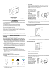
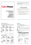
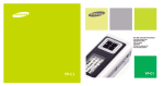
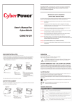
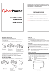
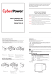
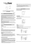
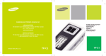
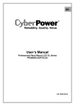
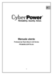
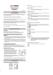
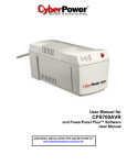
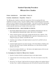
SPECIFICATION
Back Panel
Buzzer ON/OFF Switch
OFF
CyberShield UPSs are designed to provide a local power solution for
cable telephony, wireless local loop (WLL), and fiber to the home
(FTTH) broadband equipment.
ON
Model
Buzzer ON/OFF Switch
OFF
/ CS24U12V-12
INPUT: 100-240V~ 50-60Hz; 0.75A OUTPUT: 12V
CAUTION: RISK OF ELECTRICAL SHOCK. DO NOT
24W
/ CS30u12V-20
OUTPUT: 48V 50W
INPUT: 100-240V~ 50-60Hz ; 2.0A
CAUTION: RISK OF ELECTRICAL SHOCK. DO NOT
REMOVE COVER. NO USER SERVICEABLE PARTS INSIDE.
REFER SERVICING TO QUALIFIED SERVICE PERSONNEL.
Voltage Range
REMOVE COVER. NO USER SERVICEABLE PARTS INSIDE.
FOR USE IN A CONTROLLED ENVIRONMENT.
REFER SERVICING TO QUALIFIED SERVICE PERSONNEL.
REFER TO MANUAL FOR ENVIRONMENTAL CONDITIONS.
FOR USE IN A CONTROLLED ENVIRONMENT.
REFER TO MANUAL FOR ENVIRONMENTAL CONDITIONS.
FCC CLASS B VERIFIED
FCC CLASS B VERIFIED
68FG
E235457
Made In China
E235457
Contains sealed nonspillable lead acid battery.
Must be properly recycled or disposed.
CS24U12V-12
Made In China
47 - 70 Hz
Output
On Battery Output Voltage
CS24U12V / CS24U12V-12
IMPORTANT SAFETY WARNINGS
(SAVE THESE INSTRUCTIONS)
This manual contains important instructions regarding the installation and operation of this device.
Read this manual thoroughly before attempting to unpack , install or operate this device
User’s Manual for
CyberShield
CAUTION! The battery can energize hazardous live parts inside even when the AC input power is
disconnected.
CAUTION! To prevent the risk of fire or electric shock, install in a temperature and humidity
controlled indoor area, free of conductive contaminants. (Please see specifications for
acceptable temperature and humidity range).
CS30U12V-20
Buzzer On/Off Switch : The default position of the buzzer switch is OFF. If you want to enable this
function, there is a button inside the hole, please insert a paper clip or small pointed object into the
hole and press the button. In case of utility failure (on battery ), it will emit a long beep. In case of
low battery, it will emit a short beep.
COMMUNICATION SIGNALS
The communication signals of this unit are isolated from the internal circuitry via open collector optocoupled transistors. The connection “SIG RTN” (Signal Return) is a common return point for all
communication signals. In the typical application, the attached equipment digital ground connects to
Signal Return, and pull-up resistors turn the open collector signals into logic levels.
CS24U12V
CS24U12V-12
CS30U12V-20
CAUTION! To avoid electric shock, turn off the unit and unplug it from the AC power source before
servicing the battery or installing a computer component.
12Vdc
24W
24W
Continuous Power Capability
Output Power Max
CS24U12V
CS24U12V-12
CS30U12V-20
Battery
Battery Type
Numbers of Battery
Typical Recharge Time
Replaceable
Sealed, Maintenance Free Lead-Acid Battery
7.2AH/12V x 1 12AH/12V x 1
18Hours
24Hours
Yes
Yes
Warning Diagnostics
Indicators
Communication Interface
+ Voltage output
12V RTN
- Voltage output
SIG RTN
Signal return
ON BATTERY
Low when operating from utility line.
Open when operating from battery.
REPLACE
Low when battery is charged.
BATTERY
Open when battery fails the Self Test.
BATTERY
Low when battery is present.
MISSING
Open when battery is missing.
LOW BATTERY
AC, Output, Battery
Management
Yes
On Battery, Replace Battery, Battery Missing,
Message
12V
Low when battery is near full charge capacity.
20AH/12V x 1
42Hours
Surge Protection and Filtering
Auto-Charge
CS24U12V
CS24U12V-12
CS30U12V-20
30W
30W
> 75 %
Efficiency (at 75% Max Load)
Lightning / Surge Protection
CAUTION! To reduce the risk of electric shock, do not remove the cover, except to service the
battery. No user serviceable parts inside, except for the battery.
CS30U12V-20
85Vac - 264Vac (Universal Input)
Frequency Range
68FG
Contains sealed nonspillable lead acid battery.
Battery must be recycled or disposed of properly.
CS24U12V
Input
ON
Low Battery
Physical
Maximum Dimensions (L*W*D) 16.7cmx24cmx8.1cm 30cmx28cmx9.9cm
Weight (kg)
3.28
4.92
7.7
Environment
32oF - 104oF (0 - 40oC)
Operating Temperature
Operating Humidity
0 - 95% noncondensing within enclosure
Max Operating Elevation
Max Storage Elevation
Storage Temperature
10,000ft (3,000m)
50,000ft (15,000m)
5 F - 113oF (-15oC - 45oC)
o
Open when operating from a battery with < 20% capacity.
ENCLOSURE INSTALLATION
LIMITED WARRANTY
OPERATION
Carefully follow these instructions during installation of this device:
1.) Carry out the installation in a safe area that is free of excessive dust and has adequate airflow.
2.) Screws must be appropriate for total weight of the UPS and the mounting surface material.
3.) Do not operate the UPS where the temperature and humidity are outside the specified limits.
(Refer to specification in this manual.)
Connect: Equipment and Power
Step1. Plug the UPS power cord into the utility power cord inlet
Step2. Plug the UPS power cord into the wall outlet.
CyberPower warrants to you, the Initial Purchaser, that the Product will be free from defects in material and workmanship for three years from the date of original purchase, subject to the terms of this Limited
Warranty. This Limited Warranty gives you specific rights, and you may have other rights, which vary from State to State or Province to Province.
The UPS battery charges when it is connected to utility power. The battery charges
fully during the first 24 hours of normal operation. Do not expect full battery run
capability during this initial charge period.
COLD START
CS30U12V-20
The cold start feature is for applying power to the UPS and connected equipment when the UPS is
off and there is no utility power. Before using the cold start feature, please make sure the battery is
charged. To start the cold start feature, press the recessed cold start button with a small pointed
object.
Once the battery is disconnected, the connected equipment is not protected from power
outages.
Battery Cover
Release Tab
CS24U12V
CS24U12V-12
Step 1:
a. Remove the battery cover.
Step 2:
a. Unstrap strap from battery.
b. Slide battery off of the
shelf.
c. Disconnect battery cable
connector at chassis end.
BATTERY REPLACEMENT
Step 3:
a. Use the enclosed installation template to
mark an installation location for the unit.
b. Mount the unit on the wall with 2 mounting
screws into the keyhole slots.
c. Tighten the screws to secure the units.
d. Connect the battery connector and replace
the battery back.
This battery is hot-swappable. As long as utility power is on , you may leave the UPS and connected
equipment on while replacing a new battery.
Deliver spent batteries to a recycling facility or ship to the manufacturer in the
replacement battery packing material.
AC
OUTPUT
Color
Condition
Green
UPS is on utility power.
Yellow
Green
UPS is on battery power.
DC output power is provided by the battery or
utility power.
The battery is not connected or the battery
needs to be replaced.
Red
BATTERY
To be covered you must still be the owner of the Product at the time of the failure that results in the claim made under this Limited Warranty. Your sole and exclusive remedies are those provided by this
Limited Warranty. This exclusion of other express warranties applies to written and oral express warranties. CyberPower excludes any liability for personal injury. CyberPower excludes any liability for direct,
indirect, special, incidental, or consequential damages, whether for damage to or loss of property, loss of profits, business interruption, information or data. This exclusion applies even though damage or loss
is caused by negligence or other fault. NOTE: Some States or Provinces do not allow the exclusion or limitation of incidental or consequential damages, so the above limitation may not apply to you.
DO NOT USE FOR MEDICAL OR LIFE SUPPORT EQUIPMENT OR OTHER HIGH RISK ACTIVITIES.
CyberPower does not sell the PRODUCT for use in high-risk activities. The PRODUCT is not designed or intended for use in hazardous environments requiring fail-safe performance, including the operation
of nuclear facilities, aircraft navigation or communication systems, air traffic control, weapons systems, life support or medical applications or for use in any circumstance in which the failure of the PRODUCT
could lead directly to death, personal injury, or severe physical or property damage, or that would affect operation or safety of any medical or life support device (collectively, "High Risk Activities").
CyberPower expressly disclaims any express or implied warranty of fitness for High Risk Activities. CyberPower does not authorize use of any PRODUCT in any High Risk activities.
ANY SUCH USE IS IMPROPER AND IS A MISUSE OF A CYBERPOWER PRODUCT.
The Limited Warranty is governed by the laws of the United States and the State of Minnesota, without reference to conflict of law principles. The application of the United Nations Convention of Contracts for
the International Sale of Goods is expressly excluded
WARNING INDICATOR
Indicator
Any Implied Warranty of Merchantability or for Fitness for a Particular Purpose, if applicable to the Product, is limited in duration to three years. This provision shall NOT create any Implied Warranty or
Merchantability or of Fitness for a Particular Purpose that would not otherwise apply to the Product. NOTE: Some States and Provinces do not allow limitations on how long an implied warranty lasts,
so the above limitation may not apply to you.
FCC NOTICE:
Front Panel
PLUG-IN
BATTERY
HERE
This equipment has been tested and found to comply with the limits for a Class B digital device, pursuant to part 15 of the FCC Rules. These limits are designed to provide reasonable protection against
harmful interference in a residential installation. This equipment generates, uses and can radiate radio frequency energy and, if not installed and used in accordance with these instructions, may cause harmful
interference to radio communications. However, there is no guarantee that interference will not occur in a particular installation. If this equipment does cause harmful interference to radio or television reception,
which can be determined by turning the equipment off and on, the user is encouraged to try to correct the interference by one or more of the following measures: (1)Reorient or relocate the receiving antenna.
(2) Increase the separation between the equipment and receiver. (3) Connect the equipment into an outlet on a circuit different from that to which the receiver is connected. (4) Consult the dealer or an
experienced radio/TV technician for help.
CAUTION: Shielded signal cables must be used with this device to ensure compliance with Class B FCC limits.
CAUTION: Any changes or modifications not expressly approved by Cyber Power could void the authority granted by the FCC to operate this equipment.
TM
INTELLIGENT BACK-UP POWER
AC
OUTPUT
BATTERY
TM
CS30U12V-20
INTELLIGENT BACK-UP POWER
AC
OUTPUT
BATTERY
Battery Cover
Release Tab
Step 1:
a. Remove the battery cover.
Step 2:
a. Loosen the battery strap.
b. Disconnect battery cable connector
to remove battery.
c. Replace with new battery and
re-connect the battery connector.
For more information, please contact:
CyberPower Systems ( USA ), Inc. 4241 12th Avenue East, Suite 400, Shakopee, MN55379
CyberPower Systems ( EUROPE ), Inc.. Flight Forum 3545, 5657DW Eindhoven, The Netherlands
CS24U12V
CS24U12V-12
Step 3:
a. Tighten the battery strip and
close the battery cover.
CS24U12V / CS24U12V-12
Phone: (952)403-9500 Fax: (952)403-0009
E-mail: [email protected]
www.cpsww.com
eu.cyberpowersystems.com
CS30U12V-20
K01-3012000-01