1
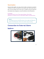
APW 2100 Manual
Accessory for T-eye Automated Drive Recorder
Specifically designed for Taxi applications
Main features:
The Model APW-2100 accessory module connects to the T-eye recorder
via special cable. The module also is connected to the vehicle’s battery,
providing a continuous source of power, and is also connected to the
Vehicle’s ignition (IGN) controlling the continuous record function of the
recorder. More importantly, this accessory module monitors the state of
the vehicle’s IGN: The unit records at full frame rate when the ignition is
turned on; and reduced the record frame rate to 1 fps when the engine is
turned off, continuing the recording but at a reduced frame rate to save
storage space, up to a predetermined shut of time as determined by the
programming of the module’s Dip-Switches (done at time of installation).
Additionally this module features a “Snapshot mode” sense wire. For use
primarily in taxi or limousine applications, when this module is connected
to the T-eye unit and in turn, the Orange wire associated with this
function is connected to either voltage generated by the taximeter when
in the “hired” mode, or other source of positive voltage, (example,
opening of the door), this “Snapshot Trigger” augments security. First”
The recorder captures 4 frames of video from the interior camera and
stores it in a “Snapshot” folder on the recorder’s SD card. The data in
this folder is not overwritten by the recorder; rather, an authorized
person removing the SD card and accessing this file via PC or laptop may
then only erase this file.
By sensing the state of the vehicle’s IGN; T-Eye may record for up to a
maximum of 19 hrs and 46 minutes after the engine had been turned off.
A distinct input is also provided to accept a manual alarm/event button.
This allows the driver to mark a scene of interest as an event. This event
trigger once detected records 1, 2 or 3 minutes prior to the event as well
1
as 1 minute after, saving this event data in an event file that is not erased
by the recorder. Time set by the software in the set up utility screen.
NOTE: The T-eye without this module will record video and /or audio
when the IGN is on, and stops recording when the IGN is turned off.
※NOTE
Use of this module does not impede the recorder from generating its
Pre-Event G-sensor/shock/accident/impact generated alarms.
Electrical specifications
Item
Input Power voltage
Input Signal voltage
Output Power voltage
Low Battery Voltage
Disconnect of recorder
Details
Min. 9V ~ Max. 36V
Min. 5V ~ Max. 36V
DC + 5.4V
Min. 12V(12V battery) or
Min. 24V(24V battery)
2
Product Details/Features:
Reduced Recording Rate
(Continued recording when engine is turned off):
With the vehicle’s IGN turned off, T-Eye records for a maximum of 19 hrs
and 46 minutes at a reduced rate of 1 frame per second (fps). Time is
dependent on the settings of the Dip-Switches of the accessory module
(set at time of installation). For taxi or limousine applications, this extends
the recorder’s recording time significantly between times that the vehicle
is either not in motion or with a fare. When the IGN is on, the recorder
will capture video at the standard 20 fps.
*NOTE: If the vehicle’s IGN is turned off, the IR illuminator does not work.
Low Battery Operation
(Low Voltage Disconnect):
The APW-2100 module with the engine turned off also checks the
vehicle’s battery voltage. If this drops to a point that is dangerously close
to preventing vehicle start-up, the APW-2100 will sense this and will then
will stop the recorder from operating or recording. This thereby prevents
the possibility of a totally discharged battery.
Snapshot function when a Taximeter is turned on (taxi
hired), or other user designated function (input).
To satisfy the requirement of taking pictures of all passengers in the
vehicle once the taximeter has been turned on (or other signal activated),
and also storing the visual data in a file that may not be overwritten by
the recorder, when this input is activated the recorder will save 4 frames
of the Interior Camera view to the Snapshot folder.
3
4
Features
Ignition sense IGN
APW 2100
Snapshot trigger
cable
T-eye Power cable
Power cable
+
External Input
Connect to T-eye
Time Setting
Fuse (2A)
5
Dip-Switch Set-Up for record shut
down delay time when engine is
turned off
Switch
no.1
Switch
no. 8
ON
OFF
Switch No.
(to on)
1
2
3
4
5
6
7
8
Function
Timer set-up for 1min
Timer set-up for 5mins
Timer set-up for 10mins
Timer set-up for 30mins
Timer set-up for 1hr
Timer set-up for 6hrs
Timer set-up for 12hrs
Low Voltage Disconnect of Recorder
(default)
(default)
6
Timer function
Using the above table, one may set the recorder to continue to record at
1 fps after the IGN is turned off, for the preset time. Each switch has its
own set time duration and if more time is needed, one may extend the
time duration by setting two or more Dip Switches to the ON position.
For example,
Switch no.6 and no.7 are on; Timer setup to 18hours. (6hrs+12hrs)
Switch no.5, no.6 and no.7 are on; Timer setup to 19hours. (1hr+6hrs+12hrs)
※NOTE
If all switches are set to the OFF position; the recorder will follow the
status of the IGN position. IGN is off, recorder stops recording.
Connection to External Alarm
button:
7
Connect the supplied external alarm button of the T-eye recorder to the
APW2100 using the 2.5mm connection provided. The supplied
momentary push button may be eliminated and replaced by a suitable
momentary pushbutton to the customer’s requirements, such as a switch,
this to match other switches located on a vehicle’s instrumentation panel.
This alarm button when activated records either 1,2 or 3 minutes of pre
event video and audio prior to the moment that the button was pushed
as well as 1 minute after; saved in an event file that may only be erased
once the SD card is removed and an authorized person using a PC or
laptop accesses this file.
8
Installation Instructions:
A. Connecting Power to the APW 2100 Module
STEP 1: Connect the BLACK WIRE (- line) of the supplied 2 conductor (red
and black) Power Cable to a source of Negative 12 VDC. It is always
recommend to run this to the Negative of the Battery or Main Negative
point of the vehicle’s fuse box. DO NOT USE A GROUNDING SCREW OR
CHASSIS GROUND FOR THIS.
STEP 2: Connect to RED WIRE (+ line) of the supplied two conductor (red
and black) power cable to a Source of + 12 or + 24 VDC of the vehicle. It is
always recommended to run this wire to the positive terminal of the
battery, with the fuse located at the + battery terminal.
※NOTE
The RED wire is connected to a source of + battery voltage even of the
ignition is turned off.
B. Connecting to the Vehicle’s Ignition (IGN)
Connect the YELLOW WIRE to a source of + power (+9 to +36 VDC) that is
always present when the vehicle’s engine is turned on (IGN), (with power
applied, this provides for full rate recording when the engine is running
and the vehicle is being driven. Providing full frame rate recording.
When the engine is turned off, and there is no voltage sensed on this wire,
the recorder will reduce its frame rate to 1 fps recording for the pre set
time as set by the Dip Switches.
※NOTE
Connect the YELLOW wire to a point on the fuse box of the vehicle which
supplies power ONLY when the vehicle is running.
9
C. Connecting the “Snap-shot” record trigger input
Connect the ORANGE wire to a source of power (+9 to +36 VDC)
whenever one wants to store 4 frames of video to the Snapshot Folder on
the SD card.
This trigger wire may be connected to a momentary push button switch
or the “taxi hired” output of the taxi fare meter. User may require the
installation of a simple SPDT relay to accomplish this. Any application of
power on this wire activates this function.
D. Enable/Disable the Low Voltage Battery Disconnect
Function
Set Dip-Switch No.8 to the on position to enable the low voltage
disconnect feature of the module to prevent accidental discharge of the
vehicle battery if the unit senses that the battery voltage is too low.
!CAUTION!
Always connecting to the power of the vehicle, connect to the Battery
Negative (Ground) first.
Connection to a source of +12 or 24 VDC power: Connect to the +
battery post of the vehicle’s battery or main + supply post of the
vehicle's fuse box. IF CONNECTING TO THE BATTERY, INSTALL THE
FUSE AT THE BATTER + POST.
IGN and Snapshot signal should be connected using a fuse located at
the power source.
10


![STATUTORY INSTRUMENTS S.I. No.[ • ] of 20[ • ] SMALL PUBLIC](http://vs1.manualzilla.com/store/data/005664657_1-1d833bc83c9d446d3d2ea05d8407eb41-150x150.png)