1
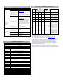
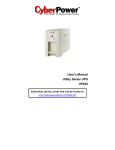
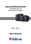
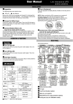
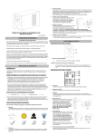
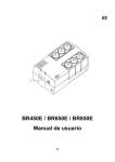
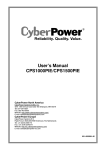
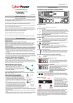
0E
◆ Power
Switch
Press the power button to turn the UPS ON or OFF.
eu.cyberpowersystems.com
◆ Power
Office Tower Series UPS
OP350TE/OP500TE
User Manual
On Indicator
This LED is illuminated when the utility condition is normal and the UPS outlets are
providing “clean power”, free of surges and spikes.
K01-0500E00-01
SAFETY WARNINGS
(SAVE THESE INSTRUCTIONS)
This manual contains important safety instructions. Please read and follow all instructions carefully
during installation and operation of the unit. Read this manual thoroughly before attempting to
unpack, install, or operate your UPS.
◆ Using
Battery Indicator
This illuminates during utility failure, indicating that the battery is supplying power to
the battery-power supplied outlets.
◆ Boost
Indicator
This LED indicates that the UPS is operating in automatic voltage regulation mode.
When the led is illuminated continuously, it indicates that input under-voltage and that
the UPS unit boosts input voltage.
This equipment can be operated by any individuals with no previous training.
The socket-outlet shall be installed near the equipment and easily accessible.
◆ Buck
Indicator
This LED indicates that the UPS is operating in automatic voltage regulation mode.
When the led is illuminated continuously, it indicates that input over-voltage and that
the UPS unit bucks the voltage.
During the installation of this equipment it should be assured that the sum of the leakage currents of
the UPS and the connected loads does not exceed 3.5mA.
Attention, hazardous through electric shock. Also with disconnection of this unit from the mains,
hazardous voltage still may be accessible through supply from battery. The battery supply should be
therefore disconnected in the plus and minus pole at the quick connectors of the battery when
maintenance or service work inside the UPS is necessary.
◆
Battery Backup and Surge Protection Outlets
Do not dispose of batteries in a fire, the battery may explode.
The UPS provides battery powered and surge protected outlets for connected
equipment to insure temporary uninterrupted operation during a power failure and
against surges and spikes.
Do not open or mutilate the battery or batteries, released electrolyte is harmful to the skin and eyes.
Do not replace the batteries.
INSTALLING YOUR UPS SYSTEM
◆
Surge Protection Outlets
UNPACKING
Inspect the UPS upon receipt. The box should contain the following:
®
UPS Unit; PowerPanel Plus Software Disk¯1; Serial Interface Cable (DB-9)¯1; Telephone
®
Cable¯1; Power Cord¯2; User Manual; PowerPanel Plus Software User Manual.
The UPS provides surge protected only outlet for connected equipments against
surges and spikes.
HOW TO DETERMINE THE POWER REQUIREMENTS OF YOUR
EQUIPMENT
1. Insure that the equipment plugged into the battery power-supplied outlets does not exceed the
UPS unit’s rated capacity (350VA/200W for OP350TE, 500VA/300W for OP500TE). If rated unit
capacities are exceeded, an overload condition may occur and cause the UPS unit to shut down
or the circuit breaker to trip.
2. If the power requirements of your equipment are listed in units other than Volt-Amps (VA), convert
Watts (W) or Amps (A) into VA by doing the calculations below. Note: The below equation only
calculates the maximum amount of VA that the equipment can use, not what is typically used by
the equipment at any one time. Users should expect usage requirements to be approximately
60% of below value.
◆ Serial
Port to PC
This port allows connection and communication from the DB-9 serial or USB port on
®
the computer to the UPS unit. The UPS communicates its status to the PowerPanel
Plus software. This interface is also compatible with the UPS service provided by
Windows 98, Windows ME, Windows NT, Windows 2000, Windows XP,
Windows Server 2003.
◆ Ethernet
TO ESTIMATE POWER REQUIREMENTS
1.
Watts (W) x 2.0 =
VA or
Amps (A) x 230 =
VA
2. Add the totals up for all pieces of equipment and multiply this total by 0.6 to calculate actual
requirements. There are many factors that can affect the amount of power that your computer
system will require. The total load that you will be placing on the battery-powered outlets should not
exceed 80% of the unit’s capacity.
HARDWARE INSTALLATION GUIDE
1. Connect the equipment to your UPS outlets. The IEC-IEC
power cords coming with the unit are used to connect your
computer and monitor to the UPS. Items such as copiers,
laser printers, vacuums, space heaters, or other large
electrical devices should not be connected to the UPS.
Please make sure that the total loads of your equipments are
less than the maximum total power load of your UPS.
2. Use your computer power cord to connect the UPS to a wall
outlet. Please avoid using extension cords and adapter plugs. (To maintain optimal battery charge,
leave the UPS plugged in at all times.)
3. Press the UPS power button to turn it on. The “Power On” indicator will be illuminated in “Green”.
4. Install your software and accessories. To use the software, simply connect the enclosed serial
interface cable to the serial port on the UPS and an open serial port on the computer.
BASIC OPERATION
FRONT PANEL AND REAR PANEL DESCRIPTION
(RJ-45) Network Protection Ports
These ports are the protection for your computer network cable.
TROUBLE SHOOTING
Problem
The UPS does not
perform expected
runtime.
The UPS will not
turn on.
Possible Cause
DEFINITIONS FOR ILLUMINATED LED INDICATORS
Solution
Batteries are not fully charged.
Recharge the battery by leaving the UPS
plugged in.
Battery is slightly worn out.
Contact Cyber Power Systems at
[email protected]
The on/off switch is designed to
prevent damage by rapidly
turning it off and on.
Turn the UPS off. Wait 10 seconds and then
turn the UPS on.
The unit is not connected to an
AC outlet.
The unit must be connected to a 220-240V
50/60Hz outlet.
The battery is worn out.
Contact Cyber Power Systems at
[email protected]
Mechanical problem.
Contact Cyber Power Systems at
[email protected]
Fuse is blown due to overload
Turn the UPS off and unplug at least one piece
connected equipment. Unplug the power cord of
the UPS then remove the fuse compartment
beneath the power inlet of the UPS and replace
the blown fuse with a spare one. Lock the
compartment back to the UPS. Connect power
cord then turn the UPS on. Make sure that your
spare fuse meets the specification: 6.3A, 250V,
5x10mm.
Outlets do not
provide power to
equipment
Batteries are discharged
Allow the unit to recharge for at least 4 hours.
Unit has been damaged by a
surge or spike.
Contact Cyber Power Systems at
[email protected]
The serial cable is not
connected.
Connect the serial cable to the UPS unit and
an open serial port on the back of the
computer. You must use the cable that came
with the unit.
The serial cable is connected to
the wrong port.
Try another serial port of your computer.
The unit is not providing battery
power.
Shutdown your computer and turn the UPS off.
Wait 10 seconds and turn the UPS back on.
This should reset the unit.
The serial cable is not the cable
that was provided with the unit.
You must use the cable included with the unit
for the software.
Using
Battery
On
Off
Off
On
Off
On
Fuse
Alarm
Off
Normal
Off
On
Off
Normal
Off
Off
Off
On
Normal
Off
Off
On
Off
Off
Normal
Two
Beeps
Off
On
Off
Off
Normal
Rapid
Beeps
Blown
Two
beeps or
rapid
beeps
Off
®
PowerPanel Plus
is inactive (all icons
are gray).
Condition
Power
On
Off
On/Off
On/Off
On/Off
On/Off
On/Off
On/Off
Normal/
Blown
Long
Beep
Normal
Max. boost 13% of input
voltage for output regulation
while input voltage is from
12% to 22% under nominal.
Max. buck 12% of input
voltage for output regulation
while input voltage is from
10% to 17% over nominal.
Utility Failure- The UPS is
providing battery power to the
Battery-Power Supplied outlets.
Utility Failure- The UPS is
providing battery power. The
rapid beeps indicate the battery
will run out of charge within a few
minutes.
Overload- Occurs in the Full-time
Surge Protection Outlets. Please
turn the UPS off and unplug at
least one piece of equipment from
the UPS. Replace the fuse with
a spare one then turn the UPS
on.
Overload- Occurs in the
Battery-power Supplied Outlets.
Turn the UPS off and unplug at
least one piece of equipment from
the UPS. Check the fuse and do
the replacement if necessary.
Turn the UPS on.
For more information, visit eu.cyberpowersystems.com or contact
CyberPower Systems B.V. Flight Forum 3545, 5657DW Eindhoven, The Netherlands
TEL: +31 (0)40 2348170, FAX: +31 (0)40 2340314, E-MAIL: [email protected]
CyberPower Systems Inc. (USA) 4241 12th Avenue East Suite 400 Shakopee, MN 55379, U.S.A.
Tel: +1 952 4039500, Fax: +1 952 4030009, E-MAIL: [email protected]
TECHNICAL SPECIFICATIONS
Entire contents copyright ©2004 CyberPower Systems B.V., All rights reserved. Reproduction in
®
Model
Capacity (VA)
Capacity (Watts)
Input
Input Voltage Range
Frequency Range
Output
On Battery Output
Voltage
On Battery Output
Frequency
Overload Protection
Surge Protection and Filtering
Lightning / Surge
Protection
Network Protection
Physical
Total # of UPS
Receptacles
Maximum Dimensions
Weight (Kg)
Battery
Sealed Maintenance
Free Lead Acid
Battery
User Replaceable
Typical Recharge
Time
Warning Diagnostics
Indicators
Audible Alarms
Environmental
Operating
Temperature
Operating Relative
Humidity
Communication
®
PowerPanel Plus
Software
Management
Auto-Charger
Auto-Restart
USB
OP350E
OP500TE
350VA
200W
500VA
300W
®
whole or in part without permission is prohibited. PowerPanel and PowerPanel Plus are
trademarks of CyberPower Systems (USA) Inc.
CyberPower warrants to you, the original purchaser, that CyberPower UPS will be free from defects
220-240Vac
50/60 Hz
in design, assembly, materials and workmanship for two years ( battery is only one year) from the
date of original purchase.
Simulated Sine Wave at 230Vac +/- 7%
50 Hz
On Utility: Fuse, On Battery: Internal Current Limiting
Yes
RJ45 (One In/One Out)
2
23.8cm*8.0cm*13.7cm
4.6
5.3
12V / 4AHx1
12V/4.5AHx1
Yes, Hot Swappable Battery Pack
8 Hours
Power On, Using Battery, Boost, Buck
On Battery, Low Battery, Overload
+32°F to 95°F ( 0°C to 35°C )
0 to 95% NON-CONDENSING
Windows 98/ME/2000/NT/XP, Server 2003
Yes
Yes
Yes
Any warranty services, please contact your local dealers or distributors.