1
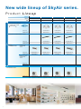
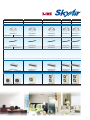
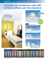
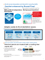
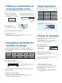
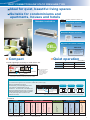
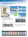
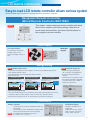
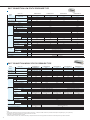
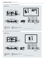
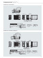
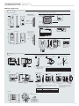
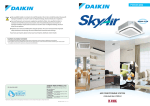
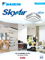
PCSID1424A
BEBAS CFC DAN HCFC
New wide lineup of SkyAir series.
Product Lineup
Series
09
13
18
Btu/h
9,200
13,000
18,000/17,700*
2.7
3.8
5.3/5.2*1
6.2
FCNQ13MV14
FCNQ18MV14
FCNQ21MV14
RNQ13MV14
RNQ18MV14
RNQ21MV14
FHNQ13MV14
FHNQ18MV14
FHNQ21MV14
RNQ13MV14
RNQ18MV14
RNQ21MV14
FDBNQ09MV14
FDBNQ13MV14
FDBNQ18MV14
FDBNQ21MV14
RNQ09MV14
RNQ13MV14
RNQ18MV14
RNQ21MV14
RNQ09MV14
RNQ13MV14
RNQ18MV14
RNQ21MV14
kW
21
1
21,000
CEILING MOUNTED
CASSETTE TYPE
Round Flow
Indoor unit
Outdoor unit
CEILING SUSPENDED TYPE
Pair
Indoor unit
Outdoor unit
DUCT
CONNECTION
LOW STATIC
PRESSURE
TYPE
Indoor unit
Outdoor unit
MIDDLE STATIC
PRESSURE
TYPE
Indoor unit
Outdoor unit
OUTDOOR UNIT
Outdoor unit
Note : *1Applicable to FDBNQ series. *2Applicable to FHNQ series. *3Applicable to FDMNQ series.
1
26
30
36
26,000
30,000
36,000/35,000*
7.6
8.8
10.6/10.4*2
12.5/12.3*2,3
14.1
FCNQ30MV14
FCNQ36MV14
FCNQ42MV14
FCNQ48MV14
RNQ30MY14
RNQ36MY14
FHNQ30MV14
FHNQ36MV14
FHNQ42MV14
FHNQ48MV14
RNQ30MY14
RNQ36MY14
RNQ42MY14
RNQ48MY14
FCNQ26MV14
RNQ26MV14
RNQ26MY14
FHNQ26MV14
RNQ26MV14
RNQ26MY14
FDMNQ26MV14
42
2
42,600/42,000*
48
2,3
48,000
RNQ48MY14
FDMNQ30MV14
FDMNQ36MV14
FDMNQ42MV14
FDMNQ48MV14
RNQ26MV14
RNQ26MY14
RNQ30MY14
RNQ36MY14
RNQ42MY14
RNQ48MY14
RNQ26MV14
RNQ26MY14
RNQ30MY14
RNQ36MY14
RNQ42MY14
RNQ48MY14
2
CEILING MOUNTED CASSETTE TYPE
Round Flow
Cassette air conditioner with 360°
uniform airflow sets the standard
FCNQ13/18/21/26/30/36/42/48MV14
Sound level
43/32dB(A)
High
Option
Low
FCNQ36M
(220V)
Accessory required for indoor unit.
Wired LCD remote controller
BRC1C61
Note: Remote controller cable not
included. Cables must be procured
locally.
Navigation Remote Controller
(Wired Remote Controller)
BRC1E62
Note: Remote controller cable not
included. Cables must be procured
locally.
Wireless LCD remote controller
A signal receiver must be added to the indoor unit.
BRC7F633F
Signal receiver unit
(Installed type)
Wireless remote controller and signal
receiver unit are sold as a set.
Features
3
Fresh air intake kit
• • • • • • • • • • • • •
Others
Anti corrosion treated
heat exchangers
Ultra long-life filter
High-efficiency filter
Options
DIII-NET communication
standard
Interlock control
Central remote control
External command
control
Group control by 1 remote
controller
Control by 2 remote
controllers
*5
Auto-restart
*4
Control features
Ceiling soiling prevention
•
Filter sign
•
*4Applicable to RNQ30-48M outdoor units
*5Applicable to RNQ13-26M outdoor units
*6For the outdoor units
Long-life filter
*3
Pre charged for
up to 10 m
*2
Pre charged for
up to 15 m
*2
Drain pump mechanism
*2
Work & Servicing
Cleanliness
Anti-bacterial air filter
Weekly schedule timer
*2
On/Off timer
Setpoint range set
*1
*1Applicable when wired remote controller is used
*2Applicable when BRC1E62 is used
*3Applicable when BRC1C61 is used
Off timer (programmed)
Setpoint auto reset
• • • • •
Two selectable
temperature-sensors
Remote controller
High ceiling application
Programme "Dry"
Switchable fan speed
(2 step)
Swing pattern selection
Auto swing
Comfort
*6
Avoids uneven temperature and discomfort caused by drafts.
Comfort enhanced by Round Flow!
360° airflow
Air movement is gentle with Round Flow
With uniform temperature Enhanced Comfort
distribution
360° airflow can
maintain comfort
even if air discharge
speed is lower.
Airflow
distribution
Creates uniform
comfort throughout
the space
If you raise the set
temperature by 1 to
1.5°C,and velocity is
decreased by 25%,
you still obtain the same
feeling temperature and
comfort.
Greater comfort
Improved energy saving
Adapts easily to the installation space.
Because air flows out from corner outlets, comfort spreads more widely.
Typical flow patterns
There are a total of 23 flow patterns.
All-round flow
3-way flow
(E.g., installed in
middle of ceiling)
(E.g., installed
near a wall)
L-shaped
2-way flow
(E.g., installed in
a corner)
Opposite
2-way flow
(E.g., installed in
a long room)
4-way flow also possible.
Note: Whatever the discharge direction, the same type of panel is used. If installing for other than all-round flow, an air discharge outlet sealing material (option) must be used to
close each unused outlet.
Operation sound increases when using 2-way or 3-way flow.
Grime prevention and bactericidal coating: Make cleaning easier.
External panels are treated with a coating that
Treated
Untreated
repels dirt.
surface
surface
To prevent dirt sticking to the
external panels, they have
been coated with a surface
treatment.
Resists
soiling
Grimy
surface
• Condition after exposure
to the smoke of 600
cigarettes in 1 m3
enclosed space.
Non-flocking flaps
Filter has anti-mould and bactericidal treatment
Condensation does not easily form on and dirt does not
cling to non-flocking flaps.
It is easy to clean.
Prevents mould and microorganisms growing out of the dust and
moisture that adheres to the filters.
4
CEILING MOUNTED CASSETTE TYPE
Fine square panels
Panel size is same for all models, FCNQ13-48M.
It is easy to maintain a neat appearance when
multiple units are installed.
950
mm
95
0m
Compact body and quiet operation
dB(A)
Indoor unit
High
Low
13/18M
21/26M
30/36M
42M
48M
31
35
43
44
44
28
28
32
34
36
Same for
all models
m
Optimal comfort and convenience
assured by 2 air discharge modes
Note: Air direction is set to the standard position when the unit is shipped from the factory.
The position can be changed from the remote controller.
Air direction
Desired
situation
Auto-swing
5-levels
air direction
setting
Standard setting
Setting to prevent soiling of ceiling*
Standard position to
prevent draft.
Recommended for shops with
light coloured ceilings that
must be kept spotless.
Auto-swing between
15° and 60°
Auto-swing between
25° and 60°
Settable to 5 different
levels between 15° and 60°
Auto air
direction control
Settable to 5 different
levels between 25° and 60°
The air direction is set automatically to the
memorised position of the previous air direction.
*Closing of the corner discharge outlets is recommended.
Suitable for high ceilings
Even in spaces with high ceilings, a comfortable airflow is carried down to
the floor level.
Criteria for ceiling height and number of air discharge outlets
(Ceiling height is reference value)
Number of air discharge outlets used
13-26M
Standard
Ceiling
High ceiling
height
High ceiling
All round 4-way 3-way 2-way
flow
flow
flow
flow
2.7 m 3.1 m 3.0 m 3.5 m
3.0 m 3.4 m 3.3 m 3.8 m
3.5 m 4.0 m 3.5 m -
30-48M
All round 4-way 3-way 2-way
flow
flow
flow
flow
3.2 m 3.4 m 3.6 m 4.2 m
3.6 m 3.9 m 4.0 m 4.2 m
4.2 m 4.5 m 4.2 m -
Note: Factory settings are for standard ceiling height and all-round flow.
High ceiling settings (1) and (2) are set with the remote controller by field setting.
Two selectable temperature-sensors
Both indoor unit and wired remote controller (option) contain temperaturesensors. Temperature sensing can be set at the unit or, to further improve
comfort level, closer to the target area at the wired remote control. This
feature must be set during commissioning by the technicians.
*Temperature-sensor on indoor unit must be used when the air conditioner is controlled from another room.
**Wireless remote controller does not have a temperature-sensor.
Switchable fan speed: High/Low
High setting provides maximum reach while low
setting minimises drafts.
On/Off timer
Operation starts when the preset time of the ON timer elapses and stops
when the preset time of the OFF timer elapses.
5
Round Flow
Note : Anechoic chamber
conversion value, measured
according to JIS parameters
and criteria. During operation
these values are somewhat
higher owing to ambient
conditions.
Quick and easy to install
Just 256 mm high. Installable in tight
ceiling spaces (13-26M)
256 mm *1
266 mm *2
*1 298 mm high with 30-48M
*2 308 mm high with 30-48M
Easy height adjustment
Each corner of the unit has an Adjuster Pocket that
lets you easily adjust the unit's suspended height.
Note: If the wireless remote control option is installed, a light receptor
unit is housed in one of the adjuster pockets.
All models can be installed without
using lifter because of the light weight.
Installable in
any direction
Since the orientation of
the intake grill can be
adjusted after installing,
the direction of the intake
grill lines can be unified
when multiple units
are installed.
Drain pump is equipped as standard
accessory with 850 mm lift.
850 mm
175 mm
Transparent drain socket
Because the drain socket is
transparent, after the drain piping
has been installed, it is easy to
check if the drain come out
through the socket.
Connection to a centralised control
system is available without option
CEILING SUSPENDED TYPE
Upgrade to a quiet and
compact system.
FHNQ13/18/21/26/30/36/42/48MV14
Sound level
44/40dB(A)
High
Low
FHNQ21M
(220V)
Wired LCD remote controller
Option
Accessory required for indoor unit.
Wired LCD remote controller
BRC1NU61
Note: Remote controller cable not
included. Cables must be procured
locally.
Wireless LCD remote controller
A signal receiver must be added to the indoor unit.
BRC7NU66
Signal receiver unit (Installed type)
Wireless remote controller and signal
receiver unit are sold as a set.
*3
•
Others
Anti corrosion treated
heat exchangers
*2
Control features
Auto-restart
•
Long-life filter
•
Work & Servicing
Pre charged for
up to 10 m
Cleanliness
Pre charged for
up to 15 m
*1
Remote controller
Anti-bacterial air filter
•
*1Installable on max. 3.5 m high ceiling
*2Applicable to RNQ30-48M outdoor units
*3Applicable to RNQ13-26M outdoor units
*4For the outdoor units
High ceiling application
•
Programme "Dry"
•
Switchable fan speed
(2 step)
Auto swing
Comfort
On/Off timer
Features
•
*4
6
Diffuses comfortable air
throughout the room
Auto-swing (up&down) brings comfort to the room.
Wide air discharge
openings produce a
spreading 100° airflow
Air is blown up to 50° in
the downward direction.
Quiet operation
Sound operation has been reduced on the exposed
ceiling suspended type unit.
(220V) dB(A)
Indoor unit
High
Low
13M
43
39
18/21M
44
45
48
49
40
40
42
43
26/30M
36/42M
48M
50°
100°
Note : Anechoic chamber conversion value, measured according to JIS
parameters and criteria. During operation these values are somewhat higher
owing to ambient conditions.
Uses quiet stream fan and other quiet
technologies.
Installable on
ceilings 3.5 m high
Turbulent flow Straightening
is reduced
plate
Quiet
stream fan
Switchable fan speed: High/Low
Programme "Dry"
Dehumidification is microprocessor controlled to prevent abrupt and
uncomfortable changes in air temperature.
Easier to maintain
Long-life filter lasts about 1 year*
* For dust concentration of 0.15 mg/m3
Installation flexibility for
freedom of design
Uniform height and depth. Compact design for
small-capacity models to meet tighter dimensional
constraints.
(mm)
Indoor unit
13M
18/21M
Height
Width
Depth
960
1,160
26/30M
36/42/48M
1,400
1,590
195
680
Two time settings (2500 hrs and 1250 hrs) are available to match
the installation environment. Maintenance time warning is
displayed on the remote controller (filter sign).
Non-flocking flap
Condensation does not easily
form on and dirt does not cling
to non-flocking flap.
It is easy to clean.
Non-flocking flap
Easy-clean, flat surfaces
It is easy to wipe dirt off the flat side and lower
surfaces of the unit.
For all maintenance tasks, access is
from bottom surface.
Flexible installation
The unit fits more snugly into tight spaces.
30 mm
or more
30 mm
or more
*Water used in the test-run can now be drained from
the air discharge opening rather than from the side as
was formerly the case.
All wiring and internal servicing can be done from
under the unit
Pipes more easily rigged
Plastic cover is used to conceal piping work holes.
When piping work the cover is easily taken off, and after piping work
easily attached again to conceal the holes.
7
Oil resistant grille
Oil-resistant plastic is used for the air suction grille.
This satisfies durability in restaurants and other
similar environments.
Note: Intended for use in salons, dining rooms, and ordinary sales
floors, this specification is not suitable for kitchens or other
harsh environments.
DUCT CONNECTION LOW STATIC PRESSURE TYPE
Ideal for quiet, beautiful living spaces
Suitable for condominiums and
apartments, houses and hotels
Option
FDBNQ09/13/18/21MV14
Accessory required for indoor unit
Wired LCD remote controller
BRC1C61
Navigation Remote Controller
(Wired Remote Controller)
BRC1E62
Sound level
Wireless LCD remote controller
43/40dB(A)
High
A signal receiver must be added to the indoor unit.
BRC4C64
Low
Signal receiver unit
(Separate type)
FDBNQ26M
(220V)
Compact
Wireless remote controller
and signal receiver unit
are sold as a set.
Quiet operation
(220V) dB(A)
Small, lightweight, and easy-to-install indoor unit.
Indoor unit
High
Low
09/13/18M
41
43
38
40
21/26M
or more
To prevent increased
operation sound,
avoid installing the air
suction grille directly
below the suction
chamber.
(Note)
Suction chamber
Air filter
[Duct connection]
Note : 270 mm is the minimum size.
Extra height is necessary for drain piping slope and insulation.
Simultaneous air conditioning of two rooms and ventilation grille (ventilation opening)
(This feature also applies to duct connection middle static pressure type.)
When air conditioning two rooms
simultaneously, the air discharged into each
room must be circulated back to the air
conditioner. To achieve this, a ventilation duct
should be installed for each room or one of the
indicated ventilation grilles should be installed
on the partitioning wall or under the door
between the rooms.
Door-installed
ventilation grille
Wall-installed
ventilation grille
Ventilation grille
Ventilation grille
Under-door cutout
Ventilates air through
the partitioning wall.
(See right)
Partitioning wall
Under-door cutout
Note: The under-door cutout method should be used only when there is a small volume of airflow.
Features
*3
*4
•
•
•
Anti corrosion treated
heat exchangers
*2
Others
Group control by 1 remote
controller
Pre charged for
up to 10 m
*2
Control by 2 remote
controllers
On/Off timer
*2
*3Applicable when BRC1C61 is used
*4For the outdoor units
Control features
Auto-restart
Off timer (programmed)
*2
Weekly schedule timer
*1
*1Applicable when wired remote controller is used
*2Applicable when BRC1E62 is used
Work & Servicing
Setpoint range set
Setpoint auto reset
•
Remote controller
Two selectable
temperature-sensors
•
Programme "Dry"
Switchable fan speed
(2 step)
Comfort
*4
8
DUCT CONNECTION MIDDLE STATIC PRESSURE TYPE
Unit can be mounted in the ceiling and air can
be delivered freely by duct.
Option
FDMNQ26/30/36/42/48MV14
Accessory required for indoor unit
Wired LCD remote controller
BRC1C61
Navigation Remote Controller
(Wired Remote Controller)
BRC1E62
Sound level
Wireless LCD remote controller
45/37dB(A)
High
A signal receiver must be added to the indoor unit.
BRC4C64
Low
Signal receiver unit
(Separate type)
FDMNQ36M
(220V)
Freedom of layout
Quiet operation
(220V) dB(A)
The duct system allows the efficient location
of discharge outlets in accordance with the
room layout
High
Low
26M
42
44
45
46
38
36
37
37
36M
Ordinary duct
(procured locally)
Air conditioner
305 mm
Indoor unit
30M
Duct connection is simpler with standard rear
intake chambers
Ordinary duct
(procured locally)
Wireless remote controller
and signal receiver unit
are sold as a set.
42/48M
Switchable fan speed: High/Low
Drain pipe connection can be done inside
the unit. Refrigerant and drain pipe outlets
are at the same opening.
325 mm
or more (Note)
Air discharge
Air intake
Note : 325 mm is the minimum size.
Extra height is necessary for drain piping slope and insulation.
Features
9
*3
*4
*5
•
•
•
Anti corrosion treated
heat exchangers
Pre charged for
up to 10 m
*2
Others
Group control by 1 remote
controller
Pre charged for
up to 15 m
*2
Control by 2 remote
controllers
On/Off timer
*2
*4Applicable to RNQ30-48M outdoor units
*5Applicable to RNQ26M outdoor units
*6For the outdoor units
Control features
Auto-restart
Off timer (programmed)
*2
Weekly schedule timer
*1
*1Applicable when wired remote controller is used
*2Applicable when BRC1E62 is used
*3Applicable when BRC1C61 is used
Work & Servicing
Setpoint range set
Setpoint auto reset
•
Remote controller
Two selectable
temperature-sensors
•
Programme "Dry"
Switchable fan speed
(2 step)
Comfort
*6
OUTDOOR UNIT
RNQ09MV14
RNQ13MV14
RNQ18MV14
RNQ21MV14
Quiet Operation
Fitted with Super Aero Grille
(Applies to RNQ30-48M)
RNQ26MV14
RNQ26MY14
RNQ36MY14
RNQ36MY14
RNQ42MY14
RNQ48MY14
Installation and
maintenance
Pre charged for up to 15 metres (Applies to RNQ30-48M)
To suppress turbulence
and achieve quiet
operation, the curved ribs
of the grille are optimised
to meet the outflow of air.
If refrigerant piping length does not exceed 10m (RNQ09-26M), 15m
(RNQ30-48M), there is no need for on-site gas charging.
Allowed refrigerant piping length and level difference
RNQ09/13M
RNQ18/21M
Equipped with scroll compressor
for quiet operation
(Applies to RNQ42-48M)
Smooth running, minimal
vibration, low operating
sound.
RNQ30-48M
10 m
15 m
30 m
30 m
Max. length
Max. level
difference
RNQ26M
10 m
Pre charged1
50 m
(Equivalent length
50m)
(Equivalent length
70m)
20 m
30 m
15 m
Note:
1
Additional refrigerant charging is required if the refrigerant pipe is longer than the
length.
4-direction piping offers greater
layout freedom (Applies to RNQ30-48M)
The outer panel for the piping connection
part of the front, right side and backside can
be removed and is easier for
post-installation piping work.
Separation
available
Durability
Operation sound
(In case of RNQ09-21M:220-240 V, RNQ26-36M:220 V/380 V,
240 V/415 V, RNQ42-48M:380 V, 415 V)
dB(A)
As the bottom frame is subject to corrosion,
corrosion-proof galvarium steel plate is adopted
to enhance the durability.
Outdoor unit
Sound level
RNQ09MV14
48
RNQ13MV14
49
RNQ18MV14
51
RNQ21MV14
52
RNQ26MV14/RNQ26MY14
54
RNQ30MV14/RNQ30MY14
55
Construction
RNQ36MV14/RNQ36MY14
54
Non-treated fin
Aluminium
RNQ42MY14
56
RNQ48MY14
58
Anti corrosion
treated heat
exchangers
Hydrophilic film
Aluminium
Corrosion resistant
acrylic resin
Heat exchange fins provided with anti-corrosion
treatment (Applies to RNQ09-26, 36-48M)
To achieve increased durability by improved resistance to salt corrosion and
atmospheric pollution, Anti corrosion treated heat exchangers (with special
acryl pretreatment) are used for the heat exchanger of the outdoor unit.
10
Simple system provides a diverse assortment of control modes.
Control
pattern
Applicable
model
Control by 1
remote
controller
(Basic system)
Control by 2
remote
controllers
For control from
2 locations such
as in room and
control room,
exits, etc.
Wired remote controller
FCNQ
Wireless remote controller
Non-polar, double-core
(max. wiring length 500 m)
Signal receiver unit installed
on indoor unit
Control by 1 wireless remote
controller and 1 wired remote
controller (See note 2, 3)
FDBNQ
Connects 2 wired remote
controllers (See note 1)
Signal receiver unit installed
on indoor unit
Automatic address setting function
Automatic address setting function
FDMNQ
Group
control
For
simultaneous
control of up to
16 indoor units.
Signal receiver unit installed
on 1 indoor unit
Control by
external
command
Operation and
surveillance is
carried out using
the contact signal
from the operation
control box in the
building
surveillance
(security) room.
Centralised
remote
control
Centralised
control of up to
64 indoor
groups from
remote location
up to 1 kilometer
away.
Optional wiring adaptor for
electrical appendices is necessary
Central remote controller (option)
Central remote controller (option)
FCNQ only
Heat Reclaim
Ventilator
Heat Reclaim
Ventilator
Link by remote
controller group
control.
Interlock
control
with Heat
Reclaim
Ventilator
Optional wiring adaptor for
electrical appendices is necessary
Can be operated simultaneously
or independently by remote controller
(set by ventilation mode)
Can be operated simultaneously
by remote controller
(set by ventilation mode)
Central remote controller (option)
Zone link control
by centralised
control.
Central remote controller (option)
Heat Reclaim
Ventilator
Heat Reclaim
Ventilator
Heat Reclaim Ventilator for indoor units within
a zone are operated by interlocking Can also
be operated independently by remote
controller.
Heat Reclaim Ventilator for indoor units within a
zone are operated by interlocking
Note: 1BRC1E62 can connect to BRC1E62 only.
2
It is not possible to use two wireless remote controllers.
3
BRC1E62 cannot connect to wireless remote controller.
Easily adaptable to large-scale, high-function,
centralised remote control system.
Central remote controller
DCS302CA61 (Option)
Centralised control, with setting as
simple as it is with a standard
remote controller, of up to 64 groups
(1,024 indoor units) is possible.
11
Unified on/off controller
DCS301BA61 (Option)
Centralised control of on/off by
group or all at once for up to 256
indoor units.
FCNQ series only
Schedule timer
DST301BA61 (Option)
Unified control of weekly schedule
for up to 1,024 indoor units.
Schedule timer sets on/off time in 1 minute units
to be executed twice a day for a week at a time.
DCS601C51 (Option)
With its high functionality, the full
colour “all-in-one” graphic controller
facilitates management of SkyAir
System in a variety of ways.
LCD REMOTE CONTROLLER
Optional accessory
Easy-to-read LCD remote controller allows various system
Remote controller options are shown on the page introducing each indoor unit model.
Navigation Remote Controller
(Wired Remote Controller BRC1E62)
This simple, modern designed remote controller with fresh
white colour matches your interior design. Operation is
much easier and smoother, just follow the indications on
the navigation remote controller.
NEW
Clear Display
Backlight
display
Dot matrix display
A combination of fine dots
enables various icons.
Large text display is easy to
see.
Energy saving
NEW
Setpoint auto reset
NEW
- Even if the set temperature is changed, it returns to the preset temperature
after apreset period of time.
- Period selectable from 30min/60min/90min/120min.
Restaurant sample
Restaurant opened
Temperature is set to 27ºC
Full tables at lunchtime
Then is lowered to 24ºC for
crowded room
27 °C
Off timer (programmed)
After 30 minutes*
Automatically returns to preset
temperature (27ºC)
Returns to
24 °C
27 °C
automatically
Setpoint range set
- Saves energy by limiting the
min. and max. set temperature.
- Avoids excessive heating or
cooling.
- This function is convenient when
the remote controller is installed
at a place where any number of
people may operate it.
*Setting possible for after 30, 60, 90, and 120
minutes.
- Sets and saves setting for an increment of time that automatically turns off air
conditioner after a preset period of time for each time operation starts.
- Period can be preset from 30 to 180 minutes in10-minute increments.
Convenience
Weekly schedule
- 5 actions per day can be scheduled for each day
of the week.
- The holiday function will disable schedule timer
for the days that have been set as holiday.
NEW - 3 independent schedules can be set.
Multilingual display
Display is available in 11
languages.
(English, German, French, Spanish,
Italian, Portuguese, Greek, Dutch,
Russian, Turkish, and Polish).
(e.g. summer, winter, mid-season)
12
control configurations and can control multiple indoor units.
Wired LCD remote controller
Easy to read because of large LCD screen.
The rubber switch and the
oil-resistant plastic casing are
adopted for durability.
Only 17 mm thick. Can be
installed either recessed or
exposed.
Wired remote controller has
built-in temperature-sensor
(Applies to wired remote controllers (BRC1C61/1E62))
Enables temperature sensing closer to target
area for improved comfort. (When using remote
control from another room, temperature-sensor in
indoor unit's air inlet must be selected.)
Facilitates maintenance and repair
All initial settings can be set from the remote
controller. After interior construction is complete,
ceiling mounted cassette type can be remotely set
without having to use stepladder access for
manual setting.
BRC1C61
LCD wireless remote controller
The wireless remote controller is
supplied in a set with a signal
receiver.
Signal receiver unit is contained
inside decoration panel or indoor
unit.
BRC7F633F
Wireless remote
controller
Signal receiver unit
(For ceiling mounted
cassette type)
Shape of signal receiver unit
differs according to the indoor
unit.
Note: The signal receiver unit shown in the
photograph is for mounting inside
the decoration panel of the ceiling
mounted cassette type.
Setting contents: High ceiling use, air direction, filter type, address for
centralised control (group control address is set automatically).
Remote controller is equipped with model name
and failure display functions. This facilitates
service in the unlikely event of a malfunction.
(Applies to wired remote controller (BRC1E62))
Ceiling mounted cassette type shares
common control with Heat Reclaim
Ventilator and the other Daikin
air-conditioning units, thus simplifying
interlocking operations.
Easily adaptable to large-scale, high-function,
centralised remote control systems.
Installing and connecting control wiring between
SkyAir and other Daikin air-conditioning equipment
is easy.
Wireless remote controller for each indoor unit type
CEILING MOUNTED CASSETTE TYPE
BRC7F633F
CEILING SUSPENDED TYPE
BRC7NU66
DUCT CONNECTION LOW STATIC PRESSURE TYPE
BRC4C64
DUCT CONNECTION MIDDLE STATIC PRESSURE TYPE
BRC4C64
LCD panel shows operating status in letters, numbers, and motion.
Airflow / swing display
Preset temperature / operation mode display
Programming time display
Self-diagnosis function
13
Displays auto-swing operating status and setting position of air discharge angle.
Displays preset room temperature and operating status (fan, dry, cool).
Operation start and stop time can be set for individual timers up to 72 hours. The LCD also shows
when it is time to clean the filter, when changeover is under centralised control, and ventilation/cleaning.
Monitors operating status within the system covering 40 items, and displays a message to indicate as soon as a malfunction occurs.
Abundance of functions that provide comfortable
air-conditioning in stores and offices.
Note: Some features only available on selected models. See model pages for full list of features applicable to each unit.
Comfort
Auto-swing
Delivers comfortable
air-conditioning to all areas, near
to and far from the
air-conditioner.
High-ceiling application
The air flow direction can be
fixed at your desited angle
by the remote controller.
Delivers air-conditioning comfort all the way down to the floor
in air-conditioning zones with high ceilings.
Swing pattern selection
(standard, ceiling soiling prevention)
You can freely set 2 air discharge setting by remote controller.
(1) Standard setting
(2) Ceiling soiling prevention
setting
Switchable fan speed
High setting provides maximum reach while low setting
minimises drafts.
Programme "Dry"
Dehumidification is microprocessor controlled to prevent
abrupt and uncomfortable changes in air temperature. Useful
for reducing uncomfortable humidity without uncomfortable
cooling of the room.
Note:When units are installed on high ceilings, depending on the model,
various restrictions concerning maximum height, air discharge direction,
and choice of options may apply.
Two selectable temperature-sensors
Temperature-sensors are included in the indoor unit and
optional wired remote controller. Temperature sensing closer
to target area is possible to further increase the comfort level.
Use the temperature-sensor in
the indoor unit when controlling
air conditioning from another
room.
Note: Wireless remote controllers have no
temperature-sensor.
Remote Controller
Setpoint auto reset
Even if the set temperature is changed, it returns to the preset
temperature after a preset period of time.
Setpoint range set
Saves energy by limiting the minimum and maximum set
temperatures. Avoids excessive heating and cooling.
Off timer (programmed)
Sets and saves setting for an increment of time that
automatically turns off air conditioner after a preset period of
time for each time operation starts.
On/Off timer
Operation starts when the preset time of the ON timer elapses
and stops when the preset time of the OFF timer elapses.
Weekly schedule timer
Up to five operation ON/OFF settings can be programmed per
day for each day of the week. Not only can the time be set for
the operation ON setting, but also the temperature.
Cleanliness
Anti-bacterial air filter
The Air filter has a anti-bacterial treatment to help prevent the growth of bacteria and mould on it.
14
Note: Some features only available on selected models. See model pages for full list of features applicable to each unit.
Work and Servicing
Drain pump mechanism
Steeper gradient realises more
efficient condensate drainage.
High-lift is especially useful for
long lengths of drain piping.
Pre charged for up to 15 metres
If refrigerant piping length does not exceed 15 m, there is no
need for on-site gas charging.
*Applicable to RNQ30-48M.
RNQ09-26M : 10 m
Filter sign
The filter sign warns you when it is time to clean the filter.
*When using a wired remote controller the sign is displayed in the LCD.
When using a wireless remote controller the filter sign lamp illuminates on
the signal receiver unit.
Ceiling soiling prevention function
Daikin's innovative air discharge mechanism keeps airflow
away from the ceiling. Ceiling cleaning is less frequently
required.
Long-life filter
Maintenance is not required for one year.
The filter is washable and can be reused.
Control features
Auto-restart
If there is a power outage while the equipment is operating,
operations will restart in the same mode as before the power
cut when electricity is restored.
External command control
Operation and surveillance is carried out using the contact
signal from the operation control box in the building
surveillance (security) room.
*An option is required.
Control by 2 remote controllers
Using 2 remote controllers you can operate the equipment
locally or from a remote location.
Note: When a wireless remote controller is used, remote control by two
remote controllers is not possible.
Group control by 1 remote controller
You can turn up to 16 indoor units on/off with a single remote
controller. (When using connected indoor units, the settings
must all be the same and on/off will be simultaneous.)
Central remote control
Optional central remote controller enables centralised control of
up to 1024 indoor units (64 groups) from up to 1 kilometer away.
Interlock control
Enables interlocking control with external equipment such as
Heat Reclaim Ventilator.
DIII-NET communication standard
Standardly equipped interface enables connection to
centralised control system without need of an adaptor.
Options
High-efficiency filter unit
Two types are available: 65% and 90% colorimetry.
Ultra long-life filter
Requires no maintenance for about 4 years* (10,000h) in
stores and offices.
*For dust concentration of 0.15 mg/m3
Fresh-air intake kit
You can provide air-conditioning with fresh air from outside.
Convenient for places where a ventilation fan cannot be
installed.
Note: *Connecting ducts, insect nets, fire dampers, air filters, and other parts
should, as required, be procured locally.
**Outside Air fan interlocked with air conditioning unit is necessary. Optional
PCB(KRP1C63)is required for interlocking.
***It is recommended that the volume of outdoor air introduced through the kit
is limited to 10% of the maximum airflow rate of the indoor unit. Introducing
higher quantities will increase the operating noise and may also influence
temperature sending.
Others
Anti corrosion treated heat exchangers
To achieve increased durability by improved resistance to salt corrosion and atmospheric pollution, coated Anti corrosion treated
heat exchangers (with special acryl pretreatment) are used for the heat exchanger of the outdoor unit.
In high corrosive areas, regular maintenance needs to be carried out.
15
SPECIFICATIONS
CEILING MOUNTED CASSETTE TYPE
13
18
21
26
30
36
42
48
FCNQ13MV14 FCNQ18MV14 FCNQ21MV14 FCNQ26MV14 FCNQ30MV14 FCNQ36MV14 FCNQ42MV14 FCNQ48MV14
Indoor unit
Model
Name
V14
Outdoor unit
Power supply
Y14
V14
Y14
kW
Btu/h
kW
W/W
Outdoor unit
Cooling capacity1,2
Cooling1
Power consumption
COP
Indoor
Colour
unit
---------
---------
Sound level (H/L)3
Unit
Decoration panel
Unit
Decoration panel
Certified Operation range
Colour
Type
Compressor
Motor output
Machine
weight
Refrigerant charge (R-410A)
Dimensions (HXWXD)
Machine weight
Certified Operation range
Liquid (Flare)
Gas (Flare)
Drain
Max. interunit piping length
13/10
459/353
31/28
°CWB
kW
kg
m
Indoor unit
V14
Outdoor unit
Y14
V14
Y14
kW
Btu/h
kW
W/W
Outdoor unit
Cooling capacity1,2
Power consumption
COP
Indoor
unit
Cooling1
Colour
Airflow rate (H/L)
33/22.5
1,165/794
44/34
298X840X840
44/36
24
5.5
14 to 23
0.9
14 to 25
Ivory white
Hermetically sealed rotary type
1.8
2.2
1.4
Hermetically sealed scroll type
3.75
4.5
2.7
1.2
1.4
1.5
2.0
1.9
3.2
2.7
3.2
(Charged for 10 m) (Charged for 10 m) (Charged for 10 m) (Charged for 10 m) (Charged for 15 m) (Charged for 15 m) (Charged for 15 m) (Charged for 15 m)
49
550X765X285
36
---------
o/ 12.7
51
52
595X845X300
40
49
----------------19.4 to 46
o/ 6.4
o/ 18.0 (Hole)
30
10
15
54
735X825X300
56
56
55
990X940X320
--------74
o/ 15.9
VP25 (I.Do/ 25XO.Do/ 32)
54
--------103
21 to 46
o/ 9.5
56
1,345X900X320
--------107
30
(Equivalent length 50)
o/ 26.0 (Hole)
50
(Equivalent length 70)
20
30
58
--------111
Sound level (H/L) (220 V)3
Colour
Compressor
Type
Motor output
kW
Refrigerant charge (R-410A)
kg
Sound level3
Dimensions (HXWXD)
Machine weight
Certified operation range
Piping
connections
Liquid (Flare)
Gas (Flare)
Drain
Indoor unit
Outdoor unit
Max. interunit piping length
Max. installation level difference
Heat insulation
26
30
36
42
48
13
18
21
FHNQ13MV14 FHNQ18MV14 FHNQ21MV14 FHNQ26MV14 FHNQ30MV14 FHNQ36MV14 FHNQ42MV14 FHNQ48MV14
RNQ13MV14 RNQ18MV14 RNQ21MV14 RNQ26MV14
---------
---------
V14
Y14
dB(A)
mm
kg
kg
°CDB
mm
mm
mm
mm
3.8
13,000
1.58
2.40
0.9
22-23/19-20
777-812/671-706
44/40
195X1,160X680
26
14 to 23
1.4
--------------------------------RNQ26MY14 RNQ30MY14 RNQ36MY14 RNQ42MY14 RNQ48MY14
--------7.6
26,000
2.65
3 Phase, 380–415 V, 50 Hz
8.8
10.4
12.3
30,000
35,000
42,000
4.51
3.07
3.64
2.73
2.86
2.87
White
26-27/22-23
918-953/777-812
45/40
195X1,400X680
32
14.1
48,000
5.51
2.56
42-44/24-26
38-40/23-25
1,341-1,412/812-883
1,483-1,553/847-918
48/42
49/43
195X1,590X680
35
14 to 25
Ivory white
Hermetically sealed rotary type
1.8
2.2
Hermetically sealed scroll type
3.75
4.5
2.7
1.2
1.4
1.5
2.0
1.9
3.2
2.7
3.2
(Charged for 10 m) (Charged for 10 m) (Charged for 10 m) (Charged for 10 m) (Charged for 15 m) (Charged for 15 m) (Charged for 15 m) (Charged for 15 m)
49
550X765X285
36
---------
o/ 12.7
51
52
595X845X300
40
49
----------------19.4 to 46
o/ 6.4
o/ 18.0 (Hole)
30
m
m
---------
1 Phase, 220–240 V, 50 Hz
--------5.3
6.2
18,000
21,000
2.38
2.04
2.60
2.60
m3/min
16/cfm
565/43/39
dB(A)
mm
195X960X680
kg
24
°CWB
Dimensions (HXWXD)
Machine weight
Certified operation range
Outdoor
unit
32/20
1,130/706
43/32
Both liquid and gas piping
CEILING SUSPENDED TYPE
Power supply
----------
14.1
48,000
5.04
2.80
50X950X950
Heat insulation
Model
Name
7.6
26,000
2.53
3.00
21
mm
mm
m
Max. installation level difference
---------
---------
21/13.5
741/477
35/28
19.5
°CDB
mm
mm
Indoor unit
Outdoor unit
---------
3 Phase, 380–415 V, 50 Hz
8.8
10.6
12.5
30,000
36,000
42,600
2.73
3.31
4.15
3.22
3.20
3.01
256X840X840
mm
kg
kg
dB(A)
mm
V14
Y14
---------
Fresh white
kg
Sound level3
---------
RNQ26MY14 RNQ30MY14 RNQ36MY14 RNQ42MY14 RNQ48MY14
1 Phase, 220–240 V, 50 Hz
--------5.3
6.2
18,000
21,000
1.89
2.21
2.80
2.80
3.8
13,000
1.24
3.07
m3/min
cfm
dB(A)
mm
Dimensions
(HXWXD)
Piping
connections
---------
Unit
Decoration panel
Airflow rate (H/L)
Outdoor
unit
RNQ13MV14 RNQ18MV14 RNQ21MV14 RNQ26MV14
10
15
54
735X825X300
56
56
55
990X940X320
--------74
VP20 (I.Do/ 20XO.D o/ 26)
30
(Equivalent length 50)
20
Both liquid and gas piping
54
--------103
21 to 46
o/ 9.5
56
1,345X900X320
--------107
58
--------111
o/ 15.9
o/ 26.0 (Hole)
50
(Equivalent length 70)
30
Note :
1
Rated cooling capacities are based on the following conditions: Indoor temp., 27°CDB, 19.0°CWB; outdoor temp. 35°CDB, 24°CWB. Equiv. refrigeration piping, 7.5 m (horizontal).
2
Capacities are net, including a deduction for cooling for indoor fan motor heat.
3
Anechoic chamber conversion value, measured according to JIS parameters and criteria. During operation these values are somewhat higher owing to ambient conditions.
16
DUCT CONNECTION LOW STATIC PRESSURE TYPE
Model
Name
Outdoor unit
Power supply
Power consumption
COP
Colour
Indoor
Fan
Outdoor
unit
13
FDBNQ13MV14
V14
RNQ09MV14
RNQ13MV14
Y14
---------
V14
Y14
kW
Btu/h
kW
W/W
Outdoor unit
Cooling capacity1,2
unit
09
FDBNQ09MV14
Indoor unit
Cooling1
Rated external static pressure3
mmH2O
Sound level (H/L) (220 V)4
dB(A)
mm
Dimensions (HXWXD)
kg
Machine weight
Certified Operation range
°CWB
Colour
Type
Compressor
Motor output
kW
Refrigerant charge
kg
(R-410A)
Sound level4
Dimensions (HXWXD)
Machine weight
Certified Operation range
Liquid (Flare)
Gas (Flare)
Indoor unit
Drain
Outdoor unit
Max. interunit piping length
Piping
connections
kg
°CDB
mm
mm
mm
mm
m
3.8
13,000
1.28
2.97
2.7
9,200
0.86
3.14
Model
Name
Power supply
Cooling capacity1,2
unit
Outdoor
unit
Fan
Cooling1
Ivory white
Hermetically sealed rotary type
0.9
1.4
0.65
1.8
0.9
(Charged for 10 m)
1.2
(Charged for 10 m)
1.4
(Charged for 10 m)
1.5
(Charged for 10 m)
48
49
51
52
550X765X285
35
----------
36
----------
595X845X300
40
---------19.4 to 46
o/ 6.4
o/ 12.7
3/4B (I.Do/ 21.6XO.Do/ 27.2)
o/ 18.0 (Hole)
o/ 9.5
o/ 15.9
30
10
15
Both liquid and gas piping
30
FDMNQ30MV14
36
FDMNQ36MV14
42
FDMNQ42MV14
48
FDMNQ48MV14
RNQ26MV14
---------
---------
---------
---------
RNQ30MY14
RNQ36MY14
RNQ42MY14
RNQ48MY14
--------3 Phase, 380–415 V, 50 Hz
10.6
12.3
14.1
8.8
36,000
42,000
48,000
30,000
3.53
4.49
5.56
3.03
3.00
2.74
2.54
2.90
---------42
37
1,306
1,483
9.8
8.0
44/36
45/37
46/37
305X1,550X680
52
14 to 25
Ivory white
Hermetically sealed rotary type
Hermetically sealed scroll type
2.2
2.7
3.75
4.5
V14
Y14
kg
°CDB
mm
mm
mm
mm
m
m
23
812
8.5
42/38
305X1,350X680
43
2.0
(Charged for 10 m)
1.9
(Charged for 15 m)
3.2
(Charged for 15 m)
2.7
(Charged for 15 m)
3.2
(Charged for 15 m)
54
735X825X300
56
56
55
990X940X320
---------74
54
56
1,345X900X320
---------107
58
o/ 18.0 (Hole)
30
(Equivalent length 50 m)
20
---------103
21 to 46
o/ 9.5
o/ 15.9
3/4B (I.Do/ 21.6XO.Do/ 27.2)
o/ 26.0 (Hole)
50
(Equivalent length 70 m)
30
Both liquid and gas piping
Note :
1
Rated cooling capacities are based on the following conditions: Indoor temp., 27°CDB, 19.0°CWB; outdoor temp. 35°CDB, 24°CWB. Equiv. refrigeration piping, 7.5 m (horizontal).
2
Capacities are net, including a deduction for cooling for indoor fan motor heat.
3
Please see fan characteristic document in detail.
4
Anechoic chamber conversion value, measured according to JIS parameters and criteria. During operation these values are somewhat higher owing to ambient conditions.
17
49
----------
RNQ26MY14
dB(A)
mm
Certified Operation range
Liquid (Flare)
Gas (Flare)
Indoor unit
Drain
Outdoor unit
Max. interunit piping length
Max. installation level difference
Heat insulation
43/40
260X1,300X580
32
Y14
Rated external static pressure3
mmH2O
Sound level (H/L) (220 V)4
dB(A)
mm
Dimensions (HXWXD)
kg
Machine weight
Certified Operation range
°CWB
Colour
Type
Compressor
Motor output
kW
Refrigerant charge
kg
(R-410A)
Piping
connections
18/15
635/530
V14
m3/min
cfm
Airflow rate (H)3
Sound level4
Dimensions (HXWXD)
Machine weight
----------
V14 1 Phase, 220–240 V, 50 Hz
Y14
7.6
kW
26,000
Btu/h
kW
2.62
W/W
2.90
Outdoor unit
Power consumption
COP
Colour
Indoor
6.2
21,000
2.38
2.60
2.0
26
FDMNQ26MV14
Outdoor unit
5.2
17,700
2.06
2.52
41/38
260X900X580
25
14 to 23
DUCT CONNECTION MIDDLE STATIC PRESSURE TYPE
Indoor unit
---------
13/11
459/388
m
Max. installation level difference
Heat insulation
RNQ21MV14
---------
1 Phase, 220–240 V, 50 Hz
---------
dB(A)
mm
V14
Y14
21
FDBNQ21MV14
RNQ18MV14
---------
m3/min
cfm
Airflow rate (H/L)3
18
FDBNQ18MV14
---------111
OPTIONS
Indoor unit
CEILING MOUNTED CASSETTE TYPE
Name of option
Remark
Decoration panel
Sealing material of air discharge outlet
Panel spacer
Fresh air
Chamber
type
intake kit1
Without T-joint pipe and fan
With T-joint pipe, without fan
Direct installation type
2
Chamber connection kit
Insulation kit for high humidity
(Colorimetric method 65%)
High-efficiency filter
(including chamber)
(Colorimetric method 90%)
Replacement
(Colorimetric method 65%)
high-efficiency filter
(Colorimetric method 90%)
Filter chamber
Replacement long-life filter
Ultra long-life filter
Replacement ultra long-life filter
Branch duct chamber
Wireless type
Cooling only
Remote controller
Wired type3
Navigation Remote Controller
Wired type3
Central remote controller4
Unified ON/OFF controller4
Schedule timer4
Touch Controller4
Adaptor for wiring5
Wiring adaptor for electrical appendices5
Installation box for adaptor PCB
Remote sensor
Kit name
FCNQ13MV14 FCNQ18MV14 FCNQ21MV14 FCNQ26MV14 FCNQ30MV14 FCNQ36MV14 FCNQ42MV14 FCNQ48MV14
BYCP125K-W1
KDBH55K160F
KDBP55H160FA
KDDP55B160
KDDP55B160K
KDDP55X160
KKSJ55KA160
KDTP55K160
KDTP55K80
KAFP556B160
KAFP556B80
KAFP557B160
KAFP557B80
KAFP552B160
KAFP552B80
KAFP553B160
KAFP553B80
KDDFP55B160
KAFP551K160
KAFP55B160
KAFP55H160H
KDJP55B80
KDJP55B160
BRC7F633F
BRC1C61
BRC1E62
DCS302CA61
DCS301BA61
DST301BA61
DCS601C51
KRP1C63
KRP4AA53
KRP1H98
KRCS01-4B
Note: 1Refer to page 6 for the details.
2
Required for installing high-efficiency filter or ultra long-life filter.
3
Wiring for wired remote controller to be procured locally.
4
The indoor unit is equipped standardly with the interface adaptor for SkyAir series. An option is unnecessary.
5
Installation box for adaptor PCB (KRP1H98) is necessary.
Round flow type: List of optional parts required to achieve different flow patterns
For each flow pattern – all round, 4-way, 3-way, 2-way, branch duct connection – the compatibility of each independently installed option
(shown in the column on the left) to accessory options (listed across the top of each table) is shown in the cells where the relevant row and column intersect.
A circle (o) indicates compatibility, and a cross (x) indicates incompatibility. Any options not shown below are not suitable for independent or accessory installation.
All round flow 4-way flow
Independently installable optional parts
Optional accessory parts
Panel/grille related
Panel spacer1
Operation control related
Wireless remote controller
Auxillary function related
Fresh air intake kit (Chamber type)1,2
Fresh air intake kit (direct mount)
High-humidity operation kit
Filter related
High-efficiency filter2
Ultra-long-life filter2
Panel spacer1
o
o
o
x
o
o
Wireless
Fresh air intake kit Fresh air intake kit
remote controller (Chamber type)1,2
(direct mount)
o
o
o
o
o
o
o
o
x
x
o
o
o
o
x
o
o
o
High-humidity
operation kit
High-efficiency
filter2
x
x
x
x
o
x
o
o
o
o
o
x
Ultra-long-life
filter2
o
o
o
o
x
x
3-way flow 2-way flow
Independently installable optional parts
Optional accessory parts
Panel/grille related
Panel spacer1
Operation control related
Wireless remote controller
Auxillary function related
Fresh air intake kit (Chamber type)1,2
Fresh air intake kit (direct mount)
High-humidity operation kit
Filter related
Ultra-long-life filter2
Panel spacer1
o3
o3
o3
x
o3
Wireless
Fresh air intake kit Fresh air intake kit
remote controller (Chamber type)1,2
(direct mount)
o3
o
o
o
o
o3
o
x
x
o
o3
o
x
o
o
High-humidity
operation kit
High-efficiency
filter2
x
x
x
x
x
x
x
Ultra-long-life
filter2
High-humidity
operation kit
High-efficiency
filter2
Ultra-long-life
filter2
x
o
x
o
o3
o
o
o
x
Branch duct connection
Independently installable optional parts
Branch duct1
(Chamber type)
(Round duct type)
Optional accessory parts
1-way branch / unit 3-way flow
2-way branch / unit 2-way flow
1-way branch / unit 2-way flow
Panel spacer1
o
x
x
Wireless
Fresh air intake kit Fresh air intake kit
remote controller (Chamber type)1,2
(direct mount)
o
o
o
o
o
o
o
o
o
4
4
4
x
x
x
x
x
x
o
o
o
18
Indoor unit
CEILING SUSPENDED TYPE
Name of option
Remark
Replacement long-life filter
L-type piping kit (for upward direction)
Remote controller
Resin net
Wireless type
Wired type1
Kit name
FHNQ13MV14 FHNQ18MV14 FHNQ21MV14 FHNQ26MV14 FHNQ30MV14 FHNQ36MV14 FHNQ42MV14 FHNQ48MV14
KAF501DA56
KAF501DA80
KAF501DA112
KAF501DA160
KHFJ5F50
KHFJ5F60
KHFP5MA160
BRC7NU66
BRC1NU61
Note: 1Wiring for wired remote controller to be procured locally.
DUCT CONNECTION LOW STATIC PRESSURE TYPE
Name of option
Remote controller
Navigation Remote Controller
Remark
Wireless type
Wired type1
Wired type1
Kit name
FDBNQ13MV14
FDBNQ18MV14
BRC4C64
BRC1C61
BRC1E62
FDBNQ09MV14
FDBNQ21MV14
Note: 1Wiring for wired remote controller to be procured locally.
DUCT CONNECTION MIDDLE STATIC PRESSURE TYPE
Name of option
Remote controller
Navigation Remote Controller
Remark
Wireless type
Wired type1
Wired type1
FDMNQ26MV14
FDMNQ30MV14
Kit name
FDMNQ36MV14
BRC4C64
BRC1C61
BRC1E62
FDMNQ42MV14
FDMNQ48MV14
Note: 1Wiring for wired remote controller to be procured locally.
Outdoor unit
Name of option
Central drain plug
19
Kit name
------------------------RNQ09MV14 RNQ13MV14 RNQ18MV14 RNQ21MV14 RNQ26MV14
------------------------RNQ26MY14 RNQ30MY14 RNQ36MY14 RNQ42MY14 RNQ48MY14
------------KKP014A4
KKPJ5F180
DIMENSIONS
(Unit: mm)
CEILING MOUNTED CASSETTE TYPE
[FCNQ13-48MV14]
[FCNQ13-26MV14]
B
280
330
4
1
[FCNQ30-48MV14]
157
350
A
157
280
330
4
1
2
35 or less
(Note 4)
Connection position
of branch duct
(round shape type)
55
256
157
350
A
167
160
67
27-M4 Prepared hole
95
167
93
29
5
29
95
Connection position
of branch duct
(square-shaped type)
167
93
160
67
95
29
157
350
2x100=200 80
25
160
157
350
C/L
213
ø10
(kn 0
ock
hole
)
90
183
C arrow view
Required space
200mm or more
130
105
60
42
125
165
20 C/L
350
840
81 2x100=200 85
160
64
50
1500 or more 67
(required space) 160
From the floor side 2500 or more
For height installation
Hanging bolt
4-M8~M10
Connection position
of branch duct
(round shape type)
3
150
160
298
95
167
850
Adjustable(0~675)
Connection position
of branch duct
(square-shaped type)
175
29
50
40
160
288
10
340
80 2x100=200 80
160
55
80
2x100=200
25
213
Connection position
of branch duct
(round shape type)
Connection position
of fresh air intake kit
(direct installation type)
[FCNQ30-48MV14]
55
B arrow view
124
35 or less
(Note 4)
Connection position
of branch duct
(square-shaped type)
16-M4 Prepared hole
840
157
350
Connection position
of branch duct
(round shape type)
Connection position
of fresh air intake kit
(direct installation type)
90
256
C/L
80
60
20-M4 Prepared hole
5
130
150
42
105
2
55
16-M4 Hole
Connection position
of branch duct
(square-shaped type)
20-M4
Prepared hole
90
350
35 or less
(Note 4)
Connection position
of branch duct
(round shape type)
157
840
81 2x100=200 85
124
64
50
1500 or more
(required space) 160
From the floor side 2500 or more
For height installation
Hanging bolt
4-M8~M10
Connection position
of branch duct
(round shape type)
55
3
Connection position
85 of branch duct
(round shape type)
[FCNQ30-48MV14]
160
124
109
95
Connection position
of branch duct
(square-shaped type)
20-M4
Prepared hole
95
110
124
16-M4 Prepared hole
55 Connection position
of branch duct
(square-shaped type)
125
165
256
50
40
20 C/L
55
95
110
[FCNQ13-26MV14]
[FCNQ13-26MV14]
95
110
124
840
340
80 2x100=200 80
124
2x100=200
160
C/L
93
160
124
7
Connection position
of branch duct
(square-shaped type)
A arrow view
175
850
Adjustable(0~675)
B arrow view
6
Drain Connection
Side
81
16-M4 Hole
157
350
950
C
[FCNQ13-26MV14]
160
246
10
Note 2
Pipe Connection
Side
420
55
2x100=200
124
C/L
81
950
8
780(Hanging bolt pitch)
9
860~910(Ceiling opening space) (Note 4)
710(Hanging bolt pitch)
420
860~910(Ceiling opening space) (Note 4)
300
or less
[FCNQ30-48MV14]
Connection position
85 of branch duct
(round shape type)
80
[FCNQ13-48MV14]
90
196
ø10
(kn 0
ock
hole
)
C arrow view
1500mm or more
1500mm
or more
1500mm
or more
200mm
or more
1500mm or more
The necessary space is 500mm or more when the
air-outlet is blocked with the accessory.
Moreover when the corner areas are blocked
(both right and left of the blocked air outlet),
the necessary space is 200mm or more.
35 or less
(Note 4)
Connection position
of branch duct
(square-shaped type)
Notes:
1
Sticking location for manufacture's label
manufacture's label for indoor unit:
Suction grille inner side's electric components box's lid surface
manufacture's label for decoration panel :
Decoration panel's corner decoration cover inner surface
2
In case of using wireless remote controller, this position will be a signal receiver. Refer to the drawing of wireless remote controller
in detail.
3
When the temperature and humidity in the ceiling exceed 30˚C and RH 80% or the fresh air is inducted into the ceiling or the unit
continues 24 hour operation, an additional insulation (thickness 10mm or more of glasswool or polyethylene form) is required.
4
Though the installation is acceptable up to maximum of 910mm square ceiling opening, keep the clearance of 35mm or less
between the indoor unit and the ceiling opening so that
the panel overlap allowance can be ensured.
5
Please do not place the thing been damp and troubled under an indoor unit.
When the case where humidity is 80% or more, and the drain outlet are choked up and the air filter are dirty, dew may fall.
1
2
3
4
5
6
7
8
9
Liquid pipe connection
Gas pipe connection
Drain pipe connection
Power-source wiring and a unit
wiring connection
Connection wiring/remote control
wiring connection
Air-outlet
Suction grille
Corner decoration cover
Drain hose (accessory)
20
CEILING SUSPENDED TYPE
[FHNQ13/18/21/26/30/36/42/48MV14]
1550 1590
FHNQ42MV14
1550 1590
FHNQ48MV14
1550 1590
36
115 60
FHNQ36MV14
50
127
60
105
8
5
(Required space)
15
1
11
Position : Hole of wall for taking out in piping back
(View from the front)
80
90
155
40
5
195
55
13
6
300 or more
(Required space)
For height installation
From the floor side 2500 or more 155
Hanging bolt
4-M8~M10
30 or more
4
B
30 or more
(Service space)
(Service space)
The Front
Obstacle
Floor side
o/ 45
225
275
300
275
80
80
2
14
1 Air discharge grille
2 Air suction grille
3 Air filter
4 Gas pipe connection
5 Liquid pipe connection
6 Drain pipe connection
7 Earth terminal (Inside the electric components box)
8 Suspension bracket
9 Backward pipe and wiring connection opening lid
10 Upward pipe and wiring connection opening lid
11 Right side pipe connection
12 Left back drain pipe connection
13 Left side drain pipe connection
14 Right side drain pipe connection
15 Hole of wall for taking out in pipe back
16 Upward drain pipe connection
17 Upward gas pipe connection
18 Upward liquid pipe connection
6
3
55
Brand name plate
(Note.2)
Drain pipe connection VP20
(For left piping)
7
5
105
4
170
Notes:
1
Location of unit's Name plate : Bottom of fan housing inside the suction grille.
2
In case of using wireless remote controller, this position will be a signal receiver.
Refer to the drawing of wireless remote controller in detail.
3
The remote control code is the standard <about 3m outside the machine> attached.
(0.5mm2x2 wicks O.D. 5.4)(It is not attached to VRV.)
DUCT CONNECTION LOW STATIC PRESSURE TYPE
[FDBNQ09/13/18MV14]
900
151
500
10-M4 Holes
(All Around)
1
2
3
4
21
10 or more
271
Service space
2
4
Liquid pipe connection
Gas pipe connection
Drain pipe connection
Ground terminal
5
6
7
8
29
1
260
150
219
236
5
110
170
228
684
664
3×P150=450
134
107
164
260
50
126
755
(Suspension bolt pinch)
6
7
12-M4 Holes
(All Around)
Switch box
Control wiring intake (for remote controller)
Control wiring intake (for outdoor unit)
Suspension bracket
16
10
151
127 3×P.150=450
674
688
704
900
52
16
10
8
55
317
580
3
300 or more
167
3
500
(Suspension bolt pinch)
137
704
65
Position slit hole for taking out in piping back
(View from the front)
10
A
(Hanging position)
680
145 60
65
1360 1400
9
5
135 (Required space)
FHNQ30MV14
40 135
1360 1400
185
1120 1160
FHNQ26MV14
192
1120 1160
FHNQ21MV14
102
FHNQ18MV14
12
160
960
85
920
210
FHNQ13MV14
170
105
90
58
18 17 16 142
260
B
(Hanging
position)
A
Note: 1Location of unit's Name Plate: Chamber cap
DIMENSIONS
(Unit: mm)
DUCT CONNECTION LOW STATIC PRESSURE TYPE
[FDBNQ21MV14]
151
271
580
Service space
55
317
1300
1104
151
219
236
10
7
150
6
1
260
228
110
29
5
1088
1074
6×P.150=900
52
102
4
170
50
107
260
164
134
2
700
16-M4 Holes
(All Around)
1
2
3
4
10
16
1084
1064
6×P150=900
16
126
1155
(Suspension bolt pinch)
167
500
(Suspension bolt pinch)
137
3
3
8
10 or more
300 or more
1300
1104
18-M4 Holes
(All Around)
5
6
7
8
Liquid pipe connection
Gas pipe connection
Drain pipe connection
Ground terminal
Switch box
Control wiring intake (for remote controller)
Control wiring intake (for outdoor unit)
Suspension bracket
Note: 1Location of unit's Name Plate: Chamber cap
DUCT CONNECTION MIDDLE STATIC PRESSURE TYPE
[FDMNQ26MV14]
300 or more
151
381
Service space
151
8
16
1134
1114
2
5
Liquid pipe connection
Gas pipe connection
Drain pipe connection
Ground terminal
29
1
6
305
305
206
175
123
727
18-M4 Holes
(All Around)
1
2
3
4
51
4
152
212
274
50
7×P150=1050
1350
1153
1137
1121
7×P150=1050
150
263
280
126
1203
(Suspension bolt pinch)
74
16
10
8
55
427
680
3
146
600
(Suspension bolt pinch)
3
116
1350
1153
7
20-M4 Holes
(All Around)
5
6
7
8
Switch box
Control wiring intake (for remote controller)
Control wiring intake (for outdoor unit)
Suspension bracket
Note: 1Location of unit's Name Plate: Chamber cap
22
DUCT CONNECTION MIDDLE STATIC PRESSURE TYPE
[FDMNQ30/36/42/48MV14]
1550
151
300 or more
381
Service space
55
427
680
3
146
3
600
(Suspension bolt pinch)
116
1353
126
1334
1314
51
20-M4 Holes
(All Around)
5
6
7
8
Liquid pipe connection
Gas pipe connection
Drain pipe connection
Ground terminal
Switch box
Control wiring intake (for remote controller)
Control wiring intake (for outdoor unit)
Suspension bracket
Note: 1Location of unit's Name Plate: Chamber cap
OUTDOOR UNIT // RNQ09/13MV14
Drain outlet
(I.D. 15.9 hose for connection)
4-Hole for anchor bolts
(M8 or M10)
574
13
29.5
12
765
Brand name label
63
Manufacture’s
label
Liquid stop valve
( 6.4CuT)
196
In case of removing
stop valve cover
150
50
50
50
100
50
Wall height on air outlet side
=less than 1200
22
Gas stop valve
( 15.9CuT for RNQ13)
( 9.5CuT for RNQ09)
150
100
Minimum space for air passage
165
Service
port
105
Wiring
inlet
550
8
300
311
Handle
285
105.5
490
23
280
7
263
305
274
6
1
10
29
5
150
827
4
212
152
2
123
206
175
305
50
7×P150=1050
18-M4 Holes
(All Around)
1
2
3
4
1550
1353
1337
1321
7×P150=1050
151
8
16
74
1403
(Suspension bolt pinch)
16
8
DIMENSIONS
(Unit: mm)
OUTDOOR UNIT // RNQ18/21MV14
Drain outlet
I.D. 18 hose for connection
845
300
573.5
326
300
4-Hole for anchor bolts
(M8 or M10)
20
342
131
7
78
Name plate
Earth terminal
in switch box
Wiring inlet
105
60
595
Brand name label
Liquid stop valve
( 6.4CuT)
50
50
50
50
300
300
100
300
Wall height on air outlet side
=less than 1000
Minimum space for air passage
Gas stop valve
( 15.9CuT for RNQ21MV1)
( 12.7CuT for RNQ18MV1)
150
Service port
20
144
OUTDOOR UNIT // RNQ26MV14, RNQ26MY14
Drain outlet
I.D. 15.9 hose for connection
825
78
325
330
300
25
350
10
36
124
580
2
4-Hole for anchor bolts
(M8 or M10)
Name plate
Earth terminal
in switch box
Wiring inlet
Liquid stop valve
( 9.5CuT)
Gas stop valve
( 15.9CuT)
50
350
100
50
350
50
Wall height on air outlet side
=less than 1200
350
100
Minimum space for air passage
18
30
100
Service port
155
160
89 64
735
Brand name label
24
OUTDOOR UNIT // RNQ30MY14
320
55
37
350
(345∼355)
30
Hole for anchor bolt 4-M12
30
38
91
160
620
30
160
940
4
3
7
2
6
7
55
84
80
145
52
13
67
16
1 Gas pipe connection
2 Liquid pipe connection
68
285
279
260
161
16
8
95
95
19
142
90
5
53
19
6
55
340
339
53
89
6
5
53
89
95
60
5
7
223
990
1
5
36
61
262
416
3 Service port
4 Grounding terminal
5 Refrigerant piping intake
6 Power supply wiring intake
595
7 Control wiring intake
8 Drain pipe connection
OUTDOOR UNIT // RNQ36/42/48MY14
30
30
41
96
140
620
320
61
48
(345~355)
350
Hole for anchor
bolt 4-M12
140
900
30
4
2
1
3
6
7
7
5
6
6
16
5
45
376
191
55
5
80
95
223
84
95
55
435
19
145
16
71
54
54
19
142
58
70 102 117
8
25
89
89
24
95
410
60
5
53
1345
7
52
13
1
2
3
4
5
6
7
8
67
Gas pipe connection
Liquid pipe connection
Service port (in the unit)
Grounding terminal
Refrigerant piping intake
Power supply wiring intake
Control wiring intake
Drain pipe connection
DIMENSIONS
(Unit: mm)
REMOTE CONTROLLER
Wireless type
Remote controller dimensions
BRC7F633F BRC4C64
CEILING MOUNTED CASSETTE TYPE <Round Flow>
• Receiver installation procedure
Remote controller holder
installation procedure
<Installation to wall surface>
157
Transmitting part
Liquid crystal
remote controller
(Wireless)
• Receiver detail
Receiver
Refrigerant
piping side
Decoration panel
Drain piping
side
Remote controller
holder
62
CEILING SUSPENDED TYPE
17.5
Receiver installation procedure
The Front
Receiver detail
Receiver
BRC7NU66
Remote controller holder
installation procedure
<Installation to wall surface>
Transmitting part
Remote controller
(Wireless)
115.5
Receiver detail
2-5x9 Slot
70
0.5
35
18
More than 90
(Srevice space)
18.1
(Ceiling opening)
120
54
Service space for ceiling
installation
72
83.5
106
Remote controller
holder
Note :
Do not install more than 3
receivers in the vicinity of one
another.
With 4 or more units, there is
always the possibility of
malfunction
49
(Ceiling opening)
Switch box
(field Supplied parts)
Wired type
Remote controller dimensions
Remote controller installation procedure
BRC1C61
A EXposed body, exposed cord
B Exposed body, embedded cord
C Exposed body, embedded code
Conduit
17
38
117
84
120
42
Staple
0~5
Through hole
17
120
17
18
23 28
46
Cord
outlet
hole
17
(fl12~fl16)
( Distance between
remote controller
and control box )
CONTROL BOX
Specifications of cord
Type
Vinyl cord with sheath or cable (Insulated thickness: 1 mm or more)
Size
0.75~1.25 mm2
Total length
500 m
Note) 1. Remote controller cord and
staple are not attached.
they are field supplied
parts.
* Countries requiring EMC: Shield wire (insulated thickness: 1 mm or more)
Upper case
• Installation method
Lower case
A Exposed cord
Top left
outlet
19
42
Condit
C Embedded cord
(use switch box)
19
84
40
84
40
120
Operation
lamp
(Green)
B Embedded cord
Staple
Top center
outlet
84
BRC1E62
120
19
Code outlet hole
28
48.5
23
46
5X7 oblong hole
5X15 oblong hole
48.5
Left outlet
19
Lower case portion
Note)2
28
Through hole
Switch box for one switch
( 8- 10)
ex.) KJB111A
(optional accessory)
Lower case
Note)
1. Remote controller cord and staple are not attached. They are field
supplied parts.
Specifications of cord
BRC1NU61
Type
Vinyl cord with sheath or cable (insulated thickness: 1mm or more)
Size
0.75~1.25 mm2
Total length
500 m
46
0~5
Switch box for two switch (Between remote
ex.) KJB211A
controller and
(optional accessory)
control box)
Switch box
portion
[field supplied part]
2.If the hole size is too large or the location
is not proper, the hole may come out from
the remote controller.
24
25 20
41
38
41.5
A
A
R2
4
13
22 25
119
111
17
B
a
B
B
A
Note)
The dimension of hole.
25
10
20
A
77
6
44.5
Hole type
A
B
a (mm)
6
10
26
Installation service space for outdoor unit
(Unit: mm)
For RNQ30-48MY14
1 When there is an obstruction on the inlet side
2 When there is an obstruction on the outlet side
1) When the overhead space is open
1) When the overhead space is open
1. For single unit installation
1. For single unit installation
When there is an
obstruction only
on the inlet side
re
mo
2. For multiple units installation
(more than two units)
10
0
mo or
re 10
0
mo or
re
When there are obstructions
on both sides
100
or m
ore
100
2. For multiple units installation
(more than two units)
00
or
2) When there is an obstruction
in the overhead space
10
0
mo or
re 10
0
mo or
re
re
mo
ss
r le
0o
50
1. For single unit installation
An obstruction
in the overhead space
mo
re
20
0o
r
0o
rm
30
ore
re
mo
ss
r le
0o
50
An obstruction
in the overhead space
ess
l
or
An obstruction
in the overhead
space
ore
ore
re
mo
3 When there are obstructions on both
the inlet and outlet sides
(When the obstruction on the outlet side is higher than the
unit itself)
1) When the overhead space is open
e
or
rm
o
50
or m
or
rm
1. For single unit installation
H
1
(There is no limit to the height of the obstruction on the
outlet side.)
L
150
e
or
or m
ore
00
1000 or more
ss
r le
0o
50
0o
10
rm
0o
10
When there are obstructions
on the inlet side and
both sides
10
1000 or more
0
50
150
re
mo
or
10
0
mo or
re
1. For single unit installation
An obstruction
in the overhead
space
0
50
2. For multiple units installation
(more than two units)
2) When there is an obstruction
in the overhead space
When there is an
obstruction on the
inlet side
or
1000 or more
10
10
ore
1
rm
0o
or m
0
00
ore
1000 or more
or
0
10
When there are
obstructions on
both sides
ore
rm
0o
50
2. For multiple units installation (more than two units)
10
or
2. For multiple units installation
(more than two units)
0o
rm
mo
0o
rm
ore
3
ore
rm
o
00
L
H
Note : As for other patterns of installation, please refer to Installation manual or Engineering Data Book.
27
0
10 ore
m
or
10
0
mo or
re 10
0
mo or
re
ore
re
20
0
50 ore
m
or
H
00
ss
r le
0o
50
H
L
An obstruction
in the overhead
space
10
10
0
mo or
re
1000 or more
When there are obstructions
on the inlet side and
both sides
L
00
10 ore
m
or
0
30 ore
m
or
MEMO
28
Warning
Ask a qualified installer or contractor to install this product. Do not try to install the product by yourself.
Improper installation can result in water or refrigerant leakage, electrical shock, fire or explosion.
Use only those parts and accessories supplied or specified by Daikin. Ask a qualified installer or
contractor to install those parts and accessories. Use of unauthorised parts and accessories or
improper installation of parts and accessories can result in water or refrigerant leakage, electrical
shock, fire or explosion.
Read the user's manual carefully before using this product. The user's manual provides important
safety instructions and warnings. Be sure to follow these instructions and warnings.
If you have any enquiries, please contact your local importer, distributor and/or retailer.
Cautions on product corrosion
1. Air conditioners should not be installed in areas where corrosive gases, such as acid gas or alkaline gas, are produced.
2. If the outdoor unit is to be installed close to the sea shore, direct exposure to the sea breeze should be avoided. If you need to install
the outdoor unit close to the sea shore, contact your local distributor.
Dealer
Head Office:
Wisma KEIAI, 18th Floor
Jl. Jendral Sudirman Kav 3, Jakarta Pusat 10220
Telp
: +6221-572 4377
Fax
: +6221-572 4366/55
Website
: http://www.daikin.co.id
Service and Spare Parts, Telp.: 021-736 92899 ● Training Center, Telp.: 021-295 61950 ● Bandung,
Telp.: 022-601 4781 ● Semarang, Telp.: 024-841 2695 ● Surabaya, Telp.: 031-503 1138 ● Denpasar,
Telp.: 0361-900 5514 ● Makassar, Telp.: 0411-446 263 ● Palembang, Telp.: 0711-319 776
Daikin Contact Center : 0800 1 081 081 (Toll Free)
Specifications, designs and other content appearing in this brochure are current as of September 2014 but subject to change without notice.
Printed in Indonesia
c All rights reserved
06/14 SS