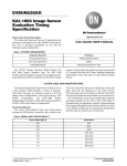
1
APPLICATION NOTE
TDA8787A
INTERFACE FRONT END BOARD CAMERA
CAMDEMO 87A
AN 00012
Philips Semiconductors
TDA8787A
Interface Front End Board for Camera Camdemo 87A
Application Note
AN 00012
Summary
This application note describes on the one hand how to use the TDA8787A.
On the other hand, an example of application is given using an Interface Front End (IFE)
board performed with a TDA8787A , a ¼ “ medium resolution Sharp CCD sensor and its
companion circuits.
The front-end board has been developed in such a way that it can be easily connected to an
evaluation board of the Philips DSP family.
Associated with its sister DSP board built around the SAA8112, this IFE board gives an
example of basic video camera application.
All rights are reserved. Reproduction in whole or in part is prohibited without the prior consent of the copyright owner.
The information presented in this document does not form part of any quotation or contract, is believed to be accurate and
reliable and may be changed without notice. No liability will be accepted by the publisher for any consequence of its use.
Publication thereof does not convey nor imply any license under patent - or other industrial or intellectual property rights.
-2-
Philips Semiconductors
TDA8787A
Interface Front End Board Camera Camdemo 87A
APPLICATION NOTE
TDA8787A
INTERFACE FRONT END BOARD CAMERA
CAMDEMO 8787A
Author(s):
Dominique LOYER
S&A - Caen
France
PRELIMINARY
Keywords:
Imaging
Camera
Front end
TDA8787A
CCD Signal processor
Date : February 2000
-3-
Application Note
AN 00012
Philips Semiconductors
TDA8787A
Interface Front End Board Camera Camdemo 87A
Application Note
AN 00012
CONTENTS
1
IC Front end TDA8787A description _______________________________________5
1.1 General Description ________________________________________________________ 5
1.2 Timing diagram____________________________________________________________ 7
1.3 Theory of operation ________________________________________________________ 9
1.3.1
1.3.2
1.3.3
1.3.4
1.3.5
1.3.6
Correlated Double Sampling (CDS) _______________________________________________9
Programmable Gain Amplifier __________________________________________________10
Input DC restoration or Input Bias Level Clamping__________________________________10
Black Level Clamping. ________________________________________________________11
Input Blanking. ______________________________________________________________11
OFDOUT function. ___________________________________________________________11
1.4 Serial interface____________________________________________________________ 12
1.5 Internal registers__________________________________________________________ 13
1.5.1
1.5.2
1.5.3
OFD function ________________________________________________________________13
PGA gain control_____________________________________________________________13
Control pulses polarity settings __________________________________________________14
2
Power and grounding recommendations ___________________________________15
3
Front end typical application_____________________________________________17
3.1 Interface connector pinning _________________________________________________ 19
3.2 Electrical diagrams ________________________________________________________ 21
3.3 Optical-mechanical block ___________________________________________________ 21
4
Enclosures ___________________________________________________________23
5
References ___________________________________________________________27
6
LIST of FIGURES_____________________________________________________28
-4-
Philips Semiconductors
TDA8787A
Interface Front End Board Camera Camdemo 87A
Application Note
AN 00012
1 IC FRONT END TDA8787A DESCRIPTION
1.1
General Description
The TDA8787A is a 3.3V, 10 bit analog-to-digital interface for CCD cameras.
TDA8787A is a low power, low supply voltage circuit which is able to operate from 2.7 volts
to 3.6 volts.
Analog and digital supplies have several separated pins VCCA, VCCD and VCCO. Therefore
special care must be taken when an application board is designed in order to avoid any external
disturbing effect when using a non correct filtering circuit around these VCC’s lines. See
Chapter 3.
All digital inputs, as Standby inputs (STBY) and Output Enable Not (OE(N)) are TTL logic
level compatible.
In addition, the outputs are CMOS level compatible. No adaptation circuits has been required
to interface output data with CMOS family circuit working under the same value voltage of
power battery.
Here is the list of the main functions implemented:
.
.
.
.
.
.
.
.
Correlated Double Sampling circuit ( CDS )
Programmable Gain Amplifier(PGA)
low power 10 bit Analog-to-Digital Converter
integrated reference voltage regulator
Serial Interface function for programming internal registers (SRI)
8 bit Digital-to-Analog Converter for extra external control function (OFD)
Blanking interface
Standby mode facilities
The TDA8787A has a 18 MHz maximum clock frequency.
-5-
Philips Semiconductors
Application Note
AN 00012
TDA8787A
Interface Front End Board Camera Camdemo 87A
Here is the CCD signal path:
CLPDM
BLK
Ref
IN
CDS
SHIFT
PGA
shifter
dac 7-bit
CLAMP
CLPOB
Figure 1. CCD signal path
-6-
ADC
Philips Semiconductors
Application Note
AN 00012
TDA8787A
Interface Front End Board Camera Camdemo 87A
1.2
Timing diagram
A typical input signal of CCD is depicted in Figure. 2, in comparison with SHP, SHD pulses,
the Sample & Hold control pulses.
The CCD signal can be divided into three main parts, the reset gate pulse, the reset hold level
(floating gate or black level) and the actual video level.
Figure 2. Typical CCD signal
Reset
Black
level
CCD
signal
Input IN
N
Video
Th(SHP)
SHP
N
Th(SHD)
SHD
N
CLK
Thold
11ns
Data out
N-3
N-2
-7-
N-1
N
Philips Semiconductors
TDA8787A
Interface Front End Board Camera Camdemo 87A
Application Note
AN 00012
Inside the TDA8787A, there is a pipeline delay between the external SHP and SHD signals
present at the inputs and the actual internal switch action which samples the CCD signal. This
delay is lower than 2 ns.
This delay has to be taken into account during the definition of an application diagram to make
sure the video signal is correctly processed and no overlap exists between the different
sampled periods (black and active video) and SHP, SHD control pulses.
-8-
Philips Semiconductors
TDA8787A
Interface Front End Board Camera Camdemo 87A
1.3
Application Note
AN 00012
Theory of operation
1.3.1 Correlated Double Sampling (CDS)
Figure 3. shows the simplify block diagram of the TDA8787A’s CDS.
The CDS is required in CCD systems as a mean for removing several types of noises. With
video information, reset noise, thermal noise, 1/f noise generated are present at the CCD
output signal.
Since part of low frequencies noises are assumed to be correlated both during the active part
of the video and during the feed through, major part of this noise can be cancelled by
subtracting the feed through level from the video.
This classical technique known as Doubled Correlated Sampling uses SHP and SHD pulses to
control the internal process of CDS. The timings of the operation is describe in the Fig 3&4 in
the TDA8787A’s Data Sheet.
During SHP period, the sample & hold goes into the hold mode, taking a sample of the reset
level (floating gate level) including the noise. At time SHD, the second sample & hold takes a
sample of the video level.
At the end, the result of this operation in the CDS is the generation of new signal which is now
the true useful video level: Vreset – Vvideo. Then, this video level will be presented at the
input of the digitally programmable gain amplifier tied down by DSP.
The TDA8787A actually uses two CDS circuits in a “ping pong” way. This method reduces
the bandwidth per stage as compared to a single channel CDS. Thus, the output from one of
the two CDS is valid for an entire clock cycle.
A and B are often named odd and even pixels.
IN
SHP.A
A
SHD.A
A
SHP.B
B
SHD.B
B
to PGA
Figure 3. CDS block diagram
-9-
Philips Semiconductors
Application Note
AN 00012
TDA8787A
Interface Front End Board Camera Camdemo 87A
1.3.2 Programmable Gain Amplifier
The active video level varies according to the illumination of the scene observed.
In order to ensure that the maximum of the useful dynamic range of the ADC is used even
under low light conditions, the video signal is amplified, using this programmable gain
amplifier loop (PGA). The gain range is 0dB—36dB.
The amount of gain is adjusted by settings resulting of computation in the DSP and transmitted
back to the TDA8787A amplifier by the 3 wires serial interface.
1.3.3 Input DC restoration or Input Bias Level Clamping
The Figure 3 shows the input stage in a common application. The buffered video signal passes
through the external coupling capacitor Cin. To restore the DC level to the desired baseline, a
clamping circuit is used during the “dummy clamp” period (CLPDM = Low). In all
applications, we advice to enable this loop all the time.
CLPDM
vcc
Ref
CCD
CDS
SHIFT
PGA
Cin
CLAMP
CLPOB
Figure 4. Input Clamp - DC Restoration
-10-
Philips Semiconductors
TDA8787A
Interface Front End Board Camera Camdemo 87A
Application Note
AN 00012
1.3.4 Black Level Clamping.
For a good signal processing, the video signal must be referenced to a well established
“floating gate level” or “black level”. For this operation, the common way is to used the
CCD’s optical black (OB) pixels, usually at the beginning of the CCD lines, as a calibration
level. It is strongly recommended to reserve at least 12 black pixels. During this period,
CLPOB active, the black level clamping measures the difference between the input level and
the desired reference level. This reference level is programmed by the Serial Interface to set the
desired “black color”. Of course, this black level offset is applied to both ways of the “ping
pong” CDS.
This reference level is hold in the capacitors CPCDS1&2. The calculation of these capacitors is
fully dependent of the maximum ripple voltage acceptable and the pixel frequency. The next
formula can be used to calculate them:
CPCDS min =
I Max _ load ∗ t load
Vripple
with I Max _ load = 350 µA at PGA code = 0 and I Max _ load = 10 µA at
PGA code = 383;
1.3.5 Input Blanking.
In many applications, the IFE is exposed to large input signals, mainly during the “blanking
period” and in “ CCD shutter high speed” mode. To avoid problems with data processing, the
TDA8787A includes a blanking function.
When PBK is active, the digital outputs go to the desired clamp reference level.
1.3.6 OFDOUT function.
To control the substrate bias level of some CCD’s, in order to cancelled the smear effect, the
TDA8787A provides a voltage control output. This analog output is controlled via the Serial
Interface by a 8-bit Digital-to-Analog Converter. The desired value is usually set during the
calibration of the camera.
-11-
Philips Semiconductors
TDA8787A
Interface Front End Board Camera Camdemo 87A
1.4
Application Note
AN 00012
Serial interface
Communication with the configuration register is done through a Serial Interface (SRI).
Just after the “power on” action, a message must be transmitted via the serial interface to the
TDA8787A internal registers to set a correct working configuration.
Maximum frequency: 5MHz.
A writing sequence of a serial message is made of 10 data bit + 2 address bit.
A1,A0, SD9,SD8,…,SD2,SD1; with A1 bit first sent.
VSYNC signal can be used to synchronize the registers writing with the Vertical Drive (VD)
signal in order to set all the parameters only after a complete image has been displayed. The
polarity settings are excluded from the VSYNC latch.
In some applications, this signal can be linked to SEN signal when the firmware takes account
of VD.
The setup and hold times, are described in the TDA8787A Data Sheet.
Example:
SDATA
A1
A0 sd9 sd8 sd7 sd6 sd5 sd4 sd3 sd2 sd1 sd0
SCLK
SEN
VSYNC
OR
VSYNC
-12-
Philips Semiconductors
Application Note
AN 00012
TDA8787A
Interface Front End Board Camera Camdemo 87A
1.5
Internal registers
The configuration register is programmed to set the requested conditions :
- PGA gain control;
- OFD output control;
- ADC clamp reference control (be careful SD7, SD8 and SD9 must be set to 0;
- Controls pulse polarity settings for SHP, SHD ,CLAMP’s, PBK and CLK.
Timing and polarity settings of all these signals, (active edge or level) are given in details in
TDA8787A specification and can be summarized in the following tables.
1.5.1 OFD function
Serial address A1A0= 01
Dec
0
255
hex
00
ff
Typical Value of OFD out
0.0V
1.0 V
1.5.2 PGA gain control
Serial address A1A0 = 00. SD9 = 0
Hex
000
040
080
0C0
100
13F
180
4.5dB
+Gain
0 dB
6 dB
12 dB
18 dB
24 dB
30 dB
36 dB
Bit 8
SD8
0
0
0
0
1
1
1
Bit 7
SD7
0
0
1
1
0
0
1
Bit 6
SD6
0
1
0
1
0
0
0
Bit 5
SD5
0
0
0
0
0
1
0
Bit 4
SD4
0
0
0
0
0
1
0
-13-
Bit 3
SD3
0
0
0
0
0
1
0
Bit 2
SD2
0
0
0
0
0
1
0
Bit 1
SD1
0
0
0
0
0
1
0
Bit 0
SD0
0
0
0
0
0
1
0
dec
0
64
128
192
256
319
383
Philips Semiconductors
TDA8787A
Interface Front End Board Camera Camdemo 87A
Application Note
AN 00012
1.5.3 Control pulses polarity settings
Serial address A1A0 = 11
SD0 =1
SD1=1
SD2=0
SD3=1
SD4 not used
SD5=1
SD6=0
SHP, SHD active level HIGH
CLK active edge RISING
CLPDM always active level LOW
CLPOB active level HIGH
PBK active level HIGH
VSYNC active edge RISING
-14-
Philips Semiconductors
TDA8787A
Interface Front End Board Camera Camdemo 87A
2
Application Note
AN 00012
POWER AND GROUNDING RECOMMENDATIONS
When designing a printed circuit board for application such as PC camera, surveillance
cameras, camcorders and digital still cameras, care should be taken to minimize the noise.
For the front end integrated circuit, the basic rules of printed circuit board design and
implementation of analog components (such as classical operational amplifiers) must be
respected, particularly for power and ground connections.
Firstly, in all cases, we recommend to link the following pins on the same good ground:
CPCDS1 CPCDS2
c
c
DCPLC
c
AGND
Ground
The following additional recommendation is given for the CDS input pins which are internally
connected to the programmable gain amplifier.
Secondly, the connections between the CCD, the CCD transistor interface and the CDS input
should be as short as possible and a ground ring protection around these connections can be
beneficial for noise performances.
To separate analog and digital supplies provides the best solution. If it is not possible to do this
on the board, then the analog supply pins must be de-coupled effectively from the digital
supply pins.
If the same power supply and ground are used for all pins the de-coupling capacitors must be
placed as close as possible to the IC package.
In a two-ground system, in order to minimize the noise through package and die parasitic, the
following recommendations must be implemented:
All the analog and digital supply pins must be well de-coupled to the analog ground plane.
Only the ground pins associated to the digital outputs must be de-coupled to the digital ground
plane. The analog and digital ground planes must be connected together at one point close to
the ground pin associated with the digital outputs.
The digital output pins and their associated lines should be shield by the digital ground plane
which can be used then as return path for digital signal.
-15-
Philips Semiconductors
Application Note
AN 00012
TDA8787A
Interface Front End Board Camera Camdemo 87A
Never use a digital ground plane under analog wires and analog ground plane under digital
connections.
ID
L
VCC
IA
Power
supply
L
VCC
TDA8787A
ia
Analogue
Digital
C
id
C
IA+ia
Agnd
Bounding resistor
ID+id
Dgnd
Ground plane
Figure 5. Grounding connections
On the printed board area loop of supply current and impedance of different ground
connections must be minimized, the de-coupling capacitors C (ceramic capacitor) must be
placed as close as possible to the VCCA and VCCD pins.
Series inductors in power supply lines may be used to improve de-coupling
( E.g. 1…5 µh or BLM components ).
Using above de-coupling scheme, both analog and digital supplies can be connected together
to a single stable 5 volt supply.
-16-
Philips Semiconductors
TDA8787A
Interface Front End Board Camera Camdemo 87A
Application Note
AN 00012
3 FRONT END TYPICAL APPLICATION
The front end IC TDA8787A, used with one SAA 81XX of DSP Philips IC’s family, is the
core of a high quality video application.
Image sensor, vertical driver, timing generator, micro controller, memories, and DC-DC
converter, are the others functions to build a modern CCD video camera
A camdemo is made of two different boards:
-
An interface front end also called IFE board.
A digital processing board.
The whole camera is then made up with the following integrated circuits:
-
CCD sensor LZ 2413 for standard NTSC LZ2423 for PAL standard
Vertical Driver (VD) LR36683
Pulse Pattern Generator (PPG) LZ95G55
Front End for analog processing and digitalization TDA8787A (FE)
Digital Signal Processing and formatting ( DSP) SAA8112
Video encoder SAA7102
Memory EEPROM PCD8594
In addition on the IFE schematic, we find:
-
2 simple small SMPS stages to transform the 5 volts power battery voltage into +15Volts
and -8Volts needed to bias the CCD and Vertical Driver devices.
One transistor buffer stage to interface the CCD with the FE;
One non inverting amplifier stage to translate the OFDOUT signal of the FE to the FD
input of the CCD;
One push pull stage to transform the OFDX signal of the PPG into a high voltage pulse
command added to the OFD on the FD CCD input (shutter function).
These boards are connected together by a connector in order to be able to mix different
configurations of our circuits ( TDA8784+SAA8112 or TDA8787A+SAA8112 …).
In a previous application note, AN97037, evaluation board for camera more details can be
found about the description of this concept.
This present application has been modified in the front-end part only to become compatible
with the TDA8787A circuit.
-17-
Philips Semiconductors
TDA8787A
Interface Front End Board Camera Camdemo 87A
Application Note
AN 00012
For people non-familiar with the DSP SAA81xx IC’s family, it is recommended to read this
previous document to get better understanding of the DSP SAA8112 performance.
If there is no basic change for the system point of view due to the substitution of the TDA8784
by TDA8787A, the use of new TDA 8787A circuit improves the global performance of the
basic application: more simple connection with the PPG, lower noise, possible choice of the
pulse polarity by software, lower power consumption and less external components.
-18-
Philips Semiconductors
TDA8787A
Interface Front End Board Camera Camdemo 87A
3.1
Application Note
AN 00012
Interface connector pinning
In the description list below and in the IFE diagram:
-
DS
UC
EE
JB
JD
=
=
=
=
=
DSP SAA8112
micro-controller implemented in the SAA8112
Eeprom
I2C / UART connector
digital output connector
Names on connector
1
3
5
7
9
11
13
15
17
19
21
23
25
27
29
31
33
35
37
39
41
43
+5 V
GND
UC5 P1-3
UC2 P1 –0
CLK2
UC7 P1-5 PAL/NTSC
UC29 P2-5
UC28 P2-4
UC27 P2-3
UC26 P2-2
P1 INPUT
P0 INPUT
DATA 8
DATA 6
DATA 5
DATA 3
DATA 1
SCLK INPUT
SDATA INPUT
STAND BY TDA
GND
+5V
2
4
6
8
10
12
14
16
18
20
22
24
26
28
30
32
34
36
38
40
42
44
-19-
+5 V
GND
UC4 P1-2
CLK1
VD UC14 P3-2
HD UC16 P3-4
FI UC18 P3-6
GND
+5 V n.u.
UC25 P2-1
SMPS
DATA 9
DATA 7
+5V n.u.
GND
DATA 4
DATA 2
DATA 0
SEN
DACOUT
GND
5 +V
Philips Semiconductors
TDA8787A
Interface Front End Board Camera Camdemo 87A
Names on micro-controller
BIT
P0.0
P0.1
NAME
SCLE
SDAE
DESCRIPTION
I2C bus clock for EEPROM
I2C bus data for EEPROM
P1.3
*P1.5
P1.6
P1.7
PPR_OEN
TVMD
SCLM
SDAM
TDA8787A Output Enable Not
PPG mode select
I2C bus clock for MMI
I2C bus data for MMI
P2.0
P2.1
P2.2
P2.3
P2.4
P2.6
PP_STDBY
ACLXP
EEUD
EENR
SMD1
POR
TDA8787A standby pin
PPG internal reset (all clear)
PPG Electric Exposure 2
PPG Electric Exposure 3
PPG Shutter control 1
POR for DSP
P3.0
P3.1
P3.2
*P3.6
P3.7
SNDA
SNCL
VD
FI
SNRST
SNERT bus data for DSP
SNERT bus clock for DSP
VD interrupt input
PPG Field Index
SNERT bus reset for DSP
-20-
Application Note
AN 00012
Philips Semiconductors
TDA8787A
Interface Front End Board Camera Camdemo 87A
3.2
Application Note
AN 00012
Electrical diagrams
Reported in enclosures.
3.3
Optical-mechanical block
In the front of the TDA8787A there is a CCD sharp LZ2413 which is a ¼ type solid state
image sensor having 542*498 pixels. This CCD is compatible with the NTSC standard. For a
PAL application this CCD can be changed and directly replaced by the LZ2423 CCD type but
in this case the quartz oscillator must be also changed:
-
19.06993 MHz is used for NTSC standard;
19.3125 MHz is used for PAL standard;
In the same time, the declaration of NTSC or PAL standards must be swapped in the setting of
the DSP program and all parameters concerning the active and black windows pixels must be
updated. It can be done with the Graphic User Interface (GUI) developed in our US
laboratory, to demonstrated the SAA8112 possibilities (Reference N°2).
In the front of the CCD, there is a optical low pass filter from American KSS, Inc.
This particular filter is currently being produced by this manufacturer under the reference
OG-BF389 (3122 168 7514.0), the size of this infrared filter is 7.75*7.25*3.27 mm and must
be introduced in the optical block as shown below.
Light from lens
To CCD
Figure 6. Optical filter
-21-
Philips Semiconductors
TDA8787A
Interface Front End Board Camera Camdemo 87A
Application Note
AN 00012
In addition each kit is containing the following elements:
-
1 piece CS mount interface
1 piece under-plate
1 piece CS mount ring
1 piece retaining ring
1 piece filter foan
2 screws M2.5.
The IFE kit can be delivered with CS CCTV lens coming from different suppliers.
Lens which generally are 4mm F 1.2 or 8 mm F1.2 depending available material in stock.
Documentation on these elements are available on request.
-22-
Philips Semiconductors
TDA8787A
Interface Front End Board Camera Camdemo 87A
4 ENCLOSURES
-23-
Application Note
AN 00012
Philips Semiconductors
TDA8787A
Interface Front End Board Camera Camdemo 87A
-24-
Application Note
AN 00012
Philips Semiconductors
TDA8787A
Interface Front End Board Camera Camdemo 87A
Application Note
AN 00012
Figure 7. Electrical schematic
Figure 8. Components implementation upper side
-25-
Philips Semiconductors
TDA8787A
Interface Front End Board Camera Camdemo 87A
Application Note
AN 00012
Figure 9. components implementation lower side
-26-
Philips Semiconductors
TDA8787A
Interface Front End Board Camera Camdemo 87A
5 REFERENCES
1) Application Note AN97037 – May 1992
Camera evaluation board documentation SDA8112-TDA8786
Author: Stephane Desproges
2) Addendum to AN97037 – June 1997
Camera I’C controller software documentation and user manual
Author: Jürgen Krehnke
3) Caen Team Design – Internal Note
Authors: S. Jacquet, R. Morisson
4) Software for TDA8787A, version V3.12
(Modification of V3.11 for TDA8786 by C. Kohler and H. Jacquemin) .
-27-
Application Note
AN 00012
Philips Semiconductors
TDA8787A
Interface Front End Board Camera Camdemo 87A
Application Note
AN 00012
6 LIST OF FIGURES
Figure 1. CCD signal path __________________________________________________________________6
Figure 2. Typical CCD signal________________________________________________________________7
Figure 3. CDS block diagram ________________________________________________________________9
Figure 4. Input Clamp - DC Restoration ______________________________________________________10
Figure 5. Grounding connections ____________________________________________________________16
Figure 6. Optical filter ____________________________________________________________________21
Figure 7. Electrical schematic ______________________________________________________________25
Figure 8. Components implementation upper side _______________________________________________25
Figure 9. components implementation lower side _______________________________________________26
-28-