1
EVBUM2268/D
KAI-1003 Image Sensor
Evaluation Timing
Specification
http://onsemi.com
Altera Code Version Description
The Altera code (Firmware Version 1.1) described in this
document is intended for use in the AD9945 Timing Board.
The code is developed specifically for use with the
following system configuration:
EVAL BOARD USER’S MANUAL
Table 1. SYSTEM CONFIGURATION
Evaluation Board Kit
PN 4Hxxxx
Timing Generator Board
3F5592 (AD9945 20 MHz)
KAI−1003 Imager Board
3E8214
Framegrabber Board
National Instruments PCI−1424
sensors. It also provides the signals necessary for operation
of 2 Analog Front-End (AFE) chips, enabling independent
optimization of the AFE chips for dual channel readout
devices.
The 3F5592 Timing Generator Board features the
KSC−1000 Timing Generator chip. The KSC−1000
provides all of the signals necessary for an imaging system
using Full Frame (KAF) or Interline (KAI) family of image
ALTERA CODE FEATURES/FUNCTIONS
The Altera Programmable Logic Device (PLD) serves as
a state machine, which performs a variety of functions.
Three basic functions are required, common to all CCD
image sensor configurations: serial input steering, AFE
default
programming,
and
KSC−1000
default
programming. In addition, certain other functions specific to
the KAI−1003 Image Sensor is implemented.
PLD. The Altera PLD decodes the addressing of the serial
input, and steers the datastream to the correct device.
The serial input must be formatted so that the Altera PLD
can correctly decode and steer the data to the correct device.
The serial interface can be used to dynamically change the
operating conditions of the AFE or KSC−1000 chips by
reprogramming the appropriate registers. Reprogramming
these registers through the serial interface will have no effect
on the default settings that are automatically programmed
into these devices on power-up or board reset.
Serial Input Steering
The 3-wire serial interface enters the Timing Board
through the DIO Interface connector, and is routed to the
Table 2. SERIAL INPUT DEVICE SELECT
Device Select DS[2..0]
Serial Device
000
PLD
001
AFE1
010
AFE2
011
KSC−1000
100
(Not Used)
101
(Not Used)
110
(Not Used)
111
(Not Used)
© Semiconductor Components Industries, LLC, 2014
October, 2014 − Rev. 2
1
Publication Order Number:
EVBUM2268/D
…
Dn
DS2
DS1
DS0
R/W
A0
A1
A2
A3 (or Test)
D0
D1
D2
D3
D4
EVBUM2268/D
SLOAD_INPUT
SLOAD_xxx
SDATA_INPUT
SCLK_INPUT
ÏÏÏÏÏÏÏÏÏÏÏÏÏÏÏ
ÏÏÏÏÏÏÏÏÏÏÏÏÏÏÏ
(decoded PLD output)
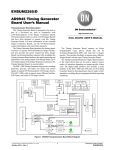
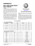
Figure 1. Serial Input Timing
The remaining bits in the bitstream are Data bits, LSB
first, with as many bits as are required to fill the appropriate
register.
The first 3 bits in the datastream are the Device Select bits
DS[2..0], sent MSB first, as shown in Figure 1. The Device
Select bits are decoded as shown in Table 2.
The next bit in the datastream is the Read/Write bit (R/W).
Only writing is supported; therefore this bit is always LOW.
The definition of next four bits in the datastream depends
on the device being addressed with the Device Select bits.
For the KSC−1000 device, they are Register address bits
A[0..3], LSB first. For the AD9945 AFE, they are Register
Address bits A[0..2], LSB first, followed by a Test bit which
is always set LOW.
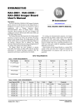
AFE Default Initialization
A0
A1
A2
Test
D0
D1
D2
D3
D4
D5
D6
D7
D8
D9
D10
D11
Upon power up, or when the BOARD_RESET button is
pressed, the PLD programs the registers of the two AFE
chips on the Timing Generator Board to their default settings
via the 3-wire serial interface. See Table 9 for details.
The AD9945 AFE must be reprogrammed on power-up, as
it does not retain register settings when power is removed.
SLOAD_AFE_x
SDATA
SCLK
ÏÏÏÏÏÏÏ ÏÏÏÏÏÏÏ
ÏÏÏÏÏÏÏ ÏÏÏÏÏÏÏ
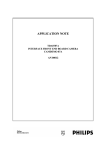
Figure 2. AFE Initialization Timing
inputs SW[4..1] and DIO[15..0] (See Table 10 through
Table 25 for details). The KSC−1000 must be
reprogrammed on power-up, as it does not retain register
settings when power is removed.
The KSC−1000 default settings automatically
programmed by the PLD allow the Evaluation Board Kit
user to operate the CCD image sensor with minimal
intervention and no programming. The default settings are
chosen to comply with the appropriate CCD device
specifications (See References). The registers, line tables
and frame tables described in this document also serve as
examples for those who wish to create their own KSC−1000
timing.
The data for each AFE register is formatted into two bytes
of data, as shown in Figure 2. The Test bit is always low, and
the Address bits specify the register being programmed, as
shown in Table 9. Each byte is read into an 8-bit shift
register, and is shifted out as a serial stream of eight bits.
Each register in the AFE is programmed in this fashion until
the entire AFE is programmed.
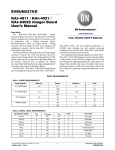
KSC−1000 Default Initialization
Upon power-up, or when the BOARD_RESET button is
pressed, the Altera PLD programs the registers of the
KSC−1000 chip on the AFE Timing Generator Board to
their default settings via the 3-wire serial interface.
The default settings are selected by the user through the PLD
http://onsemi.com
2
SDATA
…
Dn
ÏÏ
Ï
ÏÏ
ÏÏÏÏ
Ï
ÏÏÏÏ
Ï
ÏÏÏÏÏÏÏ ÏÏÏÏÏÏÏ
ÏÏÏÏÏÏÏ ÏÏÏÏÏÏÏ
R/W
A0
A1
A2
A3
D0
D1
D2
SLOAD_TG
[Dummy Bits]
EVBUM2268/D
SCLK
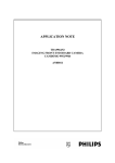
Figure 3. KSC−1000 Initialization Timing
The data for each KSC−1000 register is formatted into
bytes of data, as shown in Figure 3. The Read/Write bit is
always low, and the Address bits specify the register being
programmed, as shown in Table 3. Each byte is read into an
8-bit shift register, and is shifted out of the PLD as a serial
stream of eight bits. The last byte of data sent to a particular
register may need to be padded with extra “dummy” bits;
the SLOAD_TG signal is brought HIGH at the appropriate
time so that the correct number of bits are streamed into each
register, and the extra bits are ignored. Each register in the
KSC−1000 is programmed in this fashion until the entire
device is programmed.
Table 3. KSC−1000 REGISTERS
Register Address
Register Description
Data Bits
0
Frame Table Pointer
3
1
General Setup
202
2
General Control
2
3
INTG_STRT Setup
30
4
INTG_STRT Line
13
5
Signal Polarity
25
6
Offset
78
7
Width
65
8
Frame Table Access
(Variable)
9
Line Table Access
(Variable)
PLD State Machine
the timing sequences to change the Electronic Shutter
position, for example.
The Altera PLD contains a State Machine that parallels
the operation of the KSC−1000. The PLD controls the
KSC−1000 through the VD_TG output, and monitors
several of the KSC−1000 outputs, enabling it to track and
control the operation of the Timing Generator.
Integration Clock
The Altera PLD uses the System Clock and an internal
counter to generate a 1.0 ms-period clock. This clock is used
to generate an internal delay after power-up or Board Reset.
It may also be used to control precise integration times for
the image sensor.
Remote Board Reset
The DIO14 input is used as a remote Board Reset control
line. The Altera PLD monitors this input, and when DIO14
goes HIGH, the ARSTZ (active low) output to the
KSC−1000 is asserted, disabling and clearing the timing
generator. When DIO14 goes LOW, the ARSTZ output is
de-asserted, and the Power-up/Board Reset initialization
sequence is executed. This allows programmable control of
Output Channel Control
PLD input SW1 is used to select one of the supported
operation modes: Full Field Single Output, or Interlaced
Dual Output. When making a change to the switch settings,
the user must initiate a Board Reset for the change to take
http://onsemi.com
3
EVBUM2268/D
Binning Control
effect, either by pressing the BOARD_RESET button (S1)
on the Timing Board, or by setting and resetting the Remote
Reset (DIO14) input.
PLD input SW3 is used to select between 2×2 Binning
Single Output, and normal operation (no binning). When
making a change to the switch settings, the user must initiate
a Board Reset for the change to take effect, either by pressing
the BOARD_RESET button (S1) on the Timing Board, or
by setting and resetting the Remote Reset (DIO14) input.
Dual channel output with binning is not supported in the
board firmware. Therefore, if both SW1 and SW3 are high,
the result will be single channel binning mode (i.e. binning
will override 2 channel mode).
Integration & Electronic Shutter Control
The PLD inputs DIO[11..7] may be used to select the
integration time. See Table 14 for timing details for each
operating mode. In general, when making a change to the
DIO[11..7] settings, the user must initiate a Board Reset for
the change to take effect, either by pressing the
BOARD_RESET button (S1) on the Timing Board, or by
setting and resetting the Remote Reset (DIO14) input.
ALTERA CODE I/O
Inputs
and various outputs from the KSC−1000 Timing Generator.
The KSC−1000 outputs are monitored by the PLD to control
auxiliary timing functions, and keep the KSC−1000 and
Altera PLD synchronized. The remote digital inputs
DIO[15..0] are optional, and are not required for KAI−1003
operation, but may be used to control integration time.
The Altera PLD has multiple inputs that may be used to
control certain functions. The inputs include: user selectable
switches SW[4..1] on the Timing Board; remote digital
inputs DIO[15..0] and a 3-wire serial interface through
Timing Board connector TP6; Timing Board signals;
Table 4. ALTERA INPUTS
Symbol
Location
Description
BOARD_RESET
S1 (Board Reset)
The Rising Edge of this Signal Clears and Re-initializes the PLD
SYSTEM_CLK
U5
40 MHz Clock, 2X the Desired Pixel Clock Rate
PIXCLK_TG
−
20 MHz Pixel Rate Clock from the KSC1000TG (Not Used)
JMP1
S2−1
HIGH = Dual Output; LOW = Single Output, Full Image
JMP2
S2−2
(Not Used for KAI−1003 Operation)
JMP3
S2−3
Binning Mode: HIGH = 2 × 2 Binning, Single Output; LOW = No Binning
JMP4
S2−4
(Not Used for KAI−1003 Operation)
DIO[6..0]
J3
(Not Used for KAI−1003 Operation)
DIO[11..7]
J3
Integration Control See Table 14
DIO[13..12]
J3
(Not Used for KAI−1003 Operation)
DIO14
J3
Remote Board Reset
(HIGH activates ARSTZ; Falling Edge Activates BOARD_RESET)
DIO15
J3
(Not Used for KAI−1003 Operation)
SLOAD_INPUT
TP6−2
3-wire Serial Interface LOAD Signal Input
SCLOCK_INPUT
TP6−3
3-wire Serial Interface CLOCK Signal Input
SDATA_INPUT
TP6−4
3-wire Serial Interface DATA Signal Input
EXT CLK INPUT
J11
(Not Used for KAI−1003 Operation; Not Populated)
Hx_TG
−
Pixel Rate Clock Inputs (from KSC−1000)
Vx_TG
−
Line Rate Clock Inputs (from KSC−1000)
RG_TG
−
Reset Clock Input (from KSC−1000)
SHx_TG
AFE Clamp and Sample Signal Inputs (from KSC−1000)
DATACLKx_TG
−
Data Clock Inputs (from KSC−1000)
PIXCLK_TG
P1−3
Pixel Valid Input (from KSC−1000)
LINE_VALID_TG
P1−2
Line Valid Input (from KSC−1000)
FRAME_VALID_TG
P1−1
Frame Valid Input (from KSC−1000)
http://onsemi.com
4
EVBUM2268/D
Table 4. ALTERA INPUTS (continued)
Symbol
Location
Description
CLPDM_TG
−
Black Clamping Signal Inputs (from KSC−1000)
CLPOB_TG
−
Black Clamping Signal Inputs (from KSC−1000)
PBLK_TG
Pixel Blanking Signal Inputs (from KSC−1000)
AMP_EN_TG
−
Amplifier Enable Input (from KSC−1000)
INT_START_TG
−
Integration Start Signal Input (from KSC−1000)
Outputs
INTEGRATE signal used for external monitoring and
synchronization; the PLD internally generated 1 ms
Integration Clock.
The Altera PLD outputs include: the 3-wire serial
interface; control signals to and from the KSC−1000; the
Table 5. ALTERA OUTPUTS
Symbol
Location
Description
PIX_VALID
P1−1
Used to Monitor KSC−1000 Pixel Clock
LINE_VALID
P1−2
Used to Monitor KSC−1000 Line Valid
FRAME_VALID
P1−3
Used to Monitor KSC−1000 Frame Valid
INTEGRATE_CLK
TP5
1 ms Integration Clock Output
INTEGRATE
J6
High During CCD Integration Time
VD_TG
TP7
Control Signal to KSC−1000
HD_TG
−
(Not Used for KAI−1003 Operation)
ARSTZ_TG
−
KSC−1000 Force-Reset Signal
AFE_CLK_PLD
TP13
AD9945 Analog-to-Digital Conversion Clock signal
SHPx_PLD
TP14, TP18
AD9945 CDS Sampling CCD Reference Clock Signal
SPDx_PLD
TP15, TP17
AD9945 CDS Sampling CCD Data Clock Signal
CLPDM_PLD
CLPOB_PLD
PBLK_PLD
−
AD9945 Clamping Control Signals
HD_AFE_x, VD_AFE_x
−
(Not Used for KAI−1003 Operation)
SLOAD_TG
TP9
KSC−1000 SLOAD
SLOAD_AFEx
TP12, TP24
AD9945 AFE SLOAD
SCLOCK
TP27
3-wire Serial Interface CLOCK Signal Output
SDATA
TP28
3-wire Serial Interface DATA Signal Output
SDAT, SCLK
TP30, TP31
(Not Used for KAI−1003 Operation)
SLOAD_DAC
TP29
(Not Used for KAI−1003 Operation)
SLOAD_LED_DAC
TP11
(Not Used for KAI−1003 Operation)
IMAGER_PWR_ENA
−
(Not Used for KAI−1003 Operation)
SYSTEM_CLK_TG
−
(Not Used for KAI−1003 Operation)
PLD_OUT[19..0]
J5
Timing Signals to Imager Board
SYSTEM_CLOCK_OUT
−
(Not Used for KAI−1003 Operation)
http://onsemi.com
5
EVBUM2268/D
KAI−1003 TIMING CONDITIONS
System Timing Conditions
Table 6. SYSTEM TIMING
Description
Symbol
Time
Notes
System Clock Period
Tsys
25 ns
40 MHz System Clock
Unit Integration Time
Uint
1.0 ms
Generated by PLD
Power Stable Delay
Tpwr
125 ms
Typical
Default Serial Load Time
Tsload
1.2 ms
Integration Time
Tint
Typical
Operating Mode Dependent
CCD Timing Conditions
Table 7. CCD TIMING
Description
Symbol
Time
Pixel
Counts
Notes
H1, H2, RESET Period
Tpix
50.0 ns
1
20 MHz Clocking of H1, H1L, H2, RESET
VCCD Delay
TVd
50.0 ns
1
Delay after Hclks Stop
VCCD Transfer Time
TV
2.0 ms
40
V2 Rising Edge to V2 Falling Edge
HCCD Delay
THd
1.5 ms
30
Delay before Hclks Resume
Vertical Transfer Period
Vperiod
3.55 ms
71
Vperiod = TVd + TV + THd
Horizontal Pixels
HPIX
56.0 ms
1120
1060 CCD Pixels + 60 Overclock Pixels
Vertical Pixels
VPIX
1056
1032 CCD Lines + 21 Overclock Lines
Line Transfer Time
TL
9.55 ms
1191
TL = Vperiod + HPIX
Photodiode Transfer Time
TVh
18 ms
360
V2 3rd Level
Photodiode Delay
Trd
40 ms
800
Delay before Vclks Begin
Shutter Pulse Setup
Tset
1.5 ms
30
Delay after Hclks and Vclks Stop
Shutter Pulse Time
Tes
7.5 ms
150
Shutter Pulse Width
Shutter Pulse Delay
Thves
1 ms
20
Delay before Hclks and Vclks Resume
Symbol
Time
Pixel
Counts
Notes
PCI−1424 Timing Conditions
Table 8. PCI−1424 TIMING
Description
PIX Period
TPIX
50.0 ns
1
20 MHz Clocking of DATACLK Sync Signal
FRAME Time
TFRAME
59.1 ms
1182791
TFRAME = TPIX * ((Vperiod + HPIX) * VPIX)
http://onsemi.com
6
EVBUM2268/D
MODES OF OPERATION
When changing the integration time, the user must initiate
a Board Reset for the change to take effect, either by pressing
the BOARD_RESET button (S1) on the Timing Board, or
by setting and resetting the Remote Reset (DIO14) input.
The following modes of operation are available to the
user:
Electronic Shutter Modes
The Evaluation Board electronic shutter circuitry
provides a method of precisely controlling the image
exposure time without any mechanical components. Charge
may be cleared from the CCD photodiodes at some time
during the readout of the previous frame. This allows
integration times of less than one frame time, to compensate
for high light exposures that would otherwise saturate the
CCD.
The default integration time can be set from 1x to 1/8x
frame time via the digital inputs DIO[11..7]. See Table 14.
Black Clamp Mode
One of the features of the AD9945 AFE chip is an optical
black clamp. The black clamp (CLPOB) is asserted during
the CCD’s dark pixels and is used to remove residual offsets
in the signal chain, and to track low frequency variations in
the CCD’s black level. The location of these pulses is fixed
in the default KSC−1000 settings, but can be adjusted
dynamically through the 3-wire serial interface. The default
settings are shown in Table 11.
POWER-ON/BOARD RESET INITIALIZATION
background, the Altera PLD monitors the activity of the
KSC−1000, and the 3-wire Serial Interface.
When the board is powered up, the Board Reset button is
pressed, or the Remote Rest (DIO14) is toggled, the Altera
PLD is internally reset. When this occurs, state machines in
the PLD will first serially load the initial default values into
the AFE registers, then will load the KSC−1000 frame
tables, line tables, and registers.
Upon completion, the KSC−1000 will be ready to proceed
according to its programmed configuration. In the
AFE Register Default Settings
On power-up or board reset, the AFE registers are
programmed to the default levels shown in Table 9. See the
AD9945 specifications (References) for details of the AFE
registers.
Table 9. DEFAULT AD9945 AFE REGISTER PROGRAMMING
Register
Address
Description
Value
(decimal)
0
Operation
0
1
Control
0
2
Clamp
96
The Output of the AD9945 will be Clamped to Code 96 during the CLPOB Period
3
VGA Gain
20
Corresponds to a VGA Stage Gain of 6.0 dB
Notes
KSC−1000 Timing Generator Default Settings
Register 0: Frame Table Pointer
Register 0 contains the Frame Table Pointer, which
instructs the KSC−1000 to perform the timing sequence
defined in that table. Frame Table 0 is used for Single or
Dual Channel readout and Frame Table 1 is used for 2×2
Binning mode. The default setting depends on the position
of SW1 and SW3.
On power-up or board reset, The KSC−1000 is
programmed to the default settings as detailed in Table 10
through Table 25. See the KSC−1000 Device Specification
[1] for details of the KSC−1000 registers.
Table 10. REGISTER 0 DEFAULT SETTING
Register Entry
Data (Single or Dual Channel)
Data (Binning 2y2)
Frame Table Address
0
1
http://onsemi.com
7
EVBUM2268/D
Register 1: General Setup
The default settings written to Register 1 for the
KAI−1003 are the same for all 1-channel and binning
operating modes. Some values are different in 2-channel
mode. The entries for Register 1 are shown in Table 11.
Table 11. REGISTER 1 DEFAULT SETTING
Register Entry
Single Channel /Binning Data
Dual Channel Data
Pixels Per Line[0..12]
1120
560
Line Valid Pixel Start[0..12]
9
9
Line Valid Pixel Quadrature Start[0..1]
0
0
Line Valid Pixel End[0..12]
1119
559
CLPOB1_Pix_Start[0..12]
4
4
CLPOB1_Pix_End[0..12]
14
14
CLPOB2_Pix_Start[0..12]
6
6
CLPOB2_Pix_End[0..12]
1054
527
CLPDM1_Pix_Start[0..12]
0
0
CLPDM1_Pix_End[0..12]
0
0
CLPDM2_Pix_Start[0..12]
0
0
CLPDM2_Pix_End[0..12]
0
0
PBLK_Pix_Start[0..12]
1119
559
PBLK_Pix_End[0..12]
1
1
RG_Enable
1
1
H6_Enable
0
0
H4_Enable
1
1
H5_Enable
0
0
SH2_Enable
1
1
SH4_Enable
1
1
DATACLK1_Enable
1
1
DATACLK2_Enable
1
1
PIXCLK_Enable
1
1
H3_Enable
1
1
H1_Enable
1
1
H2_Enable
1
1
SH1_Enable
1
1
SH3_Enable
1
1
H6 24 mA Output Enable
0
0
H4 24 mA Output Enable
0
0
H5 24 mA Output Enable
0
0
RG 24 mA Output Enable
0
0
SH2 24 mA Output Enable
0
0
SH4 24 mA Output Enable
0
0
DATACLK1 24 mA Output Enable
0
0
DATACLK2 24 mA Output Enable
0
0
H3 24 mA Output Enable
0
0
H1 24 mA Output Enable
0
0
H2 24 mA Output Enable
0
0
SH1 24 mA Output Enable
0
0
SH3 24 mA Output Enable
0
0
DLL Frequency Range Select
8
8
http://onsemi.com
8
EVBUM2268/D
Register 2: General Control
Register 2 controls the Power Management and
Operation state of the KSC−1000. The Low Power Mode is
not used on the KAI−1003, so this bit is always LOW.
The Memory Table Mode bit is used to halt execution of the
KSC−1000 timing sequences and to enable programming of
the registers. The KSC−1000 Initialization sequence begins
with setting the Memory Table Mode bit in Register 2 to
Program Mode, and ends by setting the bit to Execution
Mode. See the KSC−1000 Device Specification
(References) for more details.
Table 12. REGISTER 2 SETTINGS
Register Entry
Program Mode
Execution Mode
Low Power Enable
0
0
Memory Table Mode
0
1
Register 3: INTG_START Setup
The default settings written to Register 3 establish the
setup, pulsewidth, and hold timing of the Electronic Shutter
pulse. The Shutter Pulse may occur on a particular line, as
controlled by Register 4, or may be asserted by setting the
“Force INTG_STRT” bit in the Frame Table (Register 8). In
either case, the Electronic Shutter Pulse occurs before the
vertical clocking interval of the Frame Table entry.
Table 13. REGISTER 3 DEFAULT SETTING
Register Entry
Data
Electronic Shutter Setup Clocks[0..9]
30
Electronic Shutter Pulse Width[0..9]
150
Electronic Shutter Hold Clocks[0..9]
20
The Electronic Shutter pulse occurs during the previous
frame readout. The values are chosen to allow integration
times adjustable in increments of one-eighth the Frame time.
If the line number is greater than the number of lines
specified in a Frame Table (Register 8), the Electronic
Shutter will not occur. This is the method used to turn the
Shutter off. In this case, the integration time is controlled by
a counter in the Altera PLD (See Table 24).
Register 4: INTG_START Line
Short integration times may be controlled through use of
the Electronic Shutter. The default setting written to
Register 4 controls the line number on which the Electronic
Shutter will occur. The DIO[11..7] inputs are used to control
the Integration time, by selecting pre-programmed line
numbers, as shown in Table 14.
Table 14. REGISTER 4 DEFAULT SETTING
DIO[11..7]
Frame/Flush
Integration
Single and Dual Channel Modes
Integrate Start Pulse Line Number[0..12]
Binning Mode Integrate
Start Pulse Line Number[0..12]
0
1
1100 (Default – No Pulse)
1100 (Default – No Pulse)
1
1/8
924
462
2
1/4
792
396
3
3/8
660
330
4
1/2
528
264
5
5/8
396
198
6
3/4
264
132
7
7/8
132
66
http://onsemi.com
9
EVBUM2268/D
Register 5: Signal Polarity
The default settings written to Register 5 depend on the
position of SW3 on the Timing Board, used to select
between Single Channel/Dual Channel and Binning modes
of operation.
Table 15. REGISTER 5 DEFAULT SETTING
Register Entry
Evaluation Board Signal Name
Single
Channel
Dual
Channel
Binning
H5_IDLE_VAL
(Not Used)
0
0
0
H3_IDLE_VAL
H1A
1
1
1
H4_IDLE_VAL
H2A
0
0
0
H1_IDLE_VAL
H2B
1
0
1
H6_IDLE_VAL
(Not Used)
0
0
0
H2_IDLE_VAL
H1B
0
1
0
RG_IDLE_VAL
RESET
1
1
1
SH2_IDLE_VAL
SHP1
1
1
1
SH1_IDLE_VAL
SHP2
1
1
1
SH4_IDLE_VAL
SHD1
1
1
1
SH3_IDLE_VAL
SHD2
1
1
1
DATACLK1_IDLE_VAL
ADCLK (to AFEs)
0
0
0
DATACLK2_IDLE_VAL
DATACLK (to Framegrabber)
0
0
0
CLPOB_IDLE_VAL
CLPOB
1
1
1
CLPDM_IDLE_VAL
CLPDM (Not Used for AD9945)
0
0
0
AMP_ENABLE_IDLE_VAL
AMP_ENABLE
0
0
0
FRAME_VALID_IDLE_VAL
FRAME_VALID
0
0
0
LINE_VALID_IDLE_VAL
LINE_VALID
0
0
0
INTEGRATE_START_IDLE_VAL
INTG_START/VES
0
0
0
V1_IDLE_VAL
V3RD
0
0
0
V2_IDLE_VAL
V2B (Not Used)
0
0
0
V3_IDLE_VAL
V2
0
0
0
V4_IDLE_VAL
V1
1
1
1
V5_IDLE_VAL
INT (Not Used on KAI−1003 Imager Board)
0
0
0
V6_IDLE_VAL
FDG (Not Used)
0
0
0
Register 6: Pixel-Rate Signal Offset
The default settings written to Register 6 are the same for
all operating modes (1- and 2-Channel, and binning modes).
Table 16. REGISTER 6 DEFAULT SETTING
Register Entry
Evaluation Board Signal Name
Data
H6_OFFSET[0..5]
(Not Used)
0
H3_OFFSET[0..5]
H1A
2
H4_OFFSET[0..5]
H2A
2
H1_OFFSET[0..5]
H2B
3
H5_OFFSET[0..5]
(Not Used)
0
H2_OFFSET[0..5]
H1B
3
RG_OFFSET[0..5]
RESET
31
SH2_OFFSET[0..5]
SHD1
43
SH1_OFFSET[0..5]
SHD2
42
SH4_OFFSET[0..5]
SHP1
15
SH3_OFFSET[0..5]
SHP2
16
DATACLK1_OFFSET[0..5]
ADCLK (to AFEs)
5
DATACLK2_OFFSET[0..5]
DATACLK (to Framegrabber)
0
http://onsemi.com
10
EVBUM2268/D
Register 7: Pixel-Rate Signal Width
The default settings written to Register 7 are the same for
all operating modes (1-Channel, 2-Channel, and binning
modes).
Table 17. REGISTER 7 DEFAULT SETTING
Register Entry
Evaluation Board Signal Name
Data
H6_WIDTH[0..5]
(Not Used)
0
H3_WIDTH[0..5]
H1A
16
H4_WIDTH[0..5]
H2A
16
H1_WIDTH[0..5]
H2B
16
H5_WIDTH[0..5]
(Not Used)
0
H2_WIDTH[0..5]
H1B
16
RG_WIDTH[0..5]
RESET
15
SH2_WIDTH[0..5]
SHD1
12
SH1_WIDTH[0..5]
SHD2
12
SH4_WIDTH[0..5]
SHP1
12
SH3_WIDTH[0..5]
SHP2
12
DATACLK1_WIDTH[0..5]
ADCLK (to AFEs)
16
DATACLK2_WIDTH[0..5]
DATACLK (to Framegrabber)
16
Register 8: Frame Tables
Two Frame Tables are written by default to the KSC−1000
Frame Table registers, but only one Frame Table is active at
a time, as determined by the Frame Table Pointer
(Register 0). Frame Table 0 is used for Single or Dual
Channel readout, and Frame Table 1 is used for Binning
Mode (2×2). Note that the last row in Table 18 and Table 19
are the mnemonics associated with the Flag, Count, and
Address bits. See the KSC−1000 Device Specification
(References) for more details.
Table 18. FRAME TABLE 0 DEFAULT SETTING
Bit Location
Frame Table Data
0
1
2
3
0
Check and Increment Line Counter
0
0
1
0
1
Clear Line Counter
1
1
0
0
2
Force INTG_STRT
0
0
0
0
3:04
Horizontal Binning Factor
0
0
0
0
5
HCLK_V Enable
0
0
0
0
6
LINE_VALID Enable
0
0
1
0
7
FRAME_VALID Enable
0
0
1
0
8
Video Amplifier Enable
0
0
0
0
9
AFE Clock Enable
1
1
1
1
10
CLPDM2 Enable
0
0
0
0
11
CLPDM1 Enable
0
0
0
0
12
CLPOB2 Enable
0
0
0
0
13
CLPOB1 Enable
0
0
1
0
14
PBLK Enable
0
0
1
0
15
Pblk_Idle_Val
1
1
1
0
16
Flag
1
0
0
0
17:29
Count
0
1
1056
0
30:32:00
Address 2:0
0
1
2
0
33
Address 3
0
0
0
0
−
Mnemonic
ExLTNVD
ExLT
ExLT
JmpFT
http://onsemi.com
11
EVBUM2268/D
Table 19. FRAME TABLE 1 DEFAULT SETTING
Bit Location
Frame Table Data
0
1
2
3
0
Check and Increment Line Counter
0
0
1
0
1
Clear Line Counter
1
1
0
0
2
Force INTG_STRT
0
0
0
0
3:04
Horizontal Binning Factor
0
0
1
0
5
HCLK_V Enable
0
0
0
0
6
LINE_VALID Enable
0
0
1
0
7
FRAME_VALID Enable
0
0
1
0
8
Video Amplifier Enable
0
0
0
0
9
AFE Clock Enable
1
1
1
0
10
CLPDM2 Enable
0
0
0
0
11
CLPDM1 Enable
0
0
0
0
12
CLPOB2 Enable
0
0
0
0
13
CLPOB1 Enable
0
0
1
0
14
PBLK Enable
0
0
1
0
15
Pblk_Idle_Val
1
1
1
0
16
Flag
1
0
0
0
17:29
Count
0
1
528
0
30:32:00
Address 2:0
0
1
3
1
33
Address 3
0
0
0
0
−
Mnemonic
ExLTNVD
ExLT
ExLT
JmpFT
Register 9: Line Tables
There are four Line Tables written by default to the
KSC−1000 Line Table registers.
Line Table 0 is the Integration sequence. Both the Vertical
and Horizontal clocks are inactive. See Figure 4.
Table 20. LINE TABLE 0 DEFAULT SETTING
Line Table Data Name
CCD Signal
0
Count[0..12]
1
HCLK_H Enable
0
V6
FDG (Not Used)
0
V5
INT
1
V4
V1
0
V3
V2
0
V2
V2B (Not Used)
0
V1
V3RD
0
Line Table 1 the Photodiode Transfer sequence, transfers
charge from the photodiodes to the vertical registers.
The Horizontal Clocks are not active during this sequence.
See Figure 5.
http://onsemi.com
12
EVBUM2268/D
Table 21. LINE TABLE 1 DEFAULT SETTING
Line Table Data Name
0
1
2
3
4
5
6
Count[0..12]
CCD Signal
1
800
1
358
1
300
800
HCLK_H Enable
0
0
0
0
0
0
0
V6
FDG (Not Used)
0
0
0
0
0
0
0
V5
INT
0
0
0
0
0
0
0
V4
V1
0
0
0
1
0
0
0
V3
V2
0
1
1
1
1
1
0
V2
V2B (Not Used)
0
0
0
0
0
0
0
V1
V3RD
0
0
1
1
1
0
0
0
1
2
3
4
Count[0..12]
1
1
38
1
30
HCLK_H Enable
0
0
0
0
1
Line Table 2 is the Line Transfer sequence. See Figure 6.
Table 22. LINE TABLE 2 DEFAULT SETTING
Line Table Data Name
CCD Signal
V6
FDG (Not Used)
0
0
0
0
0
V5
INT
0
0
0
0
0
V4
V1
0
0
1
0
0
V3
V2
0
1
1
1
0
V2
V2B (Not Used)
0
0
0
0
0
V1
V3RD
0
0
0
0
0
Line Table 3 is used to implement the 2×2 Binning Mode
Line Transfer sequence. The Vertical clocks are pulsed twice
to perform a 2× binning into the horizontal register. See
Figure 7.
Table 23. LINE TABLE 3 DEFAULT SETTING
Line Table Data Name
CCD Signal
0
1
2
3
4
5
6
7
8
Count[0..12]
1
1
38
1
40
1
38
1
30
HCLK_H Enable
0
0
0
0
0
0
0
0
1
V6
FDG (Not Used)
0
0
0
0
0
0
0
0
0
V5
INT
0
0
0
0
0
0
0
0
0
V4
V1
0
0
1
0
0
0
1
0
0
V3
V2
0
1
1
1
0
1
1
1
0
V2
V2B (Not Used)
0
0
0
0
0
0
0
0
0
V1
V3RD
0
0
0
0
0
0
0
0
0
http://onsemi.com
13
EVBUM2268/D
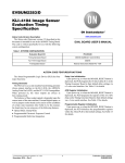
KAI−1003 TIMING
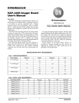
Line Table 0 (Integration)
Line Table 0 is the Integration timing sequence, during
which both the Vertical and Horizontal clocks are inactive.
V1_CCD
This sequence runs until Integration is complete, signaled by
the assertion of the VD_TG signal from the Altera PLD.
VMID
(Vclks not active)
V2_CCD
VLOW
HCLK_ENABLE
H1_HIGH
H1A_CCD, H2B_CCD*
(Hclks not active)
H2A_CCD, H1B_CCD*
H2_LOW
0
LT0 Entry
1
Pix Counts
(not to scale)
* In Single Channel Mode
Polarity is reversed for H2B_CCD and H1B_CCD for Dual Channel Mode
Figure 4. Line Table 0 Default Timing
Line Table 1 (Diode Transfer)
Line Table 1 is the Photodiode Transfer timing, in which
the V2 clock 3rd-level shifts charge from all the photodiodes
into the vertical CCD registers. The V1 and V2 clocks have
overlap adjustability to compensate for the clock driver rise
and fall times. Horizontal Clocks are inactive during the
Diode Transfer sequence.
V1_CCD
V2_CCD
HCLK_ENABLE
H1A_CCD, H2B_CCD*
H2A_CCD, H1B_CCD*
LT1 Entry
0
Pix Counts
1
Symbol
1
2
3
4
5
6
800
1
358
1
300
800
TPD2
TPD3
T PD1
T V2H
(not to scale)
* In Single Channel Mode
Polarity is reversed for H2B_CCD and H1B_CCD for Dual Channel Mode
Figure 5. Line Table 1 Default Timing
http://onsemi.com
14
EVBUM2268/D
Line Table 2 (Line Transfer)
Line Table 2 is the Line Transfer timing sequence that
transfers one entire row of charge toward the horizontal
register. V1 and V2 are asserted, with overlap adjustability
to compensate for the clock driver rise and fall times. Charge
is moved down the vertical CCD registers, and the last row
of charge is dumped into the horizontal register. The VCCD
clocking interval is followed by the Horizontal clocks,
which shift one line out through the output amplifier.
V1_CCD
V2_CCD
HCLK_ENABLE
H1A_CCD, H2B_CCD*
H2A_CCD, H1B_CCD*
LT2 Entry
0
1
2
3
Pix Counts
1
1
38
1
Symbol
4
30
TV
T HD
(not to scale)
* In Single Channel Mode
Polarity is reversed for H2B_CCD and H1B_CCD for Dual Channel Mode
Figure 6. Line Table 2 Default Timing
Line Table 3 (Binning Mode Line Transfer)
are shifted out. Horizontal Binning is controlled within the
Frame Table (Frame Table 1). Binning by 2 in the Horizontal
direction is achieved by clocking the Reset gate at half the
rate of the Horizontal clocks, thus transferring two
horizontal pixels onto the floating diffusion for every one
Reset pulse.
Line Table 3 is the Binning Mode Transfer sequence,
during which the Vertical clocks are asserted twice. Pulsing
the Vertical Clocks twice dumps two lines of charge onto the
Horizontal CCD, thus providing a 2× vertical binning factor.
The Horizontal clocks are run in Binning Mode as the pixels
V1_CCD
V2_CCD
HCLK_ENABLE
H1A_CCD, H2B_CCD
H2A_CCD, H1B_CCD
LT3 Entry
0
1
2
3
4
5
6
7
8
Pix Counts
1
1
38
1
40
1
38
1
30
Symbol
TV
TV
(not to scale)
Figure 7. Line Table 3 Default Timing
http://onsemi.com
15
TV
THD
EVBUM2268/D
Frame Table 0 Sequence
Transfer sequence clocks out all lines of the CCD imager
array. Once a full frame read out is complete, the KSC−1000
returns to Integration and waits for the Altera PLD to assert
the VD_TG signal to indicate the end of integration. Frame
Table 0 is used for both Single and Dual Channel readout, as
the sequence is exactly the same for both modes and only the
polarity of H1B and H2B are reversed.
Frame Table 0 contains the Single or Dual Channel timing
sequence used to continuously read out all rows of the CCD.
The sequence begins with the Integration sequence. Upon
receiving the VD_TG pulse, the Diode Transfer sequence
moves charge from the photodiodes into the light shielded
vertical CCDs. Once charge is in the vertical CCDs, the Line
Altera PLD
State Machine Sequence
TIMED_
INTEGRATION
KSC−1000TG
Frame Table 0 Sequence
ENTRY 0
Yes
DIO[11..7] =
{1,2,...7}?
Execute LT0
(INTEGRATE)
Wait for TG from PLD
No
Set INTEGRATE
Wait for INT ctr
VD_TG
ENTRY 1
Execute LT1
(DIODE XFR)
Count = 1
Issue VD_TG
Reset INTEGRATE
DIODE_
TRANSFER
Wait for
FRAME_VALID
(rising edge)
FRAME_VALID
Shutter?
Set INTEGRATE
on INTG_START
(falling edge)
LINE_
TRANSFER
ENTRY 2
Execute LT2
(LINE XFR)
Count = 1056
Issue
INTG_START
INTG_START
Wait for FRAME_VALID
(falling edge)
ENTRY 3
FRAME_VALID
Jump to FT0 Entry 0
Figure 8. Single and Dual Channel Mode Timing Sequence
http://onsemi.com
16
‘
EVBUM2268/D
V1_CCD
V2_CCD
H1A_CCD, H2B_CCD*
H2A_CCD, H1B_CCD*
CLPOB
PBLK
INTEGRATE
VD_TG
FRAME_VALID
LINE_VALID
FT0 Entry
0
1
Line Table
0
1
2
counts
x
1
1056
TIMED_INTEGRATION
DIODE XFR
LINE TRANSFER
PLD STATE
2
(not to scale)
* In Single Channel Mode
Polarity is reversed for H2B_CCD and H1B_CCD for Dual Channel Mode
Figure 9. Frame Table 0 Default Timing
Frame Table 1 Sequence
It is important to note that the KAI−1003 Device
Performance Specification illustrates a horizontal Binning
mode different than the one implemented in this Evaluation
Kit. In the device specification, binning is performed as
charge is shifted to Phase H22. Due to hardware limitations
on the KAI−1003 Imager Board, it is not possible to clock
Phase H22 as defined in the device specification, but binning
is still possible at the floating diffusion. The Reset pulse is
suspended every other pixel clock, thereby allowing two
packets of charge to dumped onto the floating diffusion
before it is sampled and then reset.
Frame Table 1 contains the 2×2 Binning Mode timing
sequence used to sum the charge collected in four photosites
into one CCD pixel. The sequence is essentially the same as
that of Frame Table 0, except that the Vertical Clocks are
asserted twice per line. This dumps charge from two vertical
CCD pixels into each Horizontal register CCD pixel.
The Horizontal CCD is clocked out using a binning readout
routine (See Figure 14). Since the Vertical Clocks are pulsed
twice for every Horizontal readout period, the entire CCD is
read with half the number of Vertical intervals. This
evaluation kit only supports Single Channel output when in
the Binning mode.
http://onsemi.com
17
EVBUM2268/D
Altera PLD
State Machine Sequence
TIMED_
INTEGRATION
KSC−1000TG
Frame Table 1 Sequence
ENTRY 0
Yes
DIO[11..7] =
{1,2,...7}?
Execute LT0
(INTEGRATE)
Wait for TG from PLD
No
Set INTEGRATE
Wait for INT ctr
VD_TG
ENTRY 1
Execute LT1
(DIODE XFR)
Count = 1
Issue VD_TG
Reset INTEGRATE
DIODE_
TRANSFER
Wait for
FRAME_VALID
(rising edge)
FRAME_VALID
Shutter?
Set INTEGRATE
on INTG_START
(falling edge)
LINE_
TRANSFER
ENTRY 2
Execute LT3
(LINE XFR BINNING)
Count = 528
Issue
INTG_START
INTG_START
Wait for FRAME_VALID
(falling edge)
ENTRY 3
FRAME_VALID
Jump to FT1 Entry 0
‘
Figure 10. Dual Channel Mode Timing Sequence
V1_CCD
V2_CCD
H1A_CCD, H2B_CCD
H2A_CCD, H1B_CCD
CLPOB
PBLK
INTEGRATE
VD_TG
FRAME_VALID
LINE_VALID
FT1 Entry
0
1
2
Line Table
0
1
3
Counts
PLD STATE
x
1
528
TIMED_INTEGRATION
DIODE XFR
LINE TRANSFER (Binning)
(not to scale)
Figure 11. Frame Table 1 Default Timing
http://onsemi.com
18
EVBUM2268/D
Electronic Shutter Timing
is inserted before the specified line, causing that particular
line time to be extended accordingly.
If the Integrate Start Pulse Line Number value in
Register 4 is set to 0, the Electronic Shutter will occur
immediately following the Diode Transfer sequence, before
the first line is read out. If the Integrate Start Pulse Line
Number value is greater than the number of vertical lines in
the Frame Table, there will be no Electronic Shutter. This is
the method used to disable the Electronic Shutter.
The electronic shutter timing is controlled by the values in
Register 3 of the KSC−1000. There are two methods of
actuating the Electronic Shutter pulse: by setting the
Integrate Start Pulse Line Number value in Register 4 so that
the pulse occurs on a specific line, or by setting the Force
INTG_START bit in a Frame Table entry. In either case, the
Electronic Shutter pulse setup, width, and hold times are
determined by the values in Register 3. The shutter sequence
V1_CCD
V2_CCD
Start of Integration
VSUB
H1A_CCD,
H2B_CCD*
H2A_CCD,
H1B_CCD*
Reg3 Entry
setup
width
hold
Pix Counts
30
150
20
(Line Table x)
(not to scale)
* In Single Channel Mode
Polarity is reversed for H2B_CCD and H1B_CCD for Dual Channel Mode
Figure 12. Electronic Shutter Timing
Horizontal Timing
mode. In Single Channel and Binning output modes, H1B
runs in phase with H2A while H2B is in phase with H1A. In
Dual Channel operation, the phases of H1B and H2B are
reversed, such that H1B clocks in phase with H1A and H2B
is in phase with H2A.
Figure 13 depicts the basic theoretical relationship
between the pixel-rate clocks to the CCD, the Video output
of the CCD, and the pixel-rate clocks to the AFE. Note that
the states of H1B and H2B are dependent on the operating
Vpix
Vsat
VOUTx_CCD
Tr
RESET_CCD
H2_CCD
Tpix
H1_CCD
Tshp
SHP
Tshd
SHD
DATACLK
* In Single Channel Mode
Polarity is reversed for H2B_CCD and H1B_CCD for Dual Channel Mode
Figure 13. Horizontal Timing
http://onsemi.com
19
EVBUM2268/D
Binning Mode Horizontal Timing
conversion. The KSC−1000 has the capability of
implementing the Horizontal Timing necessary to bin up to
four pixels. Horizontal Binning is controlled by setting bits
3:4 of the active Frame Table (Register 8) in the KSC−1000.
Figure 17 depicts the basic theoretical relationship between
the pixel-rate clocks to the CCD, the Video output of the
CCD, and the pixel-rate clocks to the AFE in 2× Horizontal
Binning Mode.
The Altera PLD default KSC−1000 settings contain 2×2
Binning Mode timing in Frame Table 1 (See Figure 12). In
order to activate the 2×2 Binning Mode, the Frame Table
Pointer (Register 0) must be changed to a value of 1. Setting
SW3 HIGH and pressing the BOARD_RESET button (S1
on the Timing Board) will load the binning mode default
values.
In order to sum the charge from two Horizontal CCD
pixels into one, the Reset clock is suspended on alternating
Horizontal clock cycles. In this way, two pixels of charge are
dumped onto the floating diffusion of the output amplifier
before this node is reset to VRD, the Reset Drain voltage.
See the KAI−1003 Device Specification [1] for further
details.
In order to correctly convert the output amplifier voltage
to digital data, the AFE clocks must be adjusted accordingly.
The Clamp pulse (SHP) samples the output after the Reset
pulse has been issued, but before the Horizontal clocks have
moved charge onto the floating diffusion. The Sample pulse
(SHD) samples the output after two Horizontal clock cycles
have moved two charge packets onto the floating diffusion.
The DATACLK then clocks the AFE to perform the
VOUT_CCD
Tr
RESET_CCD
H2A_CCD,
H1B_CCD
Tpix
H1A_CCD,
H2B_CCD
Tshp
SHP
Tshd
SHD
DATACLK
Figure 14. Binning Mode Horizontal Timing
Integration & Shutter Timing
Number value is set to 1280 the Shutter is never pulsed, as
this value exceeds the number of lines in a frame.
The BOARD_RESET switch must be pressed after
changing the DIO[11..7] bits in order for the change to the
KSC−1000 to take effect.
The Altera PLD controls the Integration time.
The KSC−1000 waits for a trigger signal (VD_TG) before
beginning the Diode Transfer sequence (See Figure 16).
The Altera PLD issues this trigger pulse when the
Integration Counter has reached a pre-programmed value, as
shown in Table 24. The Integration counter is clocked by an
internally generated 1 ms clock. The default value of 0
means that the VD_TG trigger is issued on the next rising
edge of the 1 ms clock after the frame readout is complete.
A value greater than 0 adds that many milliseconds to the
Integration Time, allowing Integration times greater than
8 seconds (Figure 18).
The default Integration Time in Single Channel Mode is
approximately one Frame Time, or the time between Diode
Transfers, during which the photodiodes are collecting
charge. This time may be decreased by use of the Electronic
Shutter, and may be increased by lengthening the Frame
Time. The user may control the Integration Time through the
DIO connector bits DIO[11..7]. This connector is optional,
and when disconnected, all bits are pulled LOW.
The available pre-programmed Integration Times are
detailed in Table 24.
The Electronic Shutter is controlled by changing the
Integrate Start Pulse Line Number value of the KSC−1000
Register 4. The Altera PLD has 8 pre-programmed Shutter
settings, controlled through the DIO[11..7] bits, as shown in
Table 14. These settings result in Integration times of one
Frame Time or less, in increments of 1/8 of the Frame Time
(See Figure 12). When the Integrate Start Pulse Line
http://onsemi.com
20
EVBUM2268/D
For any DIO[11.7] configuration, integration time for
Dual Channel and Binning modes are approximately half
that of the Single Channel mode. The shutter and integration
line numbers in Figure 16, Figure 17, and Figure 18 can be
generalized to represent Binning (Frame Table 1) mode by
replacing 1056 lines with 528 lines and dividing electronic
shutter line numbers by 2.
Table 24. PROGRAMMED INTEGRATION TIMES
DIO[11..7]
Int Count
1 Ch Mode Reg 4 Entry
1 Ch Mode Tint
2 Ch/Bin Mode Reg 4 Entry
2 Ch/Bin
Mode Tint
0 (Default)
0
1100 (Default – No Pulse)
63.00 ms
1100 (default – no pulse)
34.00 ms
1
0
924
7.86 ms
462
4.25 ms
2
0
792
15.75 ms
396
8.50 ms
3
0
660
23.63 ms
330
12.75 ms
4
0
528
31.50 ms
264
17.00 ms
5
0
396
39.38 ms
198
21.25 ms
6
0
264
47.25 ms
132
25.50 ms
7
0
132
55.13 ms
66
29.75 ms
8
1
1100 (Default – No Pulse)
64.0 ms
1100 (Default – No Pulse)
35.0 ms
9
3
1100 (Default – No Pulse)
66.0 ms
1100 (Default – No Pulse)
37.0 ms
10
5
1100 (Default – No Pulse)
68.0 ms
1100 (Default – No Pulse)
39.0 ms
11
10
1100 (Default – No Pulse)
73.0 ms
1100 (Default – No Pulse)
44.0 ms
12
25
1100 (Default – No Pulse)
88.0 ms
1100 (Default – No Pulse)
59.0 ms
13
50
1100 (Default – No Pulse)
113.0 ms
1100 (Default – No Pulse)
84.0 ms
14
70
1100 (Default – No Pulse)
133.0 ms
1100 (Default – No Pulse)
104.0 ms
15
100
1100 (Default – No Pulse)
163.0 ms
1100 (Default – No Pulse)
134.0 ms
16
200
1100 (Default – No Pulse)
263.0 ms
1100 (Default – No Pulse)
234.0 ms
17
300
1100 (Default – No Pulse)
363.0 ms
1100 (Default – No Pulse)
334.0 ms
18
400
1100 (Default – No Pulse)
463.0 ms
1100 (Default – No Pulse)
434.0 ms
19
500
1100 (Default – No Pulse)
563.0 ms
1100 (Default – No Pulse)
534.0 ms
20
600
1100 (Default – No Pulse)
663.0 ms
1100 (Default – No Pulse)
634.0 ms
21
700
1100 (Default – No Pulse)
763.0 ms
1100 (Default – No Pulse)
734.0 ms
22
800
1100 (Default – No Pulse)
863.0 ms
1100 (Default – No Pulse)
834.0 ms
23
900
1100 (Default – No Pulse)
963.0 ms
1100 (Default – No Pulse)
934.0 ms
24
1000
1100 (Default – No Pulse)
1.063 s
1100 (Default – No Pulse)
1.034 s
25
2000
1100 (Default – No Pulse)
2.063 s
1100 (Default – No Pulse)
2.034 s
26
3000
1100 (Default – No Pulse)
3.063 s
1100 (Default – No Pulse)
3.034 s
27
4000
1100 (Default – No Pulse)
4.063 s
1100 (Default – No Pulse)
4.034 s
28
5000
1100 (Default – No Pulse)
5.063 s
1100 (Default – No Pulse)
5.034 s
29
6000
1100 (Default – No Pulse)
6.063 s
1100 (Default – No Pulse)
6.034 s
30
7000
1100 (Default – No Pulse)
7.063 s
1100 (Default – No Pulse)
7.034 s
31
8000
1100 (Default – No Pulse)
8.063 s
1100 (Default – No Pulse)
8.034 s
http://onsemi.com
21
EVBUM2268/D
Integration Time vs. DIO[11:7]
10000
Time (ms)
1000
100
10
1 Ch Mode Tint
2 Ch/Bin Mode Tint
1
1
3
5
7
9
11
13
15
17
19
21
23
25
27
29
DIO[11:7]
Figure 15. Programmed Integration Times
V1_CCD
1
V2_CCD
VES (shutter)
2
1055
1056
Shutter Line = 1100 (No shutter pulse)
INTEGRATE
1ms Clock
VD_TG
FRAME_VALID
LINE_VALID
FT0 Entry
0
1
2
Line Table
0
1
2
Counts
x
1
1056
DIO[11..7]
0
(not to scale)
Figure 16. Single and Dual Channel Mode Default Integration Timing
http://onsemi.com
22
31
EVBUM2268/D
V1_CCD
1
V2_CCD
2
3
4
923
924
1055 1056
Shutter Line = 924
VES (shutter)
INTEGRATE
1ms Clock
Integration Count = 0
VD_TG
FRAME_VALID
LINE_VALID
FT0 Entry
0
1
2
Line Table
0
1
2
Counts
x
1
1056
DIO[11..7]
1
(not to scale)
Figure 17. Single and Dual Channel Mode Integration Timing with Shutter
V1_CCD
V2_CCD
(no shutter)
VES (shutter)
INTEGRATE
1ms Clock
Integration Count = 3
0
1
2
3
VD_TG
FRAME_VALID
LINE_VALID
FT0 Entry
0
1
2
Line Table
0
1
2
counts
x
1
1056
DIO[11..7]
9
(not to scale)
Figure 18. Single and Dual Channel Mode Extended Integration Timing
http://onsemi.com
23
EVBUM2268/D
BOARD INTERFACE CONNECTOR SIGNAL MAP
For reference, the board interface timing signals from the
3F5054 Timing Board to the 3E8214 Imager Board are
shown in Table 25. Note that the power connections are not
shown here.
Table 25. TIMING BOARD/IMAGER BOARD SIGNAL MAP
AD9945 KSC−1000 Timing Board
KSC−1000
Signal Name
KAI−1003 Imager Board
LVDS Interface
Signal Name
3F5592 J5 Pins
3E8214 J3 Pins
LVDS Interface
Signal Name
Imager Board
Signal Name
TIMING_OUT0
1/2
1/2
INTG_START
TIMING_OUT1
5/6
5/6
VES ±
VES
V6
TIMING_OUT2
9/10
9/10
FDG ±
FDG (Not Used)
V1
TIMING_OUT3
13/14
13/14
V3RD ±
V3RD
V2
TIMING_OUT4
17/18
17/18
V2B ±
V2B (Not Used)
V3
TIMING_OUT5
21/22
21/22
V2 ±
V2
V4
TIMING_OUT6
25/26
25/26
V1 ±
V1
RG
TIMING_OUT7
29/30
29/30
R±
RESET
H1
TIMING_OUT8
33/34
33/34
H2B ±
H2B
H4
TIMING_OUT9
37/38
37/38
H2A ±
H2A
H2
TIMING_OUT10
41/42
41/42
H1B ±
H1B
H3
TIMING_OUT11
45/46
45/46
H1A ±
H1A
TIMING_OUT12
51/52
51/52
TIMING_OUT13
55/56
55/56
TIMING_OUT14
59/60
59/60
TIMING_OUT15
63/64
63/64
TIMING_OUT16
67/68
67/68
TIMING_OUT17
71/72
71/72
TIMING_OUT18
75/76
75/76
TIMING_OUT19
79/80
79/80
http://onsemi.com
24
EVBUM2268/D
VIDEO SIGNAL PATH
The gain of the hardware signal path is designed so that the
saturation output voltage of the KAI−1003 will not overload
the AFE input. The AFE default VGA gain is set to 2.0
(6.0 dB) using a gain code of 20 to maximize the dynamic
range of the AFE (See Table 9 and References).
The entire video signal path through the Imager Board and
Timing Board is represented in Figure 19. The individual
blocks are discussed in the Imager Board User Manual and
the Timing Board User Manual.
The hardware gain for the entire pre-AFE signal path can
be calculated by multiplying the gains of the individual
stages:
0.96
1.25
0.5
1.25 + 0.75
(eq. 1)
Imager Board
Timing Board
+15V
VOUT_CCD
CCD
ÌÌÌÌÌ
+5V
−
+
−5V
Emitter−Follower
Av = ~0.96
Coax Cable
(75ohm, terminated)
Av = 0.5
Op−Amp Buffer
Av = 1.25
+5V
−
Analog Digital
Front End Out
+
−5V
Op−Amp Buffer
Av = 1.25
AFE
(prog. gain)
Figure 19. Video Signal Path Block Diagram
WARNINGS AND ADVISORIES
Generator Board firmware. ON Semiconductor can only
support firmware developed by, and supplied by,
ON Semiconductor. Changes to the firmware are at the risk
of the customer.
When programming the Timing Board, the Imager Board
must be disconnected from the Timing Board before power
is applied. If the imager Board is connected to the Timing
Board during the reprogramming of the Altera PLD, damage
to the Imager Board will occur.
Purchasers of a ON Semiconductor Evaluation Board Kit
may, at their discretion, make changes to the Timing
ORDERING INFORMATION
ON Semiconductor reserves the right to change any
information contained herein without notice. All
information furnished by ON Semiconductor is believed to
be accurate.
Please address all inquiries and purchase orders to:
Truesense Imaging, Inc.
1964 Lake Avenue
Rochester, New York 14615
Phone: (585) 784−5500
E-mail: [email protected]
http://onsemi.com
25
EVBUM2268/D
REFERENCES
[1] KAI−1003 Device Specification
[2] KAI−1003 Imager Board User Manual
[3] KAI−1003 Imager Board Schematic
[4] AD9945 Timing Generator Board User Manual
[5] AD9945 Timing Generator Board Schematic
[6] Analog Devices AD9945 Product Data Sheet
ON Semiconductor and the
are registered trademarks of Semiconductor Components Industries, LLC (SCILLC) or its subsidiaries in the United States and/or other countries.
SCILLC owns the rights to a number of patents, trademarks, copyrights, trade secrets, and other intellectual property. A listing of SCILLC’s product/patent coverage may be accessed
at www.onsemi.com/site/pdf/Patent−Marking.pdf. SCILLC reserves the right to make changes without further notice to any products herein. SCILLC makes no warranty, representation
or guarantee regarding the suitability of its products for any particular purpose, nor does SCILLC assume any liability arising out of the application or use of any product or circuit, and
specifically disclaims any and all liability, including without limitation special, consequential or incidental damages. “Typical” parameters which may be provided in SCILLC data sheets
and/or specifications can and do vary in different applications and actual performance may vary over time. All operating parameters, including “Typicals” must be validated for each
customer application by customer’s technical experts. SCILLC does not convey any license under its patent rights nor the rights of others. SCILLC products are not designed, intended,
or authorized for use as components in systems intended for surgical implant into the body, or other applications intended to support or sustain life, or for any other application in which
the failure of the SCILLC product could create a situation where personal injury or death may occur. Should Buyer purchase or use SCILLC products for any such unintended or
unauthorized application, Buyer shall indemnify and hold SCILLC and its officers, employees, subsidiaries, affiliates, and distributors harmless against all claims, costs, damages, and
expenses, and reasonable attorney fees arising out of, directly or indirectly, any claim of personal injury or death associated with such unintended or unauthorized use, even if such claim
alleges that SCILLC was negligent regarding the design or manufacture of the part. SCILLC is an Equal Opportunity/Affirmative Action Employer. This literature is subject to all applicable
copyright laws and is not for resale in any manner.
PUBLICATION ORDERING INFORMATION
LITERATURE FULFILLMENT:
Literature Distribution Center for ON Semiconductor
P.O. Box 5163, Denver, Colorado 80217 USA
Phone: 303−675−2175 or 800−344−3860 Toll Free USA/Canada
Fax: 303−675−2176 or 800−344−3867 Toll Free USA/Canada
Email: [email protected]
N. American Technical Support: 800−282−9855 Toll Free
USA/Canada
Europe, Middle East and Africa Technical Support:
Phone: 421 33 790 2910
Japan Customer Focus Center
Phone: 81−3−5817−1050
http://onsemi.com
26
ON Semiconductor Website: www.onsemi.com
Order Literature: http://www.onsemi.com/orderlit
For additional information, please contact your local
Sales Representative
EVBUM2268/D