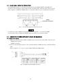
1
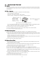
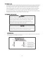
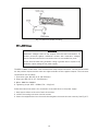
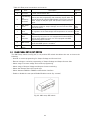
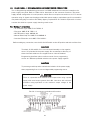
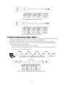
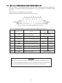
Fig. 3-6: Bus-bars shield mounting
80V to 600V Models
WARNING
Hazardous voltages exist at the outputs and the load connections. To
protect personnel against accidental contact with hazardous voltages,
ensure that the load and its connections have no accessible live parts.
Ensure that the load wiring insulation rating is greater than or equal to the
maximum output voltage of the power supply.
The 80V to 600V models have a four terminal wire clamp output connector. The two left terminals
are the positive outputs and the other two right terminals are the negative outputs. The connector
requirements are as follows:
1. Connector type: GIC-2.5/4-G-7.62 (Phoenix).
2. Plug type: GIC-2.5/4- ST-7.62 (Phoenix).
3. Wires: AWG12 to AWG24.
4. Tightening torque: 0.55 - 0.59Nm (5.6 - 6.1kgf・cm).
Follow the below instructions for connection of the load wires to the power supply:
1. Strip approx.10mm at the end of each of the wires.
2. Loosen the mating connector terminal screws.
3. Insert the stripped wires into the terminal and tighten the terminal screw securely (see Fig.3-7).
16