1
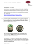
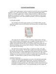
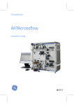
MODEL ECD-200
ELECTROCHEMICAL DETECTOR
USER'S MANUAL
349 N Science Park Rd., State College PA 16803
Phone: 800-345-5557 / 814-234-7317 Fax: 814-238-6072
www.laballiance.com
INTRODUCTION
We remind to you that the model ECD-200 must be
standardized and checked by the user.
LabAlliance is not responsible for wrong results due
to a bad standardization.
This instrument is guaranteed for one year against
defects in materials and workmanship.
This guarantee does not include the glassy carbon
working electrode, the reference electrode, and the
auxiliary electrode.
For any inquiry or request for repair service, contact
your Distributor.
CONTENTS
1. OVERVIEW
1.1
1.2
1.3
The electrochemical detection in HPLC
Unpacking
Technical data
2. THE ELECTROCHEMICAL CELL
2.1
Setting up of the cell
2.2
Mounting of the cell
3. THE EL ECTRODES.
3.1
3.2
3.3
Reference electrode
Working electrode
Auxiliary electrode
4. ELECTRICAL CONNECTIONS
4.1
Power connection
4.2
Connecting the cell
4.3
Connecting the recorder / integrator
5. PUNCTIONS OF THE MODEL ECD-200
5.1
Description
5.1.1
Front panel (Fig 2 page 10)
5.1.2
Rear panel (Fig 3 page 17)
5.2
Faraday cage (Fig 4 page 18)
6. OPERATION
6.1
6.1.1
6.2.2
6.2
6.3
6.4
Starting up
Setting of the cell
Switching on
Selection of the parameters
Selection of the sensitivity
Shutting down of the detector
7. FIGURES
7.1
7.2
Rear panel
FARADAY cage
8. TROUBLESHOOTING
9. MAINTENANCE
9.1
9.1.1
9.1.3
9.1.4
9.2
9.2.1
9.2.2
9.2.3
9.2.4
10. R. S. 232 COMMANDS
Maintenance of the cell
Replacement of the PTFE seal
Cell leakage
Air bubbles
Maintenance of the electrodes
Reference electrode RE3
Working electrode
Auxiliary electrode
Electronic test control
10.1
10.2
10.3
10.4
1
Connection
Syntax Parameters
Shared commands
Specific commands for the detector
OVERVIEW
1.1
Electrochemical detection in HPLC.
Even if you are very familiar with electrochemistry, it is essential that you
read this user’s guide to get the best results from the Model ECD-200.
1.2
Unpacking
Upon receipt of your instrument, unpack the unit carefully, inspect it for
possible damage and check the content of the carton against the list
joined. Report any loss or damage immediately to the distributor you
purchased the unit from.
Potential range: +/- 2 volts by steps of 10 mv
Liquid crystal display:
The
The
The
The
The
The
The
LCD unit is used to display:
value of the output in V or nA/V.
value of the offset.
time constant.
withdraw of the base line.
chromatogram.
sensitivity
Sensitivity: 0.05 nA/v to 200 nA/V by 12 steps.
Autozero: Actuated by the key board or the injector.
Time constant: 0.5s; 2s; 5s.
Event marker: By the key board or the injector.
Withdraw of the base line: +/-0.9 V by 10 mV steps
Two methods saved.
Output 1 V or 10 mV FS.
Output RS 232 C.
Accessory kit which include:
Electrochemical cell
Reference electrode (2) with O-ring
Teflon tubing
Fingertights fittings
Polishing kit
2
OVERVIEW
2.1
Setting up of the cell
The electrochemical cell is a thin layer type, made up of two
blocks.
Upper-half block: auxiliary electrode. Made in
stainless steel.
Lower-half block: Block with the working electrode.
Figure 1. Electrochemical Cell Assembly
Our cells are equipped with PTFE fittings (Ref F 100 available from
all the suppliers of HPLC. The Model ECD-200 is compatible with
almost all the chromatographs.
2.2
Mounting the cell
The cell is located on the right side of the model ECD-200 in a
Faraday cage to minimize electromagnetic interferences. This
compartment is large enough to contain a chromatographic column.
The door of the cage is removable for making adjustments to the
cell and connectors, but must be hold in place when running the
detector.
The cell is delivered ready to use:
Make the hydraulic connections with the Teflon tubing and the
Fingertights, the inlet is located in the stainless steel block and the
outlet in the PTFE block.
Set up the electrical connections:
Black plug: Working electrode
Blue plug: Auxiliary electrode
Place the cell in his holder. Turn on the pump. With the mobile
phase flowing through the hole of the reference electrode, insert
the O-ring into the base of the reference electrode port, take off the
plastic cap at the bottom of the electrode and carefully screw the
electrode in this port. Finger tightening the reference electrode will
ensure a leak proof seal.
Never use a wrench because it may cause the break of the
electrode.
Connect the white plug to the reference electrode.
Close the Faraday cage, placing the tubing in the access located
on the bottom of the cage door.
The cell is ready to be switched on.
3
THE ELECTRODES
3.1
Reference electrode RE3 (Type Ag/AgCl/Cl¯)
The body of the cell is made in Kel-F. The electrode is shipped dry and
must then be filled up before use with the NaCl (3M) solution provided in
the kit. The junction at the bottom of the electrode is in VYCOR and must
be kept wet.
If the detector must be switched off for more than 24 hours, it is better to
remove the electrode from the cell and to replace the plastic cap
previously filled with the NaCl solution.
The channel inside of the electrode is very small and you can check if
there are trapped air bubbles at the bottom of the electrode by gently
tapping it while it is vertical. The electrode must always be positioned
vertically on the top of the cell.
3.2
Working electrode
The working electrode is embedded in the lower block of the cell. This
electrode may be in glassy carbon, gold, platinum, silver, or any kind of
material on special request.
3.3
Auxiliary electrode
The entire upper block in stainless steel is the auxiliary electrode. It
contains the mobile phase inlet port, a port for the reference electrode
and a hole for the electrical connection.
4
ELECTRICAL CONNECTORS
4.2
POWER
110-120 OR 220-240 V 50/60 Hz Selectable. The detector must be
grounded. The color code for the power cord is:
Red or Brown
Phase
Black or Blue
Neutral
Green or Yellow
Ground
Warning: Read carefully the set up instructions before you switch on the
power. The Model ECD-200 measures very small currents, as the
conducting solvent is flowing through all the chromatograph, so it is
important to insure that all the elements are connected to the same
ground, avoiding the loops of current.
4.2
Connecting the cell
The connecting cable is a three-wire with banana plugs that must be
connected as follows:
BLACK
BLUE
WHITE
Working electrode
Auxiliary electrode
Reference electrode
Warning: Never short circuit two electrodes when the power is switched
on.
4.3
Connecting to a recorder or an integrator
Two analog signals output are available on the rear panel: 10 mV or 1 V.
You can use a simple two-wire cable supplied with the detector.
5
FUNCTIONS OF THE MODEL ECD-200
5.1
Description
Model ECD-200 is a microprocessor-controlled detector. A soft-touch key board on
the front panel allows all the operations in local mode . For remote operations a computer
is linked to the detector by a RS232 cable
5.1.1
Front panel (fig 2 page 10
1
2 to 11
2
3 to 6
7
8
9
10
11
: LCD screen.
: Soft-touch keys
: Menu Displays various menu.
: F1 to F4 functions keys depends on the
menu selected.
: Cell switch on the cell
: SENS call up the sensitivity (and
baseline offset)selection menu
: Autozero reset the baseline to a
predetermined value .
: Event marker, perform 3 functions
(also available externally)
1) Reset the clock to zero
2) Makes an auto zero
3) Marks the chromatogram.
: Time, reset the clock to zero.
Six light emitting diodes:
12
13
14
15
16
17
: ON Green: The cell is on.
: OFF Red: The cell is off
: Overload Current cell is too high.
: Autozero Red Now generating an auto
zero (Blocks the other functions).
:Local Green :Control is from the
keyboard.
: Remote Green: Control is from a
computer.
5.1.2
1.
2.
3.
4.
5.
6.
5.2
Rear panel (Fig 3 page 17
Power switch
Power input
Fuse box
RS 232 socket
Analog output 1 V/FS; 10 mV/FS
External event marker
FARADAY Cage
Located on the right side of the detector, the Faraday cage is fitted to hold the cell
and eventually the column.
A dummy cell is located on the side of the cage and allows you to perform tests.
6
OPERATIONS
6.1 Starting up.
Before starting-up, please read carefully this chapter to get the best results with
Model ECD-200.
6.1.1 Set the cell in his holder (See 2.2).
6.1.2 Switch the power to ON (Fig 3)
The LCD screen briefly display "PRECISION INSTRUMENTS" while making an auto
test.
6.2 Selection of the parameters
After the test the screen display a preselected working method kept in the memory, the
use of this function will be explained later.
On this screen using the function keys the user can select several parameters:
F1, F2 are used to set the luminosity on the LCD screen.
F3 is used to select the time of the chromatogram displayed on the screen: 1;
5; 15; 30; 60 mn. The selected value is displayed in 1.
F4 is used to select the value of the time constant: 0; 0.5 ; 2,5 s . Value
displayed in 2 .
Pressing the MENU key one time displays the POT screen.
MENU POTENTIAL
The POT screen is used to set the value and the polarity of the potential applied to the
working electrode.
F1
Increase the value of the potential applied to the working electrode.
F2
Decrease the value of this potential.
F3
Select the polarity of the potential A sign -before the value appeared
when the reduction mode have been selected.
F4
Set an automatic auto zero each time the
sensitivity is changed.
Pressing the menu key displayed the METHOD screen.
MENU METHOD
Only the function line is modified. This menu is used to store, and recall, a set of
parameters in either of two memories. This method is useful for the users working in
routine on one or two products. F1 Introduce the parameters displayed on the
screen in the memory. F3 Recall automatically this method. Another method may be
selected using the F2 and F4 keys
Pressing the MENU key displayed the VISU screen.
The visual screen is used to configure the display by selecting the parameters
displayed on the left part on the screen when the right one is occupied by the
chromatogram.
F1 Select the value of the output signal in nA or in V.
F2 Value of the offset in nA or in V.
F3 Indication of the working potential or the offset on the left part of the screen.
F4 Switches the chromatogram display on/off
At this time you can select the sensitivity by pressing directly the key SENS (8 fig 2)
This menu set up the sensitivity to start the analysis, generally 200 nA and should
be recall at any time using the same key: SENS.
F1 Increase the displayed value
F2 (-) Decrease the value
F3 (Base line +) Move the base line to the left of the screen by steps of 10mV.
F4 (Base line -) Same function to the right
At this time all the parameters have been selected if the user want to save these values
he have to press the key MENU until the METHOD screen is displayed and introduce
these values in the memory.
A second line of keys allows a direct access to precise functions:
CELL Switches the cell on or off the led lights green or red according to the
choice.
SENS Set the sensitivity and move the base line
AUTOZERO Bring back the base line to a previous value.
EVENT MARKER.
TIME Reset the clock to zero.
6.3
SELECTION OF THE SENSITIVITY
When all the parameters have been introduced, and the cell switch on, a
strong current should be obtained which must decrease to a constant value giving a
flat base line
6.4
SHUTTING DOWN OF THE DETECTOR
To stop the system: Depress the key CELL, the red led OFF lights. Switch
off the main power. Stop the flow.
Note: If you are not shutting down the system for a long time , it is better to
reduce only the flow rate of the mobile phase a minimum to keep the cell in a stable
condition.
CAUTION: Saline solutions are used with electrochemical detection. For this
reason, when you stop the HPLC system you must wash carefully the system to
avoid the build up of crystal and salt deposits.
7
FIGURES
7.1 Rear panel (fig 3)
1.
2.
3.
4.
5.
6.
Power switch.
Power input.
Fuse holder.
RS 232 connection.
Recorder/ integrator output 1 V/FS, lOmV/FS.
External event marker.
7.2 FARADAY CAGE
Fig 4 FARADAY CAGE (Side View)
1.
Outlet fitting
2.
Black banana plug: working electrode
3.
Blue banana plug: auxiliary electrode
4.
White banana plug: reference electrode
5.
Cell
6.
Reference electrode
7.
Dummy cell
8.
Cell holder
9.
Tubing access holes
10.
Inlet fitting
8
TROUBLESHOOTING
Problem
Possible Cause
Solution
No detector response
Power cord disconnected.
Power OFF.
Fuse blown.
Voltage set incorrectly.
Working electrode not ON
Reconnect the cord.
Switch ON at rear panel.
Replace the fuse.
Check, correct
Press soft touch 'Cell',
green LED is lit when ON.
Reconnect the jack plug.
Replace the electrode.
Check/install pulse damper.
Locate and remove.
Drop in mobile phase flow.
Baseline oscillations
Sudden shift of bezel
Working electrode
disconnected. Working
electrode damaged. Pulsations
caused by pump.
Air bubbles in system.
Check pumping system.
Flattening of peaks
Too much sample.
Saturation of detector
Output
Cell incorrectly connected.
Faulty reference electrode.
Check reservoir is not empty.
Reduce sample size, or dilute it,
reduce to 100 ng or less.
Check electrical connec6ons. (jack
plugs) to cell.
Remove trapped air bubbles.
Replace reference electrode.
Regenerate working electrode.
Faulty working electrode.
Baseline unstable
Trapped air bubble in cell.
Air bubbles in outlet tubing,
Insufficient liquid in reference
electrode assembly.
Formation of crystals around
reference electrode assembly.
Baseline noisy.
High level of
background noise
Hydraulic problems (leakage).
Metallic Particles in hydraulics
Inadequate grounding.
Contamination of the
mobile phase.
Turn OFF, and eliminate bubbles.
Degas mobile phase. Check
hydraulic connections.
Refill with NaCI (3m) solution
or replace assembly.
Remove it, clean well with H20
(distilled). Refit, making sure
mobile phase does lot leak out.
Tighten tubing connections.
Clean system, change frits, etc.
Make new mobile phase using very
pure compounds.
9
9.1
9.1.1
MAINTENANCE
Maintenance of the cell
Replacement of the PTFE seal.
Place the PTFE gasket on the stainless steel half block, line up the sides of
the gasket with the sides of the block . The wider end of the gasket should be
nearest the reference electrode port . The PTFE gasket is asymmetrical, be sure
the two small holes on the stainless steel block are visible in the channel in the
middle of the seal.
Place the Kel-F block on the stainless steel block so that the gasket is
between the two blocks and the port for the reference electrode is lined up with the
mobile phase outlet in the Kel-F half block.
Return the four screws to the Kel-F block, tighten the screws gradually by alternately
tightening the screws which are diagonally across from one another until firm.
Caution: Over-tightening the screws can break the cell.
9.1.2
Cell leakage.
Clean carefully the parts of the block in contact with the gasket, and
replace the seal.
9.1.3
Air bubbles.
Air bubbles can significantly degrade the performances of the detector;
bubbles can be formed by a non degassed mobile phase The mobile
phase can be degassed under vacuum or by increasing the temperature
for a short time for aqueous solvent, if the mobile phase contain an
amount of organic solvent it is better to use an ultrasonic bath or to flush
the solution with a gentle bubbling of helium.
9.2 Maintenance of the electrodes
The life of the electrodes depends mainly of the operating conditions, the
quality of the solvents and the conductive salt . Although special care is
taken in the manufacture of the electrodes no guarantee can be given as
to the lifetime of any electrode.
9.2.1
Reference electrode RE3
This electrode act as half a cell, so before mounting the electrode in his
port it is very easy to control his potential. You take two reference
electrodes, you dip the bottom of the electrode in a NaCl solution, and
you measure the potential difference between the electrode using an
external voltmeter. This difference must not be higher than 75 mV, if not
change the electrode So it is advisable to have several electrodes in
stock
9.2.2
Working electrode.
The thin layer type cell allows an easy maintenance of the working
electrode. A loss of sensitivity points to the necessity of replacing the
electrode.
1-Press the key CELL the red led OFF lights
2-Disconnect the three jacks connectors.
3-Remove the cell and disconnect the inlet and outlet tubing.
4-Unscrew the reference electrode and refit the plastic cap.
5-Unscrew the four screws, which hold the two half blocks together,
using the Allen key.
The working electrode can be rendered passive by
sample molecules or by products fixed on the surface . It
can be regenerated as follow:
1-Assemble the polishing pad from the kit provided
2-Put one or two drops off the polishing alumina on
the wet pad .
3-Polish the electrode by gently rubbing the side
containing the glassy carbon electrode on the
pad for about one minute .
4-Rinse the electrode with distillated water and
reassemble the cell.
9.2.3
AUXILIARY ELECTRODE
Generally this electrode don't need any maintenance,
but you can clean it at the same time for working
electrode and using the same polishing kit .
9.2.4
Electronic test control.
Each time that the detector is started up, the electronics are automatically
tested. To check that the electronics are working correctly:
1-Switch off the detector (Power switch on the rear panel).
2-Remove the connectors from the cell and then connect them to the dummy
cell inside the FARADAY cage . Each jack connects to the socket having the
same color (blue white, black
3-Switch on the detector.
4-Move through the screen until you get to the POTENTIAL screen select a
potential of 0.50 v
5-Start up the cell by pressing the CELL soft touch key, the green LED lights up.
6-Push the AUTO ZERO key, the red auto zero LED lights indicating an auto
zero is being generated
7-When the red light goes out check the output value is near zero and check the
OFFSET is 0.50 V +/-10%
10
RS232 COMMMDS
10.1 Connection
The connection is made by a standard 9 pins RS232 cable between the female socket
at the rear of the detector and the computer. The data transmission rate is 4800 Baud (7
data bits, 1 parity bit and 1 stop bit)
The pin out of the 9-pin socket is as follows:
Pin 2 receive data
Pin 3 transmit data
Pin 4 data terminal ready
Pin 5 ground
Pin 8 clear to send
10.2 Syntax, parameters
A maximum of 16 commands may be used. Each command is made up of 16
characters (maximum) terminated by a carriage return (CR), and may include up to 3
parameters. For example:
Function
Parameter 1 Parameter 2 Parameter 3 CR
Where CR=OD hexadecimal, and Function is an alphabetic character code that definite
the type of command that is to be executed
Five types of parameters exist
-Represented by the notation @: switches, which are used to switch between
two possible states. These consist of one byte taking either ASCII character 11111 (31 hex),
or ASCII’1211 (32 hex); In the case where the switch can be left unchanged this word
takes ASCII character “9” (39 hex).
-Represented by the notation **: Integers, which are used to determine whole
number, consisting of a fixed number of bytes (n) able to take ASCII character “0” to “9”.
-Represented by the notation #.### :actual values, consisting of a fixed number
of bytes (n) a decimal point (2E hex), and a fixed number of bytes(m).
-Represented by the notation +###.## :actual value and sign, consisting of a
fixed number of bytes (n), a decimal point (2e hex) and a fixed number of bytes
(m),preceded by the sign indicator This character is either - (2D hex) or
+(2B hex) .
-Represented by the notation xxxx :text, all ASCII characters between 20 hex
and 7E hex.
10.3
Shared commands
Following are the shared commands of the electrochemical detector
R
Change to remote mode
L
Change to local mode
A
Send auto zero command
D+##
Set the output offset(-0.95 to +0.95 in steps of
0.05)
F* Set the value of the filter, may take the values: 0
0= no filter
1 = 0.5 s
2= 2s
3= 5s
I Identification check; returns the programmed string, by default D= detector
JXXXX Programming identification: xxxx= a string of characters between 1 and
10.
10.4
C@
Specific commands of the detector
Switch the cell ON and OFF
@=1 cell off
@=2 cell on
S@@* Enable automatic auto zero
Activate /Disactivate the graphical display
(plot)and (optionally) fix the duration of trace .
@=I automatic auto zero OFF
@=2 automatic auto zero ON
@=I disactivate, the plot
@=2 activate the plot
*=O(lmn),1(5 mn),2(15mn),3(30mn)4(60mn)
Z@@@ Set the display options.
@=1 displays the offset value in nA
@=2 displays the offset value in volts
@=1 displays the potential in volt on the right
@=2 displays the potential in volt on the left
@=1 displays the offset value on the left
@=2 displays the offset value on the right
G**
Set the range
10
12
14
16
18
20
200 nA/V
50
10
2
0.5
0.1
11
13
15
17
19
21
100 nA/V
20
5
1
0.2
0.05
P@#.## Set to either oxidation or reduction and set the potential value
@=1 reduction @=2 oxidation #.##=Potential value between 0.00 end 2.54.