1
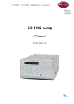
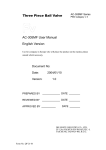
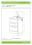
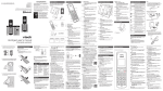
T +31 71 5813333 | F +31 71 5813334 | [email protected] | www.myAntec.com
SENCELL QUICK-START GUIDE
TM
Congratulations on your purchase of the SenCell , a new electrochemical flowcell for (U)HPLC with
ECD. The SenCell has several unique features (Patent Pending) like a stepless adjustable working
volume (spacerless concept) and toolless assembly . This document contains important information
how to get started with the SenCell. Note that this document is not a replacement of the user manual,
please consult the user manual for detailed information about the SenCell. The user manual and
additional instruction videos can be found online on the Antec website (access only for registered
users, registration is free):
http://www.myantec.com/support/docs-and-downloads/user-manuals
http://www.myAntec.com/support/maintenance-videos/sencell-instruction
This hardware should be used by trained laboratory personnel only. Use proper eye and skin
protection when working with solvents. Additional safety requirements or protection may be
necessary depending on the chemicals used in combination with this equipment. Make sure
that you understand the hazards associated with the chemicals used and take appropriate
measures with regards to safety and protection.
The SenCell is delivered pre-assembled and ready for installation and use.
Fig 1. Left side: photo of assembled SenCell inlet block (green) with In-Situ Ag/AgCl (ISAAC)
reference electrode (REF). Right side: bottom side of the SenCell with the Cell working volume
adjustment system, Auxiliary(AUX) electrode contact (opening on left side next to inscription ‘3’) and
Working electrode (WE) contact (opening in the center).
The working volume is pre-set at the factory at position 2 (figure 1 right side) corresponding with a
spacing of approximately 50 ± 10 µm. This setting is advised when using the SenCell in combination
with standard bore LC columns (2 mm – 4.6 mm ID) and flow rates > 200 µL/min. When using micro
bore LC columns position 1 ( 25 ± 10 µm) is advised as working volume. See instructions in the next
section how to adjust the working volume.
Document 116.0014 rev 03
Page 1 of 4
ADJUSTING THE CELL WORKING VOLUME
Fig 2. Adjustment of the working volume from position 2 (left side) to 1 (right side).
To adjust the working volume from position 2 to 1:
1. Insert pins of the adjuster tool (p/n 116.1015) in the two holes on the bottom side of the
SenCell. Note that the diameter of the two pins differ. The larger diameter pin should be
inserted in the AUX contact.
2. Turn the adjuster tool counter clock wise until the marker on the outer metal ring is exactly
aligned with the marker indicating position 1 (red arrow).
3. Remove the adjuster tool.
Applying small working volume settings should be done with great care, it may cause
excessive pressure built-up over the flow cell, excessive baseline noise and may damage the
cell. DO NOT OPERATE THE CELL AT POSITION 0.
INSTALLATION
Prior to installation of the SenCell assure that the following precautions are followed.
1. For optimal performance all metal parts in your HPLC system should preferably be passivated
with 15% nitric acid. For detailed instructions see the DECADE II user manual (p/n 171.0010)
or LC connections installation guide (p/n 180.7001A).
2. Before connecting a new column read the manufacturer’s instructions. Our experience is that
thorough pre-conditioning of a column is always required. Only a pre-conditioned column is
electrochemically clean. If not, the background current may be unacceptably high and
substantial fouling of the working electrode occurs. For reversed phase columns flushing with
50% methanol in water for 3 days at a low flow rate is highly recommended.
3. Before connection the flow cell assure that the LC system with column is well equilibrated with
mobile phase prepared with high-purity chemicals. For ALEXYS users refer to the
requirements documentation delivered with your system how to prepare your mobile phase.
If an ISAAC™ reference electrode is used, make sure that the buffer contains at least 2 mmol/L
chloride (KCl or NaCl) ions.
Document 116.0014 rev 02
Page 2 of 4
4. Passage of air bubbles through the flow cell will lead to unacceptable noise levels and ‘spikes’.
Therefore, the use of an in-line degasser is strongly recommended. In our experience, a onetime degassing step of the HPLC buffer is almost never sufficient.
Follow the procedure below to install the SenCell, see figure 3 and 4 on the next page for reference:
1. If applicable, install the SenCell clamp (p/n 250.0102A) from the shipkit (p/n 116.0202) in the
center position of the DECADE II detector with a Phillips screwdriver. For other types of Antec
detectors please consult the corresponding detector user manual.
2. Connect the column to the flow cell inlet using 1/16” OD small-bore PEEK tubing (0.3 mm ID
or smaller depending on the column bore size) using the PCTFE 10-32 fingertight (p/n
250.1571). Use only our factory supplied fingertights in the flow cell, others may cause
serious damage!
3.
4.
5.
6.
7.
8.
Let the tubing protrude for ca. 1.5 cm from the fingertight fitting and tighten it such that the
tubing is not or slightly indented by the fitting. Do not over-tighten the fingertight. Overtightening affects the flow pattern through the tubing (turbulence) and may strongly decrease
the flow cell performance.
Connect 0.5 mm ID PEEK tubing to the outlet of the flow cell. Use only our factory supplied
fingertights in the flow cell, others may cause serious damage! Again (see above), do not
over-tighten the fingertight.
Turn on the HPLC pump. Keep some tissues at hand as you probably will spill some mobile
phase during this mounting procedure.
For a SenCell with HyREF (black inlet block) or ISAAC reference (green inlet block): fill the
flow cell, by keeping it in an angle of about 45° with the outlet (LC out) on top to force the air
through the outlet.
For a SenCell with Saltbridge reference (blue inlet block): fill the flow cell, by keeping it in an
angle of 45° with the REF fitting on top, is best done by blocking the outlet with a finger and
letting the air escape via the REF fitting. Carefully check the thread of the fitting for trapped air
bubbles. When the REF fitting is completely filled with mobile phase, mount the REF while
slowly releasing the outlet. Make sure not to include an air bubble!
Position the flow cell in its clamp in the controller with the REF at the lower side and the outlet
at the upper side. This excludes trapping of air bubbles.
Connect the cell cable as shown in the figure on the next page. Red: WE contact, blue: AUX
contact and black: REF contact.
Switch ON the SenCell and let the cell backcurrent stabilize before starting your (U)HPLCECD analysis.
Your SenCell is now ready for use.
Never switch ON the flow cell when:
- the cell cable is not correctly connected
- the cell is only partly (or not at all) filled with buffer/electrolyte
- the outside of the flow cell is wet, particularly the part between the auxiliary and working
electrode connection
because substantial damage to the working electrode or electronics may occur.
Document 116.0014 rev 02
Page 3 of 4
3
2
6
1
4
5
Fig 3. Left: SenCell with ISAAC reference mounted in DECADE II detector. [1] Cell clamp, [2]
Cell Inlet (tubing connection from column–to–cell), [3] Cell outlet (tubing connection from cellto-waste), [4] WE contact (red), [5] AUX contact (blue), [6] REF contact (black). Top-right:
electrical connections of WE (red connector) and AUX electrode (blue connector). Bottomright: SenCell with Saltbridge reference electrode.
Fig 4. Installation of SenCell in DECADE II detector:
photograph of DECADE II oven compartment with
column and SenCell installed.
Copyright ©2012 Antec. All rights reserved. Contents of this publication may not be reproduced in any form or by any means
(including electronic storage and retrieval or translation into a foreign language) without prior agreement and written consent from the
copyright of the owner. The information contained in this document is subject to change without notice. The information provided
herein is believed to be reliable. Antec shall not be liable for errors contained herein or for incidental or consequential damages in
connection with the furnishing, performance, or use of this manual. All use of the hardware shall be entirely at the user’s own risk.
Document 116.0014 rev 02
Page 4 of 4