1
OP E R AT I ON AN D M AI N T E N AN C E
80
LIMITS OF RESPONSIBILITY
* OLDHAM S.A. hereby rejects any and all responsibility with regard to any person for material
damage, bodily injury or death resulting in whole or in part from the inappropriate use,
installation or storage of its equipment not conforming to the instructions and to warnings
and/or not conforming to standards and regulations in force.
* OLDHAM S.A. does not allow or authorize any company, person or legal entity to assume
such responsibility on the part of OLDHAM S.A., even if involved in the sale of the products
of OLDHAM S.A..
* OLDHAM S.A. shall not be liable for any direct or indirect damage, or any direct or indirect
legally awarded damages resulting from the sale and use of any of its products, UNLESS
THOSE PRODUCTS WERE SPECIFIED AND CHOSEN BY OLDHAM S.A. FOR
THE USE MADE OF THEM.
OWNERSHIP CLAUSES
* Sketches, drawings, specifications and data included herein contain confidential information
which is the property of OLDHAM S.A..
* This information shall not be, in part or in whole, physically, electronically or in any other form
whatsoever, reproduced, copied, divulged, translated, used as a basis for the manufacture or
sale of OLDHAM S.A. equipment or used for any other reason without the prior approval
of OLDHAM S.A..
WARNINGS
* This is not a contractually binding document. In the interest of its customers, OLDHAM S.A.
reserves the right to make any changes, without notice, to the technical characteristics of its
equipment in order to improve performance levels.
* CAREFULLY READ THE INSTRUCTIONS BEFORE USE: This instruction manual
must be read by any person who is, or will be, responsible for the use, maintenance or repair of
this equipment.
* This equipment will conform with the specified performance levels only if it is used,
maintained and repaired in accordance with the directives of OLDHAM S.A. and by
OLDHAM personnel or personnel authorized by OLDHAM S.A..
81
82
CONTENTS
FOREWORD.......................................................................................................................... 85
I.
COMMISSIONING OF THE INSTALLATION ........................................................ 87
1.
2.
3.
4.
CHECKING THE INSTALLATION .................................................... 87
SWITCHING-ON THE INSTALLATION............................................ 88
COMMISSIONING THE EP1000A INTO SERVICE.......................... 88
PROGRAMMING AND INSTALLATION OF THE EP1000A: .......... 89
4.1.
4.2
4.3
4.4.
4.5.
4.6.
4.7.
II.
PROGRAMMING AND COMMISSIONING................................................90
CHANGE OF SCALE....................................................................................94
PROGRAMMING THE ALARM AND INTEGRATION TIME ...................97
SERIAL LINK PROGRAMMING...............................................................100
CHANGE OF PARTICLE TYPE AND OF THE ACCESS CODE ..............103
CALIBRATION...........................................................................................107
READING THE VALUE SPECIFIED BY THE OPTICAL GAUGE ..........112
LIST AND FUNCTIONS OF THE OTHER MENUS............................................... 114
1.
2.
3.
4.
5.
6.
7.
BLOCK DIAGRAM OF THE MAIN EP 1000A MENUS.................. 114
MEASUREMENT DISPLAY............................................................. 115
DATE AND TIME MANAGEMENT ................................................ 116
MAINTENANCE............................................................................... 118
AUTO-ZERO ..................................................................................... 121
CHECKING THE 4-20 mA ................................................................ 124
MISCELLANEOUS INFORMATION ............................................... 126
III. USING THE SORTIES AVAILABLE ON THE EP1000A....................................... 127
1.
2.
FROM THE MAIN ANALOG BOARD............................................. 127
THE MICRO BOARD........................................................................ 127
2.1. ABOUT THE RS485/422 SERIAL LINKS..................................................128
IV.
MAINTENANCE ........................................................................................................ 132
1.
2.
3.
PREVENTIVE AND PERIODIC MAINTENANCE .......................... 132
FAILURES - CAUSES AND REMEDIES ......................................... 135
LIST OF SPARE PARTS AND EXCHANGE PARTS ....................... 137
83
84
FOREWORD
WARNING
- The EP1000A appliance uses a laser diode which emits a laser beam modulated at 2 kHz, with a
wavelength of 660 nm and a maximum power of 2mW (mean power = 1 mW).
- This laser beam thus belongs to class 3A.
- The following markings are therefore clearly indicated on the labels as follows:
INSIDE AND OUTSIDE LABELS
85
86
I.
COMMISSIONING OF THE INSTALLATION
Warning: The operations and adjustments described in this paragraph are reserved to
AUTHORISED personnel only.
? This section describes the commissioning procedure
? It is assumed that at least:
- all parts of the installation are connected
- the electric mains supply is not yet connected: the various parts (EP1000A, and
accessories...) are therefore voltage-free (shut down).
IMPORTANT: Nevertheless, in order to protect the EP1000A (gases, vapours, dust, damp, etc.)
while waiting for commissioning, it is preferable to start up the turbine only, once wiring work has
been completed.
1.
CHECKING THE INSTALLATION
? Note:
It is assumed that the installation is in conformity with the currently-applicable standards and that
the "process" is working.
Before beginning the commissioning into service, it is necessary to check the trajectory of the
laser beam.
PROCEDURE:
? Open the EP1000A unit after first unlocking the lateral roses.
? After first removing the 2 screws (fig. 1 ref. A): extract the photoreceptor module (fig. 1
ref. B) and disconnect it.
? If required, attach the makeshift aiming tube1 to the support of the photoreceptor module
(fig. 1 ref. B).
? Check by eye, looking into the tube, if the trajectory of the laser beam is correct, i.e. if
the laser beam is exiting correctly via the hole in the smokestack diametrically opposite
the EP1000A, or if it is stopped in the light trap.
There should be dispersion of the beam (smearing) on the edges of the hole.
If a trajectory correction is required, it will be necessary to use the alignment system (fig.
2 ref. C) by adjusting the tightness of the fixings (fig. 2 ref. D) using a flat 242 spanner.
? When the check is completed, do not forget to remove the aiming tube and to re-position
the photoreceptor module.
1 This makeshift aiming tube facilitates checking of the trajectory of the beam (it can be made of card, paper or anything else)
2 Make sure that the springs are fairly well compressed, so as to provide maximum protection from vibration .
87
2.
SWITCHING-ON THE INSTALLATION
The various parts of the installation (EP1000A, turbine, recorder, etc.) can be switched on using
the circuit-breakers3 which protect each mains feed.
However, the EP1000A is itself fitted with an on/off switch (fig 1 – Ref. C) which must be
switched to the “On” position
3.
COMMISSIONING THE EP1000A INTO SERVICE
Open the EP1000A unit after first unlocking the lateral roses.
? Operate the on/off switch located on the main board: fig. 1 ref. C
Note: the procedure described in this paragraph is valid for all the EP1000A versions available
(with built-in or remote display).
? With the EP1000A now powered up:
The yellow “Fault” lamp comes on (steady) for 20 seconds at the start of the stabilisation
cycle.
The green lamp blinks.
The display indicates the following, for example:
LASER DIODE DUST COUNTER
Version FR1.0.
Checking the
data in memory
Stabilisation in progress
Please wait: 20 s
Then the appliance counts the seconds down to 5
time it takes to set its ELECTRICAL ZERO.
(The green and yellow lamps are on "steady").
where it holds for a few seconds, for the
Then, the “Fault” lamp goes out, the green lamp blinks, and the display shows the following for
the first commissioning into service:
Please perform 4
the commissioning procedure
alternating with:
Dust
: TYPE 1
Measurement : 0 . 00 mg / Nm3
3 The circuit-breakers should be chosen in accordance with the length of the installed electric cables
4 The “dust” measurements are displayed directly if commissioning has already been done.
88
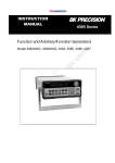
4.
-
PROGRAMMING AND INSTALLATION OF THE EP1000A:
Done with the PROGRAMMING and INSTALLATION menu, which allows the use
of other "sub-menus", as shown in the following chart:
Use the "local" or " remote" keyboard to gain access to these menus (see fig. 3 at the
beginning of the manual)
PROGRAMMING AND
INSTALLATION
Commissioning
prog.
Scale change
prog.
Top alarm and
integration
coeff. prog.
Serial link
prog – band rate
and slave No.
Change of particle
type and access code
Choice of
sensitivity: High
or Low
Entry of the new
scale
Choice of alarm
and of
integration time
Slave number
and band rate
Change of type and
access code
Choice of range
and estimate
entry
Are you sure?
Are you sure?
Are you sure?
Change of name of
the type chosen
Storing in
memory
Storing in
memory
Storing in
memory
Are you sure?
Are you sure?
AUTO-ZERO
Storing
in memory
Storing in
memory
Full auto-zero
Zero reset
Auto-zero start
menu
Warning
Are you sure?
Are you sure?
Storing in
memory
Auto-zero in
progress
89
4.1. PROGRAMMING AND COMMISSIONING
? As shown in the diagram on page 29, in the main "Programming and installation" menu.
? To gain access to this menu now, do the following:
NB: The industrial process is in operation.
Dust: SOAP
Measurement: x,x gr/Nm3
?
DISPLAY OF THE
MEASUREMENTS
ENTER OTHER RETURN
In normal operation:
Display of the current
measurement
Display of first menu
DATE AND TIME
ENTER OTHER RETURN
Display of second menu
Display of third menu "Programming
and installation" which will be used
PROG. & INSTALLATION
ENTER OTHER RETURN
Validate this menu
90
Request for access code
(1) Standard factory code: 1000 or code
modified by the user
To access the menu
enter your code ????
(1 )
The index below the figure indicates
the figure to be changed .
Using these 2 keys:
Display your code
Display of first menu
Validate the code
Display of "sub-menu":
"programming and commissioning"
COMMISSIONING PROG.
ENTER OTHER RETURN
Validate
Display of sensitivity choice "low" or "other"
Choice of sensitivity
* low sensitivity
Choice of sensitivity
High sensitivity
Validate your choice to suit the conditions
of the site to be monitored (2)
(2) Note: the sensitivity is chosen as a function of two parameters: the level of sunshine and the level of alternating signal.
In fact, it is necessary to have the maximum of usable signal while avoiding any saturation. It is possible to
do a first installation, and then to check the percentages of direct and alternating signal in the maintenance
menu.
For example:
- An installation in winter with 20% of direct component is very likely to be saturated in the summer. It
is necessary to go to low sensitivity.
- It is preferable to go to high sensitivity when there is a very high gain (64 x 128 x 256)
- If the EP1000A indicates “operation to exceed scale impossible”, it may be necessary to go to low
sensitivity.
91
Scale I Estimation
* 1 . 00 mg
? The star indicates the
value currently in
memory
N.B.: If the scale
changes, then the
EP1000A calculates
X0, XF, initial gains
and puts them in
memory.
? The star blinks
alternately with the
appearance of a black
square (1)
I 0 . 05 mg
You have the choice of
several scales between
1 mg and 10 g
Estimate of
current discharge
in smokestack
(1) this blinking black square shows the window which is currently modifiable
For example
Using this key:
Display the wanted scale.
By pressing once on this key to bring
the blinking black square into the
"ESTIMATION" window
Using this key:
Display estimate of current stack discharge
Validation of the new scale and
estimate parameters
ARE YOU SURE?
YES “ENTER” NO “MENU”
Request for confirmation of the new
programming
92
To validate “YES”
To validate “NO” and re-start, or to
keep the existing parameters
OR
PROG. & INSTALL
ENTER OTHER RETURN
Return to beginning of “Programming and
installation” menu
To use another menu
To return to normal operation and
display the current measurement.
OR
93
4.2 CHANGE OF SCALE
This sub-menu is used to go from one scale to another while keeping the measurement parameters
(xO and xF). It is therefore no longer necessary to repeat the calibration after this change of scale.
Warning: this type of change can only be done between adjacent scales (commissioning) and with
the same unit of measurement.
?
To gain access to this menu:
?
?
Dust: SOAP
Measurement: x,x gr/Nm3
In normal operation:
Display of current measurement
MEASUREMENT DISPLAY
ENTER OTHER RETURN
Display of 1st menu
DATE & TIME
ENTER OTHER RETURN
Display of 2nd menu
PROG. & INSTALLATION
ENTER OTHER RETURN
Display of 3rd menu
“Programming & installation” which will be used
Validate this menu
To access the menu
Enter your code ????
94
Request for access code
(1) Standard factory code: 1000 or code
95
To validate “YES”
OR
To validate “NO” and re-start, or to keep the
existing parameters
Return to the start of the
“Programming and installation” menu
PROG. & INSTALLATION
ENTER OTHER RETURN
To use another menu
OR
To return to normal operation and display of the
current measurement.
96
4.3 PROGRAMMING THE ALARM AND INTEGRATION TIME
Used to set the alarm threshold, as well as the integration5 time of the measurement (none, 5 sec,
30 sec, 1mn, 2 mn, 5 mn, 10 mn, 15 mn).
Example of display:
Alarm: I Integration
* X . X mg I * X sec
?
To gain access to this menu:
?
?
Dust: SOAP
Measurement: x,x gr/Nm3
MEASUREMENT DISPLAY
ENTER OTHER RETURN
In normal operation:
Display of current measurement
Display of 1st menu
DATE AND TIME
ENTER OTHER RETURN
Display of 2nd menu
PROG. AND INSTALLATION
ENTER OTHER RETURN
Display of 3rd menu
“Programming and installation” which
will be used
Validate this menu
5
an integrated measurement is one which is smoothed out. This smoothing will be calculated over an
interval which will match times chosen beforehand. This prevents the appearance of “peaks” of varying
size, due to sharp and sudden variations in signal amplitude.
97
To access the menu
Enter your code ????
Request for access code
(1) Standard factory code: 1000 or code
modified by the user
(1 )
The index below the figure indicates
the figure which will be changed.
Using these 2 keys:
Display your code
Validate the code
COMMISSIONING PROG.
ENTER OTHER RETURN
Display of 1st sub-menu
CHANGE OF SCALE
Display of 2nd sub-menu
ENTER OTHER RETURN
Display of 3rd sub-menu which will be used
ALARM & INTEGR. PROG
ENTER OTHER RETURN
Validate this sub-menu
98
Alarm: Integration
?xx mg
*x x sec
Blinking
black square
With this key:
Display the wanted alarm
With this key:
Display the wanted integration time
Validate this new programming
Request for confirmation of the new
programming
ARE YOU SURE?
YES “ENTER” NO “MENU”
To validate “YES”
OR
To validate “NO” and re-start or to keep
the existing parameters
Return to start of
“Programming and installation” menu
PROG. & INSTALLATION
ENTER OTHER RETURN
To use another menu
OR
To return to normal operation and display
of the current measurement.
99
4.4. SERIAL LINK PROGRAMMING
This is used to select the band rate of the serial link (1200, 2400, 4800, 9600 or 19200 bauds) and
the slave number for the J-Bus protocol, and to assign the slave number.
Example of display:
Band rate 9600 BAUDS
Slave number: 01
?
To gain access to this menu
?
?
Dust: SOAP
Measurement: x,x gr/Nm3
MEASUREMENT DISPLAY
ENTER OTHER RETURN
DATE AND TIME
ENTER OTHER RETURN
In normal operation:
Current measurement display
Display of 1st menu
Display of 2nd menu
PROG. & INSTALLATION
ENTER OTHER RETURN
Display of 3rd menu
“Programming & installation” which
will be used
Validate this menu
100
To access the menu
Enter your code ????
Request for access code
(1) Standard factory code: 1000 or code
modified by user
(1 )
The index below the number indicates the figure
which will be changed
Using these 2 keys:
Display your code
Validate the code
COMMISSIONING PROG.
ENTER OTHER RETURN
Display of 1st sub-menu
Press this key 3 times until the “Serial port
programming” menu appears
Display of the “Serial port” menu which
will be used
PROG. PORT SERIE , J BUS
ENTER AUTRE RETOUR
Validate
Blinking square
Band rate ? xxxx BAUDS
Slave number: xx
Using this key, change your band rate if
necessary (x Bauds)
The black square blinks in front of the slave
number
Now enter the slave number of your operation,
if necessary
101
Validate this programming
ARE YOU SURE?
YES “ENTER” NO “MENU”
Request for confirmation of the new
programming
To validate “YES”
OR
To validate “NO” and re-start, or to
keep the existing parameters
Return to the start of the
“Programming and installation” menu
PROG. & INSTALLATION
ENTER OTHER RETURN
To use the other menu
OR
To return to normal operation and to
display the current measurement
102
4.5. CHANGE OF PARTICLE TYPE AND OF THE ACCESS CODE
Note: This menu is used to go from one type of production or dust to another (10 types), and to
change the name of the process concerned.
?
To gain access to this menu:
?
Dust: SOAP
Measurement: x,x gr/Nm3
In normal operation:
Current measurement display
Display of 1st menu
MEASUREMENT DISPLAY
ENTER OTHER RETURN
DATE AND TIME
ENTER OTHER RETURN
Display of 2nd menu
Display of 3rd menu
“Programmation & installation” which
will be used
PROG. & INSTALLATION
ENTER OTHER RETURN
Validate this menu
103
Request for access code
(1) Standard factory code: 1000 or code
changed by the user
To access the menu
Enter your code ????
(1 )
The index below the number indicates
the figure to be changed
Using these 2 keys:
Display your code
Validate the code
COMMISSIONING PROG.
ENTER OTHER RETURN
Display of 1st sub-menu
Press this key 4 times until the “Change
particle and code type” menu appears
Display of “Change particle and code type”
menu which will be used
TYPE & CODE CHANGE
ENTER OTHER RETURN
Select. Type ?New
code
(1) Standard factory code: 1000 or code
modified by the user
Index
Index(1)
(1)
With this key: display the type number
104
Select. Type ?New code
TYPE X
?access xxxx
(index)
With these 2 keys: display your new access
code
&
Validate this new code
Option to assign a name to this "new"
particle type (8 figures and letters max)
You can change the header:
? TYPE X
Programming, if necessary, of this new
particle name
&
Validate this new programming
Request for confirmation of the new
programming
ARE YOU SURE?
YES - ENTER / NO-MENU
To validate “YES”
OR
To validate “NO” and re-start or to keep
the existing parmeters
Return to the start of the
“Programming & installation” menu
PROG. & INSTALLATION
ENTER OTHER RETURN
105
To use another menu
OR
To "return" to normal operation and
display the current measurement
106
4.6. CALIBRATION
When the above programming has been completed (1.4.1 to 1.4.5), the display now shows the
following alternatively with the current measurement.
Please perform
the calibration
For this, it is therefore necessary to use the calibration menu, the block diagram of which is
shown below:
CALIBRATION
Start of
sampling
End of
sampling
Entry of
results
Validation of
the start of
sampling
Validation of
the end of
sampling
Validation of
the results
Are you sure?
Are you sure?
Are you sure?
Storage in
memory
Storage in
memory
Storage in
memory
These various menus are used as follows:
Start of sampling
- To begin the storage of measurements for a given time, in accordance with
End of sampling
- To halt the storage of measurements
Entry of results
- To validate the actual result of the sampling using the keyboard, performed
the characteristics of the site.
by an official body – a comparison will be made between the measurements
taken by the EP1000A and the organisation concerned, and then the
appliance will effect an automatic correction if necessary.
107
?
To gain access to this main menu:
The index below the number indicates the
number which will be changed.
Please perform
the calibration
Using these 2 keys:
Display your access code
Appearance of the "Measurement
display" menu "
MEASUREMENT DISPLAY
ENTER OTHER RETURN
Press this key 4 times, until the
“Calibration” menu appears
Display of the "Calibration" menu which
will be used
CALIBRATION
ENTER OTHER RETURN
Validate this menu
Request for the access code
(1) Standard factory code: 1000 or code
modified by the user
To acces the menu
Enter your code ????
(1 )
The index below the number indicates the
figure which will be changed
Using these 2 keys:
Display your code
Validate the code
START OF SAMPLING:
ENTER OTHER RETURN
Validate the start of sampling
108
To start the sampling cycle:
‘ENTER’
To confirm the start of sampling (1)
ARE YOU SURE?
YES “ENTER” NO “MENU
To validate “YES”
OR
To validate “NO” and to keep the
existing parameters
Return to the start of the "Programming
and installation" menu "
CALIBRATION
ENTER OTHER RETURN
To return to normal operation and display of
the current measurement
Dust: -----x
Measurement: x x mg/Nm3
(1) When the "start of sampling" is confirmed, the EP1000A stores the measurements (storage in
memory) until the moment when "end of sampling” is validated.
(2) This time between "start and end of sampling" will be chosen according to the characteristics
of the site and the time necessary for the organisation to effect all of these various samples.
?
During this time:
- THE EP1000 continues, in parallel, to "work" normally.
- A sample, which will be sent to us later, is taken from the smokestack by
an approved organisation which will check exactly the weight of the
particles emitted (using a balance), in addition to various parameters such
as the flow, the temperature, the humidity, the dust, etc.
109
When the planned time between the "start and the end of sampling" has ended:
? Resume the procedure as before until the appearance of:
CALIBRATION
ENTER OTHER RETURN
Validate this menu again
To access this menu:
Enter your code xxxx (1)
(1) Standard factory code: 1000 or the
code modified by the user
&
With these keys: display your access code
Validate the code
END OF SAMPLING
ENTER OTHER RETURN
Validate the end of sampling
To end the sampling cycle:
‘ENTER’
To confirm the end of sampling (2)
Request for confirmation of the
new programme
ARE YOU SURE?
YES/ENTER - NO/MENU
110
To validate YES
OR
To validate “NO” and re-start, or to
keep the existing parameters
CALIBRATION
ENTER OTHER RETURN
Return to the start of the
"Programming and installation" menu
To use another menu
OR
To return to normal operation and to display the
current measurement
ENTRY OF THE SAMPLING RESULTS
Resume the
calibration
procedure as before until the appearance of:
ENTRY OF THE RESULTS
ENTER OTHER RETURN
Validation of the sampling results
entry menu
Done on - - / - from - - h to - - h - -: X.XX
Alternating with
The dust counter alternately displays the
measurements taken during the times and
on the dates shown
Average of dust counter
measurements: X.XX
111
Enter the sampling
results:X.XX
Enter the measurement given
by the approved body
AND
ARE YOU SURE?
YES ENTER NO MENU
- Validate this cal. measurement
4.7. READING THE VALUE SPECIFIED BY THE OPTICAL GAUGE
During the initial introduction to service, the optical gauge can be inserted and the value
indicated by the display noted. This operation repeated over time can be used to check that the
measurement does not drift.
Procedure
?
?
?
?
Undo the locking system of the appliance on its flange
Then pull the appliance open by rotating it
Insert the optical gauge as shown in figure 4 at the start of the instructions
Use the “optical gauge check” menu as follows:
112
Dust:……………..
Meadurement: xx mg/Nm3
Display of the current measurement,
in normal operation
Display of the 1st menu
MEASUREMENT DISPLAY
ENTER OTHER RETURN
Press this key 7 times until the
appearance of:
OPTICAL GAUGE CHECK
ENTER OTHER RETURN
Validate this menu
(1) Standard factory code: 1000 or
To access the menu:
Enter your code xxxx (1)
code modified by user
With these keys:
Display your access code
&
Validate this menu
Display of the signal read after
inserting the optical gauge
Mesurement of the signal on the
optical sensor: xx.x%
?
?
?
?
?
Allow the measurement to stabilise
Read and note the value read on the display of the appliance
Press twice on the MENU key to return
Remove the optical gauge and replace it carefully in its case
Close the appliance and do up the locking system
113
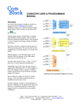
II. LIST AND FUNCTIONS OF THE OTHER MENUS
1.
BLOCK DIAGRAM OF THE MAIN EP 1000A MENUS
NORMAL OPERATION
DISPLAY OF
MEASUREM
ENTS
Display of
measurements
put in memory
DISPLAY OF THE
FAULT MENU
CONTROL
OF DATE
AND TIME
PROGRAMMING
AND
INSTALLATION
Menu for changing
the date and the
time
Access code
entry (1)
Are you sure?
See detailed
diagram in
section I.4
CALIBRATION
ACCESS TO
MAINTENANCE
AUTOZERO
Access code
entry (1)
Access code
entry (1)
List of parameters: intern.
temp., diode temp, meas.inst,
meas. Zero, initial & current
gain, laser power, etc.
(1) Standard factory access code: 1000 or code modified by the user
114
See detailed
diagram in
section I.4.6
Access code
entry (1)
4-20mA
CONTROL
MENU
OPTICAL
CHECK
MENU
Access code
entry (1)
Access code
entry (1)
Choice of current at
the 4-20mA output
Reading the value of
the optical gauge
2.
MEASUREMENT DISPLAY
This menu provides access to the measurements stored in memory.
?
To gain access to this menu:
Display of the current
measurement: example
Poussières:
Dusts: ----------savon
3
3
Measurement:
Mesure: xx mg/Nm
x x mg/Nm
MEASUREMENT DISPLAY
ENTER OTHER RETURN
Validate this menu
Inst: xx
Temp: xx
H/4: xx H: xx J: xx
Display of the current instantaneous
measurement (not including the integration
coefficient)
Display of the daily average
Display of the stored
measurements
Display of the daily average
Display of the hourly average
Display of the 15-minute average
Press this key twice to return to displaying the
current measurement.
Dust: ----------Measurement: x x mg/Nm3
115
3.
DATE AND TIME MANAGEMENT
This menu is used to display and alter the date and the time of the internal clock of the
EP1000A
?
To gain access to this menu
Dust: ---------Measurement: --- mg/Nm3
MEASUREMENT DISPLAY
ENTER OTHER RETURN
DATE AND TIME
ENTER OTHER RETURN
Validate this menu
Enter date and time
01. 12. 98 at 15 h 46
&
Display example
Use these keys to display the
wanted date and time
Validate
116
ARE YOU SURE?
YES-ENTER / NO-MENU
To validate YES
OR
To validate NO
DATE AND TIME
ENTER OTHER RETURN
To return to displaying the current
measurement.
Dust: ----------Measurement: --- mg/Nm3
117
4.
MAINTENANCE
This menu is used to consult the various operating parameters
Example of display (1st window):
TI 27.7 TD 2 0.1 pl 1.995
SH x128 - AN 0.59 MI 0.04
Example of display (2nd window):
i 3284 0 3295 x f 15380
c.cont 0% c.alt 11%
Meaning of the symbols used:
TI
Internal temperature
TD
Temperature of the laser diode (around 20°C)
pl
Emitted laser power (max: 2 mW and 1 Mw on average)
SH
High sensitivity
SB
Low sensitivity
Xxxx
gain (x1 to x 256)
+ or - or 0
ANX.XX
State of operation of the Peltier-effect module
+: heating
-: cooling
0: nothing
Analogue value of the input signal (between 0.5 and 5 V)
MI X.XX
Instantaneous measurement (according to scale)
i XXXX
"Interval" of the converter (measurement of the electrical zero, around
3273)
? XXXX
Full zero (after auto-zero)
X f xxxx
Value in "intervals" of the converter between to and bottom of scale
c.cont
c.alt xx%
XX% = the value of the direct component expressed as a %
The value of the alternating component expressed as a %
118
?
To gain access to this menu:
Dust: --------Measurement: -- mg/Nm3
MEASUREMENT DISPLAY
ENTER OTHER RETURN
Press this key 3 times until the
maintenance menu appears
MAINTENANCE
ENTER OTHER RETURN
To access the menu
Enter your code ????
&
Display the access code using these 2
keys
Validate your code
1st window
To display the 2nd window
119
2nd window
To exit from this menu
MAINTENANCE
ENTER OTHER RETURN
To return to displaying the current
measurement
Dust: --------Measurement: -- mg/Nm3
120
5.
AUTO-ZERO
Warning: this procedure is extremely important, and it is essential that it be
performed at the appropriate time, since it will have an impact on later operation.
? Main menu: this is used to start an auto-zero procedure (when the process is at a
halt)(1). The EP1000A calculates a full zero, and then corrects the XO XF automatically.
(1) Process shut down: This means that the ”industrial process” is halted, and that you have
expected and checked (by consulting the recording) during a certain time, that the emission
nevertheless delivered by the light now correspond to the correct moment for validation of
the auto-zero (cleaning or changing or purging the filters, purging the pipes upstream and
downstream of the filters or scrubbers, purging the smokestack, etc.).
Example: See figure 10 (at the beginning of the manual)
? Sub-menu: zero reset: this is used to reset the XO (bottom of scale) to the level of the
electrical zero.
WARNING: this menu erases previous auto-zero processes.
121
Example of display:
The appliance counts down (the time to do
the auto-zero), and this lasts for 1 minute.
Auto-zero in progress
Please wait: X X
Time displayed in seconds
?
To gain access to this menu:
Dust: --------Measurement: -- mg/Nm3
MEASUREMENT DISPLAY
ENTER OTHER RETURN
Press this key 5 times until the auto-zero
menu appears
AUTO-ZERO
ENTER OTHER RETURN
Validate this menu
To access the menu
Enter your code ???? (1)
(1) Standard Oldham code: 1000 or code
modified by the user
&
Use these 2 keys to display your access
code
122
Validate this code
FULL AUTO-ZERO
ENTER OTHER RETURN
Validate the auto-zero menu
TO DO THE AUTO-ZERO
CYCLE: ‘ENTER’
Alternate display of these 2 messages
Caution: check if smokestack
is shut down
Validate the start of the auto-zero process
ARE YOU SURE?
YES - ENTER / NO-MENU
To validate YES
OR
To validate NO
If “YES” validated
Auto-zeroing in progress
Please wait: __ __
Enter the remaining time (in seconds)
Auto-zeroing completed
Press any key
123
AUTO-ZERO
ENTER OTHER RETURN
To return to displaying the current measurement
DUST:- - - - - - - - - - - - Measurements
6.
CHECKING THE 4-20 mA
This menu uses the keyboard of the EP1000A to check the 4-20mA output . It is thus able to check
for the correct operation of the recorder, for example. Variation is possible from 0 to 24 mA
?
To gain access to this menu:
Dust: --------Measurement: -- mg/Nm3
MEASUREMENT DISPLAY
ENTER OTHER RETURN
Press this key 6 times until the "Checking the 420mA" menu appears
4-20ma CHECK MENU
ENTER OTHER RETURN
Validate this menu
124
To access the menu
Enter your code ???? (1)
&
(1) Standard Oldham code: 1000 or code
modified by the user
Use these 2 keys to display your access
code
Validate your code
Enter the number of mA at
the output: xx mA
To vary the output current at will from 0 to 24 mA
To exit from the menu
To return to displaying the current measurement
Dust: --------Measurement: -- mg/Nm3
125
7.
MISCELLANEOUS INFORMATION
Menu accessible by pressing key
It is then possible to view the following fault reports:
? laser diode temperature (15°C to 25°C)
? internal temperature (-30°C to + 70°C)
? laser diode power (2 mW max ? 0.05 mW)
? flow problem
? problem of saturation of the alternating component (> 65%)
? problem of saturation of the alternating component (> 87%)
? problem with commissioning into service
? problem with shift of the electrical zero (3269 to 3277 at gain)
?
By pressing
Note: If there is no fault, the appliance will show the following:
No fault to report
xxxxxxxxxENDxxxxxxxxx
NB: Exit from the menus is automatic after 15 minutes (if no operation is effected in that
time).
126
III. USING THE SORTIES AVAILABLE ON THE EP1000A
1.
FROM THE MAIN ANALOG BOARD
? The EP1000A has 2 relays, located on the main board:
- a Fault relay (fig. 5 ref. B)
- an Alarm relay (fig. 5 ref. A) which operates on failsafe
and their contacts are available on connector J5 (fig. 5 ref. C)
? The contacts are represented with the appliance switched off.
? The remote keypad will be connected to the socket provided for this purpose (fig. 9 ref.
17).
Note: The remote unit and the EP1000A will be connected by a 5-wire screened cable fitted at
each end with a connector.
? The measuring unit will be connected via connector J8 (fig. 5 ref. E)
- there are 2 possible versions: RS422 and RS485
- the choice is effected with the switch INV2 on the micro board (fig. 6, ref. A)
? The recorder will be connected via connector J6 (fig. 5 ref. F)
? The "FLOW DATA" signal will be available on connector J5 (fig. 5 ref. D (This is
controlled by the contact of the pressure switch).
2.
?
?
?
THE MICRO BOARD
The "MICRO" board is connected by a ribbon cable to the display board (output from
connector J2: fig. 6 ref. B)
The micro board is connected by a ribbon cable to the main analog board (output from
connector J1: fig. 6 ref. C)
The SUB.D "J4" connector (fig. 6 ref. D) is used for initialising the EP1000A in the
factory (EEPROM programming via RS232). Therefore to program the memory, it is
necessary to toggle the switch "INV1" (fig. 6 ref. E) to the “Factory” position.
Note: In the "factory" position of the switch "INV1", the RS485/422 outputs are cut off.
?
One has the choice of connecting an RS485 or RS422 acquisition unit by setting the switch
"INV2" (fig. 6 ref. A) to the desired position.
127
2.1. ABOUT THE RS485/422 SERIAL LINKS
(the data, the operation, the protocol, etc.)
?
The RS485 or 422 output can be used to connect 1 to 10 EP1000A appliances in a
network.
?
You can use the COM1000: D 813 408 software
?
Please consult the COM1000: D 813 421 user manual.
128
EP1000A
? STORAGE OF THE DATA, STARTING OPERATIONS
? THE COMMUNICATION PROTOCOL
? ORGANISATION AND OPERATION OF THE TRANSFER
TABLE
* STORAGE OF THE DATA
By means of the RS485/RS422 serial link, in communication with the EP1000A using the
JBUS or MODBUS protocol, it is possible to retrieve:
? the measurements in real time
? the faults
? the alarms
? the states
? the configuration words
? the measurement storage tables
STARTING OPERATIONS
? programming the date and time
? programming the alarm threshold and the integration coefficient
? changing the dust type
? launching an auto-zero
? changing the data storage interval
129
* COMMUNICATION PROTOCOL
? is used to read from and write to the authorised zones of the transfer table
? it is possible to identify 3 different zones
? the reading zone of the measurement storage areas (tables)
? the reading zone of the parameters, measurements, words, states, faults, etc.
? the zone for launching the various programming operations, auto-zero
processes, etc.: The write zone.
* ORGANISATION AND OPERATION OF THE TRANSFER
TABLE
- Measurement storage reading zone (tables)
The transfer table contains 19 tables:
? The program for the management of measurement storage is used to store
19720 measurements in memory.
? The storage interval is variable from 10 seconds to 1 hour.
? The measurement stored in the table is the mean of the measurements taken
during the storage interval.
? Because of this, the storage capacity is 19720 intervals.
The memory capacity: EXAMPLES
- For a measurement every 10 seconds:
38 HOURS
- For a measurement every hour:
570 DAYS!
130
Regarding the tables:
? When a table is full, you pass on to the next one.
? Each table contains 725 words.
? When the last table is full, you then go back to the first table.
? The first 720 words are used to store measurements
WARNING: The tables are not placed end to end. It is therefore necessary to know the
address of each table in the transfer table.
- Reading zone for the various parameters, measurements, status words,
faults, etc.
This reading zone is used to retrieve data for real-time monitoring of the operation of the
EP1000A.
In this part of the transfer table, you can find:
- various measurements and averages
- status words, faults, the date and time
- calculation, configuration, and designation parameters, etc.
- Write zone
This write zone is used to change certain parameters and to assign certain
operations.
Details of the write zone:
? change of dust type,
? modification of the name of the dust type,
? programming of the date and time,
? programming of the alarm,
? programming of the integration coefficient,
? programming of the storage interval,
? starting the auto-zero function,
? launching the start of calibration,
? launching the end of calibration,
? acknowledgement of the faults.
131
IV. MAINTENANCE
1.
?
PREVENTIVE AND PERIODIC MAINTENANCE
The EP1000A itself requires very little servicing, because of the following features:
- the use of a laser diode which has a life expectancy of 3 to 5 years (and is easy to
control). In addition, an electronic system continuously controls and regulates the
power emitted by the laser diode.
- synchronous detection is used to get over the background noise.
- it is fitted with a blowing and ventilation device which prevents the fouling of the
optics to a high degree and cools the heat sink of the laser diode.
- it is fitted with an air-flow sensor which sets off an alarm, and optionally has a device
for closure of the protective boot (thus preventing fouling of the optics in the event of
a blower or mains failure).
Nevertheless, its use on a smokestack and on industrial sites which are very dusty calls for
regular servicing.
Warning: the operations and adjustments described in this paragraph are reserved to
authorised personnel only.
?
In the EP1000A unit:
- a lithium battery (fig. 6 ref. F) backs up the memory of the micro board and has a life
expectancy of 5 years maximum. This battery must therefore be changed every 5 years
at least.
- check the slaved units controlled by the Alarm and Fault contacts and if necessary
change the soldered relays on the main analog board (fig. 5 ref. A and B).
- clean the parts in contact with the blown air and the dust from the smokestack. This
cleaning must be performed regularly, and in any event whenever there is a shut-down
of the process or the turbine due to a power failure or an air failure - see next
paragraph ("the various parts").
132
? THE VARIOUS PARTS:
- THE NOSE:
? Installation shut down
? Disconnect the hose coming from the turbine (fig. 8 ref. C)
? Remove the removable lower casing, after first removing the screws, to clean the
interior
? Re-fit the lower casing.
? Re-connect the air hose
? OPTICS:
?
?
?
?
Installation shut down
open the EP1000A by rotating it in relation to its fixings, after first operating the
lateral roses (fig. 8 ref. A)
clean the optics using a soft, damp cloth (fig. 8 ref. B)
clean the tube (fig. 8 ref. C) moving toward the smokestack.
? FIXING SYSTEM AND MATING FLANGE:
?
?
Installation shut down
before closing the EP1000A (by rotation): take advantage of the opportunity to
clean the conduit of the "fixing system/mating flange", going toward the smokestack
? TURBINE (air generator):
?
preventive maintenance on the turbine is limited to the cleaning or changing of the
air intake filter (Figure 7 ref. A), which is protected by a cover.
Note: this filter will become clogged at a rate which depends on the nature of the site.
? THE RECORDER:
?
?
?
For work by technicians on the types of recorder we use, please consult the manual
supplied with each appliance.
Periodic maintenance is limited to replacement of the pen head or felt and changing
the paper.
Nevertheless, you should regularly check for the correct operation of the recorder
by simulating a variation in the signal (0 to 24 mA) from the EP1000A unit, using
the "control of the 4-20 mA" menu (see section on "Use of the menus").
? THE ACQUISITION UNIT:
?
No servicing is necessary on this appliance. However, for all operations on the
acquisition unit, please consult the technical manual which comes with it.
133
? ASSISTANCE WITH SERVICING BY TECHNICIAN
?
Any person authorised to work on the EP1000A for the purpose of preventive or
remedial maintenance can use the "MAINTENANCE" menu in order to read up on
the various parameters in memory (see "use of the menus" and the "meaning of the
symbols" list).
?
The auto-zero: it is necessary to take advantage of a shut-down of the process in
order to perform an auto-zero on site. In particular, it is necessary to ensure that the
smokestack is fully shut down.
Use the AUTO-ZERO menu: see section on "use of the menus"
?
Calibration: it is necessary to carry out the calibration procedure at least one per
year.
?
Use the CALIBRATION menu for this: see section on "use of the menus".
Calibration consists of storing in memory the measurements taken by the EP1000A
for a time between the "start of sampling" and "end of sampling" times, and then
entering the data resulting from a sampling programme carried out by an official and
approved organisation. The EP1000A then does its corrections automatically.
Note: if the difference between the measurements of the EP1000A and the results of the
entered data is excessive, the EP1000A will display:
Calibration impossible
Values too different
It will then be necessary to check the installation in order to determine the origin of the
problem.
? THE LIGHT TRAP
Cleaning of the light trap should be carried out regularly, and in any event on the occasion of a
shut-down of the process or as a result of a breakdown.
The periodicity will depend on the nature of the site.
? THE PRESSURE DETECTOR (FIG 8 – REF C)
Cleaning of the pressure detector should be carried out regularly, and in any event on the
occasion of a shut-down of the process or as a result of a breakdown.
The periodicity will depend on the nature of the site.
?
?
?
?
?
?
Installation shut down,
Disconnect the hose coming from the turbine (fig. 8 ref. C),
Clean the interior of the input tube now accessible,
Remove the cover of the pressure detector (fig. 9 – ref. 23)
Clean, inside, the hoses and filters : replace them if necessary
Re-fit every part
134
2.
FAILURES - CAUSES AND REMEDIES
FAILURE
CAUSES
REMEDIES
- the EP1000A displays the fault:
"problem of saturation of the direct
component"
- the problem is due to interference
- take steps to eliminate these spurious
coming from the sun’s radiation, from sources from the area of the laser beam:
a street lamp on the site, etc.
move the offending light, do not place the
EP1000A too close to the exit from the
smokestack etc. and choose "low
sensitivity" in the programming and
installation menu
- the EP1000A displays the fault:
"problem of saturation of the
alternating component”.
- the problem is due to interference
coming from neon-type street lamps
or from another detection system on
the smokestack
- secure the detection appliances
(including the EP1000A) on the
smokestack in such a way as to avoid
interference between them.
- Move the neon light position on the site
if necessary.
- and choose "low sensitivity" in the
programming and installation menu.
- the EP1000A displays the fault:
"commissioning problem"
- commissioning into service has not
been successful
- repeat the commissioning procedure
using the "programming/installation"
menu, and check that the parameters
indicated are correct - choice of
sensitivity, scale, band rate etc.
- the EP1000A displays the fault:
"problem with shift of the electrical
zero "
- on start-up, the EP1000A does an
automatic electrical auto-zero during
the first 20 seconds, using its internal
microprocessor, but there can be
interference from neon lights or
powerful lamps.
- shut down the EP1000A and start it
again so that it repeats the electrical autozero process.
At the same time, eliminate all other
sources of interference. If the problem
persists, you will have to call an Oldham
technician
- impossible to store measurements
- the type of acquisition unit does not
with the acquisition unit connected to match the output of the EP1000A
the EP1000A
(RS485 or RS422)
- put the switch"INV2" (located on the
micro board) in the position which
corresponds to the unit.
- the connection between the unit and
the EP1000A is faulty.
- check the wiring at both ends of the
cable or check that the connector on the
EP1000A is inserted correctly.
- no message appears at the RS485 or
RS422 output of the EP1000A
- check that the switch "INV1" located on
the micro board is not in the “Factory”
position. If it is, switch it to the “Normal”
position. If the fault then persists, you will
have to get the analog board changed by
an Oldham technician
- the band rate is not the same in the
two parts.
- match the band rate of the 2 parts
- the slave number is not appropriate
135
- change the slave number on the
acquisition unit
FAILURE
CAUSES
- no deviation on the recorder when the - the "EP1000A/recorder" connection
EP1000A detects something.
is faulty
- the analog board of the EP1000A is
faulty (4-20 mA converter, for
example)
REMEDIES
- check the wiring at both ends or
check that the connector on the
EP1000A is correctly inserted.
Check the 4-20 mA output from the
EP1000A analog board and if
defective, get the analog board changed
by an Oldham technician
- the deviation of the recorder does not
match the EP1000A measurement.
- the recorder is incorrectly calibrated
- on the EP1000A, use the "CONTROL
OF THE 4-20 mA" menu and vary the
current to calibrate the recorder (refer
to the user manual of the recorder)
- the remote signalling fails when
"Fault" or a “dust” alarm occurs
- the electrical connection between the
EP1000A and the controlled items is
faulty.
- check the wiring between the
EP1000A and the controlled elements,
and also check that the connector on
the main EP1000A circuit is correctly
inserted
- the contacts of the fault and alarm
relays are defective.
- change the soldered relays on the
main EP1000A circuit
- the cable connection is faulty
- check the wiring, at both ends of the
cable, and also check that the
connector on the main circuit is
inserted correctly.
- the electronics of the unit are faulty
- change or repair the electronic circuit
of the remote unit
- the optics are dirty
- the power laser is faulty
- clean the optics
- check the power laser (maintenance
menu) and change the laser module if
necessary.
- the remote unit ceases to work: no
display and no remote control
- the signal displayed after insertion of
the optical gauge is no longer as it was
at the beginning
136
3.
LIST OF SPARE PARTS AND EXCHANGE PARTS
Optical gauge
E313039
Photoreceptor block
E313002
Photoreceptor element
6186724
Photoreceptor card
E451006
Analog board
E451003
250 mA fuse (analog board) 220 V version
6154693
Laser diode card
E451002
Laser module
E313001
Peltier module
E135001
Laser diode
6182167
Collimator
E133001
Display card
E451004
Micro board
E451001
Remote display board
E451005
Turbine filter
exchange cartridge
E136008
E136010
E136009
E136011
For recorder types 4101EC and 4101C
- Pre-folded paper (50 div.)
E113008
- Blue felt (path 1)
E113009
- Red felt pen head (path 2 on option)
E113010
- Green felt pen head (path 3 on option)
E113011
- violet felt pen head (path 4 on option)
E113012
- Black annotator felt
E113013
Turbine filter exchange
cartridge: large model
137
230 V Turbine
E 313 091
380 V Turbine
E 313 092
138
THE DEPENDABILITY OF A
PROFESSIONAL IN THE SAFETY FIELD
GUARANTY
Please refer to our sales conditions.
RELIABILITY
- CONTROLS
Your satisfaction is our primary concern. This means our equipment and our
technical departments must be reliable, and the quality of our production is
essential to achieve that reliability. Quality is ensured by extremely strict
verifications carried out during production, at the end of manufacture and
before shipment. (All shipped equipment is configured to meet your
requirements). These steps help to save time during equipment start-up and
avoid additional costs.
START-UP
Entrusting the start-up of your equipment to our expert technicians gives you
the guarantee of additional safety. Please see the list of our branches in
FRANCE, or our agents abroad.
FIELD
SERVICING
Our AFTER-SALES SERVICE technicians are ready to service your equipment
very quickly on your site. This performance is made possible by the efficient
network of our branches throughout FRANCE.
If you need field servicing, please call our After-Sales Service at the
following special phone number: 825 842 843
FACTORY
REPAIRS
For any problem which cannot be solved in the field, a team of SPECIALIZED
TECHNICIANS is on hand to ensure the immediate repair of your equipment
sent to our plant in ARRAS, France. In this way, OLDHAM S.A. undertakes
to keep the downtime for your equipment to a minimum.
139
MAINTENANCE
CONTRACT
REGULAR MAINTENANCE IS NEEDED to ensure that your equipment
meets the stipulated performance levels, as well as to guarantee the safety of
you and your personnel.
OLDHAM S.A. CAN offer you MAINTENANCE CONTRACTS with the
following terms:
? One or more visits a year, comprehensive or partial warranty.
? Renewable by tacit agreement.
? Including the adjustment of measuring units, the calibration of equipment
and the verification of servo-control systems.
TRAINING
OLDHAM S.A. has a fully-equipped TRAINING Department: a number of
engineers specialized as instructors, conference rooms, equipment available for
practical exercises, computer equipment, display equipment, etc…
You are thus assured that your personnel will receive all the TRAINING
REQUIRED to use our equipment and perform first-level maintenance. This
training can cover our entire product range.
OLDHAM S.A. organizes SCHEDULED TRAINING SESSIONS (1 week)
at the head office in ARRAS, France. Special training programmes can
however be set up at the head office or on your site.
QUALITY
With the assurance that we comply with ISO STANDARDS, our users can
have complete confidence in OLDHAM QUALITY.
ADVANTAGES
OLDHAM S.A. is represented all over France by full-scale branches with
secretarial services, sales personnel and technicians.
Efficient technical teams thanks to our ON-GOING TRAINING.
A COMPUTER-MANAGED STOCK OF SPARE PARTS.
OLDHAM S.A. uses all the modern means of communication, such as e-mail,
fax and Internet.
OLDHAM S.A. is always present at large trade events, i.e. regional, national
and international EXHIBITION.
140