1
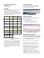
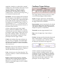
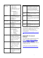
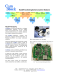
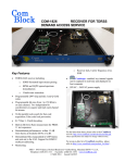
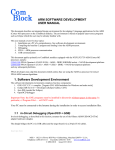
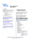
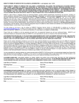
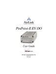
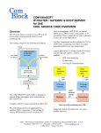
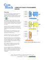
COMSCOPE USER & PROGRAMMING
MANUAL
Overview
New FPGA-based digital ComBlock modules are
equipped with the ComScope data capture
capability to help users visualize otherwise hidden
digital signals. These modules are identified with
Signal 1_3
Sample clock 1_3
source selection
The data of interest is captured at speeds up to the
FPGA processing speed. The user can select lower
sampling rates to expand capture over a longer time
period.
Internal triggers or user (manual) trigger can be
selected. Once the memory is full, data capture
stops until re-armed by the user.
Up to four data sources (Trace 1, Trace 2, Trace 3
and Trace 4) can be captured simultaneously.
Depending on the source type, the data storage is
organized as 4096 binary bits, 512 8-bit samples or
256 16-bit samples. Refer to specific ComBlock
module specifications for the definition of signals,
triggers and formats.
To Trace1
display
Signal 1_n
Sample clock 1_n
icon.
re-arm trigger
one-shot
trigger
Signal 2_1
Sample clock 2_1
Signal 2_2
Sample clock 2_2
Signal 2_3
Sample clock 2_3
Trace 2 4 Kbit Memory
Trace 2
Multiplexer
Internal digital signals, whether binary or digital
representation of analog signals, can be stored in
real-time within the internal memory, then exported
to a host computer for plotting, storage and further
processing.
256 samples x 16-bit
or
512 samples x 8-bit
or
4096 bits
Signal 2_m
Sample clock 2_m
source selection
256 samples x 16-bit
or
512 samples x 8-bit
or
4096 bits
re-arm trigger
one-shot
trigger
Signal T_1
Sample clock T_1
Signal T_2
Sample clock T_2
Signal T_3
Sample clock T_3
To Trace2
display
Trigger
Multiplexer
the
Signal 1_2
Sample clock 1_2
Trace 1 4 Kbit Memory
Trace 1
Multiplexer
Signal 1_1
Sample clock 1_1
Signal T_x
Sample clock T_x
03001802.dsf
user-trigger
source selection
ComScope Functional Block Diagram (2 traces)
Most ComScope settings are stored in volatile
memory. They are loaded automatically by the
ComBlock at power-up or reset.
Several ComScope windows, each pertaining to a
distinct ComBlock, can be opened at the same time.
However, it should be noted that, in most cases,
triggers cannot be synchronized across multiple
ComBlocks.
MSS • 18221 Flower Hill Way #A • Gaithersburg, Maryland 20879 • U.S.A.
Telephone: (240) 631-1111 Facsimile: (240) 631-1676
www.ComBlock.com
© MSS 2000-2005 Issued 8/11/2005
Starting ComScope
Graphical User Interface
User Manual
Start the ComBlock Control Center, enumerate the
ComBlocks, highlight the desired ComBlock and
click on the icon as shown below:
First Step
The very first step in using ComScope is to consult
the ComBlock specifications for definitions
regarding the trace signals and trigger signals. For
example, the COM-1028 FSK/MSK/GFSK/GMSK
modulator specifications include the following trace
and trigger signals definitions:
Trace 1 signals
Format
1: Data symbols
before Gaussian
filter
2: Data symbols
after Gaussian
filter
3: Frequency
modulator phase
4: Modulated
Signal I-channel
Trace 2 signals
1: Internal PRBS11 test sequence
2: Modulated
Signal Q-channel
Trigger Signal
1: Start of
internal PRBS11
test sequence
8-bit
signed
Nominal
sampling
rate
8 samples
/symbol
Buffer
length
(samples)
512
8-bit
signed
8 samples
/symbol
512
8-bit
signed
8 samples
/symbol
512
8-bit
signed
Format
fclk
(80 MHz)
Nominal
sampling
rate
1 sample /
bit
fclk
(80 MHz)
512
Binary
8-bit
signed
Format
Binary
Starting ComScope
ComScope window
The ComScope window is organized into three
distinct control sections:
(a) Trace settings on top
(b) Plot settings on the lower left
(c) Trigger settings on the lower right.
Capture
length
(samples)
4096
512
Example of Trace/Trigger signals definition
(COM-1028)
In this example, trace 1 can capture and display one
of four possible signals, all in 8-bit signed format.
512 samples of each signal are captured each time.
Likewise, trace 2 can capture one of two signals:
either 4096 samples of 1-bit binary data or 512
samples of 8-bit signed samples. Only one trigger
signal is offered.
ComScope window 3 control areas
ComScope Trace Settings
The Trace Settings section provides user control
over the following trace attributes:
Trace: select trace 1,2,3 or 4 to be configured.
Signal: each trace can capture one of several
multiplexed signals. Select the multiplexer source.
Representation: enter the precision for the selected
signal. Ranges from 1-bit binary to 16-bits. Also
indicates whether the binary representation is
unsigned or signed (2’s complement).
Sampling clock: select between ‘nominal’
sampling clock as described in the specifications
and the FPGA processing clock fclk. For example, in
a digital modulator, waveform signals are typically
2
sampled at 4 samples per symbol (their ‘nominal’
sampling rate), whereas binary data streams may be
typically sampled at 1 sample per bit (their
‘nominal’ sampling rate). When comparing
different traces, it is often clearer to select a
common clock (i.e. the FPGA processing clock fclk)
as it ensures the same time scale.
Decimation: select the sampling clock decimation.
The main purpose of decimation is to ‘stretch’ the
time scale, for example when a signal bandwidth is
much smaller than the sampling clock frequency.
Decimation can be selected by steps of 2 from 1:1
(no decimation) to 1:231 = 1: 2,147,483,648. One
should be aware that capture duration increases as
decimation factors increase.
All above controls are stored in non-volatile
memory within the ComBlock module. They are
recalled at power up. User changes are enacted by
pressing the “Apply Changes” button in the lower
part of the ComScope window. The changes are
applied the next time data is captured (i.e. after
pressing the “Re-arm Trigger” button).
Visible: this checkbox allows one to display one
trace at a time, or all together. The captured data
remains in memory while the trace is not visible.
The selection is volatile (i.e. returns to the default
value at power on).
ComScope Trigger Settings
The Trigger Settings section provides user control
over the following trigger-related attributes:
Signal: the trigger signal can be selected among
several signals through a multiplexer. Alternatively,
the trigger function can be disabled.
Representation: enter the precision for the selected
trigger signal. Ranges from 1-bit binary to 16-bits.
Also indicates whether the binary representation is
unsigned or signed (2’s complement).
Threshold: enter the trigger threshold / level.
Edge: enter the trigger edge / slope (rising or
falling).
Position: the trigger position determines how much
data is captured before a valid trigger condition
occurs. A vertical line at 0%, 10%, 50% or 90% of
the displayed time identifies the trigger time.
Plot style: select between small dots, big dots, lines
and big dots and lines. The selection is volatile (i.e.
returns to the default value at power on).
Color: select the trace color from the palette. The
selection is volatile (i.e. returns to the default value
at power on).
Export: export the trace samples to a decimal
format text file for further processing using other
applications, for example MS Excel (open or
Data|Get external data| import text file) or Matlab
(‘load’ command).
All above controls are stored in non-volatile
memory within the ComBlock module. They are
recalled at power up. User changes are enacted by
pressing the “Apply Changes” button in the lower
part of the ComScope window. The changes are
applied the next time data is captured (i.e. after
pressing the “Re-arm Trigger” button).
3
ComScope Plot Settings
Programming Interface
This section is intended for designers who want to
design their own graphical user interface. It can be
skipped by ComBlock Control Center users.
The display scale is automatically set when the
‘Auto scale’ checkbox is on. Otherwise, users can
specify the display scale by entering the Xmin, Xmax,
Ymin and Ymax values, then by clicking on the
Rescale button.
All ComScope-related commands are registermapped within the ComBlock. Registers 237
through 251 are reserved to this effect. All registers
are 8-bit wide. Register mapping is as follows:
Command
The time axis (X-axis) is relative to the trigger:
negative values represent samples captured before
the trigger condition occurred and vice-versa. The
time axis is expressed in ‘number of samples since
the trigger’ units.
All above controls are stored in non-volatile
memory within the ComBlock module. They are
recalled at power up.
Trace n signal
selection
Trace n
sampling clock
selection
ComScope Operations
The key difference between a conventional
oscilloscope and ComScope is that ComScope
capture and display is always started manually.
There is no automatic refresh.
Re-arm Trigger: orders the ComBlock to capture a
new batch of samples. If the capture is complete
within approximately one second, the captured data
is automatically displayed. If capture is incomplete
or if the trigger condition did not yet occur, the user
is invited to press either the ‘Force Trigger’ button
(if trigger did not occur) and/or the ‘Plot button’ (if
the capture is too slow).
Trace n
sampling clock
decimation
Definition
0 = disable trace n.
1-127 = signal selection. ComBlockspecific definition. See specifications.
Non-volatile storage.
n = 1:
REG240 bits 6-0
n = 2:
REG242 bits 6-0
n = 3:
REG244 bits 6-0
n = 4:
REG246 bits 6-0
0 = use nominal sampling clock as
described in the specific ComBlock
specifications.
1 = use the ComBlock fclk processing
clock (typically 40MHz or 80 MHz or
120 MHz) as sampling clock. This
allows to compare multiple signals on
the same time scale.
In either case, the sampling clock can
be further decimated to stretch the time
scale. (see decimation control below)
n = 1:
REG240 bit 7
n = 2:
REG242 bit 7
n = 3:
REG244 bit 7
n = 4:
REG246 bit 7
Decimate selected signal sampling clock
by 2n, where n = 0 through 31.
0 means no decimation.
Non-volatile storage.
n = 1:
REG241 bits 4-0
n = 2:
REG243 bits 4-0
n = 3:
REG245 bits 4-0
n = 4:
REG247 bits 4-0
Force Trigger: manual substitute to the automatic
trigger condition. Must be used when the trigger is
disabled.
Plot: ask the ComBlock to provide the captured
data. Keep pressing this button until the capture is
complete.
4
Trigger position with
respect to trace n
capture window
Trigger signal
selection
Signed/Unsigned
trigger threshold
Trigger edge
Trigger threshold
Force trigger
Trigger re-arm
Capture resume
0 = trigger set at 0%
1 = trigger set at 10%
2 = trigger set at 50%
3 = trigger set at 90%
Note: All trigger positions must be
identical. Use same value for all
traces.
Non-volatile storage.
n = 1:
REG241 bits 7-5
n = 2:
REG243 bits 7-5
n = 3:
REG245 bits 7-5
n = 4:
REG247 bits 7-5
0 = trigger is off
1-63 = internal signal selection.
ComBlock-specific definition. See
specifications.
Non-volatile storage.
REG248 bits 5-0
0 = trigger threshold is unsigned
1 = trigger threshold is signed
Non-volatile storage.
REG248 bits 6
0 = falling edge
1 = rising edge
Non-volatile storage.
REG248 bit 7
When the selected trigger signal is
an m-bit word, then the trigger
threshold is given by:
m =1:
REG249 bit 0
m =2:
REG249 bits 1-0
m =4:
REG249 bits 3-0
m =8:
REG249
m =10: 4 x REG249
m =16: 256 x REG249
One-shot trigger originated by the
user. Write a ‘1’ once to force the
manual trigger. Overrules the
trigger signal selection. The trigger
must have been re-armed before a
force trigger may take place.
Volatile.
REG250 bit 0
One-shot command originated by
the user. Writing a ‘1’ once will
force the traces in use to switch
state from “Capture in progress,
pre-trigger” to “Capture in
progress, waiting for trigger”.
Volatile.
REG250 bit 1
One-shot command originated by
the user. Writing a ‘1’ once starts
the capturing again after a capture
was completed.
REG250 bit 2
Monitoring
Read data
Capture in
Progress
Trigger
Found
Start Capture
Toggle
Trigger Rearm Toggle
Definition
ComScope trace data can be exported out
of the ComBlock by reading at address
250. Stored data is read in sequence,
starting at the initial address defined in
REG237/238/239, and subsequently
autoincremented after byte read at address
250.
REG250
0 = capture ceased
1 = at least one trace is capturing
REG251 bit 0
0 = trigger not found
1 = trigger found
This bit is cleared (set to 0) upon resuming
capture (see Read/Write register 250, bit 2).
REG251 bit 1
This bit toggles every time capture is
resumed (see Read/Write register 250, bit
2).
REG251 bit 2
This bit toggles every the trigger is rearmed (see Read/Write register 250, bit 1).
REG251 bit 3
The general M&C commands “Set Register SRG”
and “Set Register Temporary SRT” are used to send
commands to the ComBlock registers. See
reference document “ComBlock Monitoring &
Control Reference”
www.comblock.com/download/M&C_reference.pd
f
FPGA/VHDL Development
Platforms
The ComBlock family of rapid prototyping modules
includes several FPGA/VHDL development
platforms (COM-1000, COM-1100, COM-1200,
COM-1300, COM-1400, COM-8000) based on
Xilinx FPGAs. VHDL code templates for these
development platforms are being updated with basic
ComScope source code.
Template source code can be downloaded from
www.comblock.com/download/com1000_002.zip
5