1
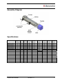
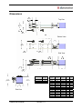
®
TM
MICROSTAGE SERIES
Micro Positioning Stage System
USM28
USER’S MANUAL
USM28 User's Manual
Revision 1.4
©2010 USAutomation, Inc.
All rights reserved
USAutomation® MicrostageTM Series User's Manual
This manual, as well as the software described in it, is furnished under license and may be used
or copied only in accordance with the terms of such license. The content of this manual is
furnished for informational use only, is subject to change without notice and should not be
construed as a commitment by USAutomation. USAutomation assumes no responsibility or
liability for any errors or inaccuracies that may appear herein.
Except as permitted by such license, no part of this publication may be reproduced, stored in a
retrieval system or transmitted, in any form or by any means, electronic, mechanical, recording,
or otherwise, without the prior written permission of USAutomation.
USAutomation, Inc.
23011 Moulton Parkway
Suite J2
Laguna Hills, CA 92653
(949) 588-0513
(949) 588-8761 fax
www.usautomation.com
USM28 User's Manual
Revision 1.4
2
Revision Notes
1.0
Original release
1.1
2/23/09
1.2
10/2/09
1.3
5/26/10
1.4
10/26/10
USM28 User's Manual
New logo
Updated limit switch sensor part number
Updated part number scheme
Added moment loading
Revision 1.4
3
Contents
Revision Notes .............................................................................................................................. 3
Using This Manual ........................................................................................................................ 5
Product Returns ............................................................................................................................ 5
Unpacking and Handling ............................................................................................................... 5
Assembly Diagram ........................................................................................................................ 6
Specifications ................................................................................................................................ 6
Dimensions ................................................................................................................................... 7
Moment Loading ........................................................................................................................... 8
Part Number Configuration ........................................................................................................... 8
Mounting the USM28 .................................................................................................................... 9
Mounting a Load to the USM28 .................................................................................................... 9
Step Motor Information ................................................................................................................. 9
Electrical Rating Information ..................................................................................................... 9
Electrical Schematic .................................................................................................................. 9
Switching Sequence ................................................................................................................ 10
Limit Switch Information .............................................................................................................. 10
Dimensions .............................................................................................................................. 10
Wiring ...................................................................................................................................... 11
USM28 User's Manual
Revision 1.4
4
Using This Manual
The Microstage Series are small packaged positioning stage systems which normally includes a
step motor and coupling. The USM28 has a cross sectional size of 28mm x 28mm, travel
lengths up to 205mm, an anti-backlash TFE coated leadscrew and a square rail supported
carriage for mounting a load.
This manual provides the basic information necessary to unpack, set up, and configure the
USM28. If additional information is required beyond what is presented here, please refer to the
Support section of our website or contact USAutomation Applications Engineering.
Product Returns
All returns for warranty or out-of-warranty repairs must first receive an RMA (Return Material
Authorization) number. Please contact USAutomation Customer Service Department with
information about the return and an RMA number will be issued if warranted.
Products returned to the factory will be examined and tested for failure mode and cause.
USAutomation Customer Service will contact the customer with the repair cost if the required
repair is out of warranty.
Unpacking and Handling
Carefully remove the USM28 from its shipping box and inspect the unit for any evidence of
shipping damage. Report any damage immediately to USAutomation. Please save the shipping
box for damage inspection or its use in returning product if necessary.
Please observe the following guidelines for handling and mounting of your USM28:
•
•
•
•
Do not drop the stage on any hard surface or subject it to any impact loads. Dropping
the stage or other impact loads may result in bearing damage or misalignment.
Do not drill holes into the stage. Drilling holes into the stage can generate particles and
machining forces that may affect the operation of the stage. USAutomation can supply
the USM28 with modifications to your drawing. Please contact the factory for a quote.
Do not expose the USM28 to mist, spray or submersion in liquids.
Do not disassemble the USM28. Unauthorized adjustments may alter the specifications
and void the product warranty.
USM28 User's Manual
Revision 1.4
5
Assembly Diagram
Specifications
USM28T-010-XX-X
Maximum
Dynamic
Load (lbs)
5
Travel
(MM)
10
Lead
(in)
.100
Accuracy
(in/in)
.0006
Max Linear
Speed
(in/sec)
Leadscrew
Efficiency
69
Coeff of
Friction
(Constant)
.09
Drag
Torque
(in/oz)
< .5
Motor
Torque
(oz in)
8.3
USM28T-025-XX-X
5
25
.100
.0006
2.5
2.5
69
.09
< .5
8.3
USM28T-040-XX-X
5
40
.100
USM28T-055-XX-X
5
55
.100
.0006
.0006
2.5
69
.09
< .5
8.3
2.5
69
.09
< .5
USM28T-070-XX-X
5
70
.100
8.3
.0006
2.5
69
.09
< .5
USM28T-085-XX-X
5
85
8.3
.100
.0006
2.5
69
.09
< .5
8.3
USM28T-100-XX-X
USM28T-115-XX-X
5
5
100
.100
.0006
2.5
69
.09
< .5
8.3
115
.100
.0006
2.5
69
.09
< .5
USM28T-130-XX-X
8.3
5
130
.100
.0006
2.5
69
.09
< .5
8.3
USM28T-145-XX-X
5
145
.100
.0006
2.5
69
.09
< .5
8.3
USM28T-160-XX-X
5
160
.100
.0006
2.5
69
.09
< .5
8.3
USM28T-175-XX-X
5
175
.100
.0006
2.5
69
.09
< .5
8.3
USM28T-190-XX-X
5
190
.100
.0006
2.5
69
.09
< .5
8.3
USM28T-205-XX-X
5
205
.100
.0006
2.5
69
.09
< .5
8.3
Part Number
USM28 User's Manual
Revision 1.4
6
Dimensions
Top View
Bottom View
Side View
Motor
Dim M
in (mm)
Travel
in (mm)
Dim A
in (mm)
USS11T2102-4S
1.25 (31.8)
0.39 (10)
2.05 (52)
USS11T2202-4S
1.75 (44.5)
0.98 (25)
2.64 (67)
USS11T2302-4S
2.00 (50.8)
1.57 40)
End View
USM28 User's Manual
Revision 1.4
Dim B
in (mm)
Qty
C
Qty
D
.325 (8.3)
4
1
.687 (17.2)
4
1
3.23 (82)
.325 (8.3)
6
2
2.17 (55)
3.82 (97)
.687 (17.4)
6
2
2.76 (70)
4.41 (112)
.325 (8.3)
8
3
3.35 (85)
5.00 (127)
.325 (8.3)
10
4
3.94 (100)
5.59 (142)
.687 (17.4)
10
4
4.53 (115)
6.18 (157)
.325 (8.3)
12
5
5.12 (130)
6.77 (172)
.687 (17.4)
12
5
5.71 (145)
7.36 (187)
.325 (8.3)
14
6
6.30 (160)
7.96 (202)
.687 (17.4)
14
6
6.89 (175)
8.55 (217)
.325 (8.3)
16
7
7.48 (190)
9.14 (232)
.325 (8.3)
18
8
8.07 (205)
9.73 (247)
.687 (17.4)
18
8
7
Moment Loading
Part Number Configuration
The part number for the Microstage USM28 is determined as follows:
USM28 User's Manual
Revision 1.4
8
Mounting the USM28
Threaded mounting holes are located on the underside of the housing. The holes for the
USM28 are 4-40 UNC with a .125” depth. Generally it is best to have through holes matching
the pattern of the mounting holes in the surface to which it is to be secured such that 4-40
screws pass through the surface and into the threads in the housing. Review page 7 of this
manual for the location and number of holes based on the length of the Microstage. Care
should be taken to not let the mounting screws penetrate the carriage more than the .125” depth
or there may be interference with moving components in the stage.
Mounting a Load to the USM28
Motor
USS11T2102-4S
Bipolar
Torque
(oz in)
8.3
Series
Current
(A)
0.67
Series
Inductance
(mH)
4.0
Rotor
Inertia
2
(oz in sec )
.00013
Shaft
Diameter
(in)
.197
# of
Leads
Weight
(lbs)
Length
(in)
4
.24
1.250
Four (4) 2-56 UNC with .222” depth are located on the top of the carriage for mounting a load to
the USM28 (see the Dimensions section). Care should be taken not to exceed this maximum
depth so as to not interfere with other components of the carriage assembly.
Step Motor Information
The standard motor which comes with the USM28 is a 1.8° hybrid step motor with four leads.
This motor can be connected to any bipolar step motor driver/controller. Full torque will be
available from the motor when used with a drive which has a rated output with at least .67 amps
per phase. Here are the ratings for the standard Microstage USM28 step motor:
Electrical Rating Information
Other motors are available from USAutomation including longer stack length step motors,
motors with built in drive/controllers, and brushless motors. Please contact the factory for more
information.
Electrical Schematic
USM28 User's Manual
Revision 1.4
9
Switching Sequence
Step 1
Step 2
Step 3
Step 4
Black
+
+
Orange
+
+
-
Red
+
+
-
Yellow
+
+
Limit Switch Information
If your Microstage has the optional limit switches they will be mounted on the side of the stage
housing and are adjustable. Depending on the driver used the limit switches can be configured
as end-of-travel limits and/or one of them can be configured as a home switch.
The limits are SUNX model PM-F24, an infrared U-channel switch which is interrupted by a flag
mounted to the moving carriage of the Microstage. The output of the switches is NPN opencollector with both Light-ON and Dark-ON modes. A 1.0 meter cable is supplied to make the
connections to the driver.
Dimensions
USM28 User's Manual
Revision 1.4
10
Wiring
Generally, Output 2 will be used because the switch output will then go ON when the flag
interrupts the switch. In addition, for safety the switch will appear triggered (shutting down
travel) if there is a break in the wiring to the switch.
If further more detailed information is required for the sensor, please refer to this URL:
http://www.sunx-ramco.com/SunxPDFFiles/PM.pdf .
USM28 User's Manual
Revision 1.4
11