1
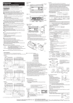
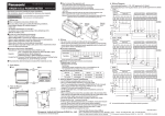
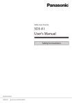
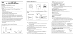
<Label position>
INSTRUCTION MANUAL
MJE-HLG1(06) No.0042-42V
WARNING
●● This product is intended to detect the objects and does not have the control function to ensure safety such as accident prevention.
●● Do not use the product as a sensing device to protect human body.
●● Please use the products that comply with local laws and standards for human
body protection specified by e.g., OSHA, ANSI and IEC.
●● Install a fail-safe device when the product is used for the purpose that has a possibility of physical injury or serious extended damage.
●● D
o not use the product in the atmosphere of flammable gas, to prevent explosion.
●● Install the product so the laser beam comes higher or lower than eye level in order
not to watch the beam directly during operation. Laser safety distance (Nominal
Ocular Hazard Distance: NOHD) is approx. 0.4 m. The laser beam must be terminated at the end of its path by a diffuse reflector or an absorber.
●● Please contact Panasonic Industrial Devices SUNX if the system breaks down. It
is not equipped with a function that stops laser radiation automatically during disassembling the sensor head. The users therefore may be exposed to laser beam
in disassembling the sensor head.
●● D
o not use the system in the manner other than specified in this Instruction Manual.
3 I/O BLOCK AND NOMENCLATURE
2
1
3
4
5
8
6
BEFORE USE
●● Before using the product, check the sensor head model and contents of packing.
●● Sensor head model
Check the model name of product at the top of
sensor head.
7
9
10
●● Packing
Check that all of the following components are
included in the package.
• 1 sensor head unit
• 2 Instruction manual
(Japanese / English: 1, Chinese / Korean: 1)
• Laser warning labels (one set)
1 OVERVIEW
●● This product is a compact laser displacement sensor incorporating a digital display and controller functions.
●● The standard type has three outputs plus analog outputs (current and voltage outputs), thus supporting multi input signals.
●● The high-function type incorporates serial communications functions in addition to
the specifications of the standard type, and can be easily controlled by host devices.
●● One out of five measurement distances can be selected for each type that support
both NPN and PNP outputs.
2 CAUTIONS ON HANDLING LASER LIGHT
●● In order to prevent the accidents by laser product and protect the users, IEC, JIS,
GB and FDA establish the following standards respectively.
IEC : IEC 60825-1-2007 (EN 60825-1-2007)
JIS : JIS C 6802-2005
GB : GB 7247.1-2012
FDA: PART 1040(PERFORMANCE STANDARDS FOR LIGHT-EMITTING
PRODUCTS)
These standards classifies laser products according to the level of hazard and
provide the safety measures for respective classes.
●● Laser hazardous class
Classification according to IEC 60825-1-2007(JIS C 6802-2005)
Class
Model
Class 2
HL-G1□-A-C5
HL-G1□-S-J
●● WARNING label
<English>
11
1
2
3
4
Function
A(V)
Analog voltage output
Wiring color
AGND
Analog ground
Shield
single
conductor
Black
Shield
single
conductor
Gray
A(I)
Analog current output
AGND
Analog ground
OUT1
Judgment output 1
Black
OUT2
Judgment output 2
White
OUT3
Judgment output 3 or alarm output
Gray
TM
Timing input
Pink
MI
Zero-set, Reset, Memory change,
Teaching, Save, and Laser control
inputs
Violet
NP
NPN / PNP type switching input
+SD
Transmission data
-SD
Transmission data
Pink / Violet
Twisted
-pair wire
+RD
Reception data
-RD
Reception data
SG
Signal ground
Shield
+V
24 VDC input for power supply
Brown
0V
Power supply ground
Blue
Twisted
-pair wire
Green
Sky Blue
Orange
Yellow
9 [DOWN] Key
10 Emitter
11 Receiver
OUT13 Indicator (OUT3)
[ENTER] Key
Digital Display
[UP] Key
4 SPECIFICATIONS
Model
No.
Standard type
HL-G103-A-C5
HL-G105-A-C5
HL-G108-A-C5
HL-G112-A-C5
HL-G125-A-C5
High-function type
HL-G103-S-J
HL-G105-S-J
HL-G108-S-J
HL-G112-S-J
HL-G125-S-J
Measurement method
Diffuse reflection
Measurement center distance
30mm
50mm
85mm
120mm
250mm
Measurement method
±4mm
±10mm
±20mm
±60mm
±150mm
Beam source
Red semiconductor laser Class 2 (JIS / IEC / GB / FDA laser notice No. 50)
Max output: 1mW, Emission peak wavelength: 655nm
Beam diameter (Note 2)
0.1 × 0.1mm
0.5 × 1mm
0.5μm
1.5μm
Beam receiving element
Resolution
Linearity
Temperature characteristics
Supply voltage
Current consumption
Sampling cycle
Analog
output
0.75 × 1.25mm
1.0 × 1.5mm
1.75 × 3.5mm
CMOS image sensor
2.5μm
8μm
±0.1%F.S.
20μm
±0.3%F.S.
±0.08%F.S./°C
24V DC ±10% including ripple 0.5V (P - P)
100 mA max.
200μs, 500μs, 1ms, 2ms
Voltage
Output range: 0 to 10.5 V (normal), 11 V (at alarm)
Output impedance: 100Ω
Current
Output range: 3.2 to 20.8 mA (normal), 21.6 mA (at alarm)
Load impedance: 300Ω max.
Judgment output or alarm output (switchable)
NPN open-collector transistor / PNP open-collector transistor (switchable)
OUT1
OUT2
OUT3
<Japanese>
Short-circuit protection
NP switching input
<Settings for NPN>
• Peak in-flow current: 50mA
• Applied voltage: 3 to 24V DC
(between output and 0V)
• Residual voltage: 2V max.
(at in-flow current of 50mA)
• Leakage current: 0.1mA or less
<Settings for PNP>
• Peak in-flow current: 50mA
• Residual voltage: 2.8V max.
(at in-flow current of 50mA)
• Leakage current: 0.1mA or less
Open when the output is ON.
Incorporated (Auto-reset)
At 0V: NPN open-collector output
At supply voltage of 24V DC: PNP open-collector output
Timing input
NPN operation: ON when connecting or connected to 0V (depending on settings)
PNP operation: ON when connecting or connected to positive terminal of external
power supply (depending on settings)
Multiple input
Zero set, reset, Memory change, Teaching, Save, or Laser control depending on input time.
NPN operation: Depending on time to connect 0 V
PNP operation: Depending on time to connect positive terminal of external power supply
Communications interface
(high-function type)
RS-422 or RS-485
Baud rate: 9,600 / 19,200 / 38,400 / 115,200 / 230,400 / 460,800 / 921,600 bps
Data length: 8 bits, stop bit length: 1 bit, parity check: none, BCC: yes, end code: CR
Indicator
<Korean>
5
6
7
8
Laser Indicator (LASER)
Alarm Indicator (ALARM)
OUT1 Indicator (OUT1)
OUT2 Indicator (OUT2)
Description of hazardous evaluation
Visible beam, low power. Blink response of eye affords protection.
Name
* No SD/RD terminals are prepared for HL-G1□-A-C5 standard types.
Output operation
<Chinese>
Analog Output Lines
Thank you for purchasing the product of Panasonic Industrial Devices SUNX Co.,
Ltd. Be sure to read this manual before use in order to ensure the safe and proper
operation of this product. Keep this manual at hand for your reference after reading it
through.
Download the HL-G1 Series User's Manual (PDF) from Panasonic Industrial Devices
SUNX Co., Ltd. (http://panasonic.net/id/pidsx/global). Be sure to refer to the User's
Manual for information in detail before making settings in the control panel of the
sensor head.
I/O Terminal Block
0631996
Compact Laser Displacement Sensor
Standard type
High-function type
HL-G1□-A-C5
HL-G1□-S-J
Laser radiation indicator
Green LED ON at laser radiation
Alarm indicator
Orange LED ON when measurement is disabled due to insufficient amount of light
Output indicator
Yellow LED (No. of indicators: 3) ON at output
Digital display
Protective structure
Pollution degree
Red LED for sign and 5-digit display
IP67 (except connector)
2
Insulation resistance
20MΩ min. at 250V DC megger (between charged parts and casing)
Dielectric Withstand
1,000V AC for 1 min. (between charged parts and casing)
Vibration resistance
Endurance: 10 to 55 Hz (at 1-minute cycle), 1.5 mm double-amplitude
Vibration resistance
Ambient illumination (Note 3)
500m/s2 three times each in X, Y, and Z directions
3,000ℓx max. (illumination level of light receiving surface under incandescent light)
Ambient temperature
Ambient humidity
Ambient Height
Material
35 to 85%RH, At storage: 35 to 85%RH
2,000m or less
6 I/O CIRCUIT
●● NPN Type
Casing: PBT, Front cover: Acrylic, Cable: PVC
Cable length
Lead wire color
Standard type: 5m; high-function type: 0.5m
Cable extension
Mass
-10 to 45°C (No dew condensation or icing allowed), At storage: -20 to 60°C
High-function type: extendable to 20 m with an optional extension cable (sold separately).
Standard type
Approx. 70g (without cable), approx. 320g (including cable), and approx. 380g (with packing)
High-function type
Approx. 70g (without cable), approx. 110g (including cable), and approx. 160g (with packing)
Applicable standards
(Brown) +V
(Black) Output 1: OUT1
50mA max.
Conforming to EMC Directive
Notes:1)The following measurement conditions are applied unless otherwise specified; power voltage: 24V DC, ambient temperature: 20°C, sampling cycle: 500μs, average number of sampling times: 1,024 times, measurement center distance, and measurement object: white ceramic.
2)The diameter is the size of the object at the measurement center distance and determined by 1/e2 (approximately 13.5%) of the center beam intensity. The reflectance around the detecting point may be higher than at
the point due to leak light outside the specified area, and this may affect the measurement value.
3)Variance is ±0.1%F.S. or less depending on the ambient illuminance.
Connections
●● Be sure to turn OFF the power supply before connecting or disconnecting any
connectors.
●● When connecting or disconnecting the connectors, be sure to hold the connector
area not to apply extra force to the cable.
●● Be careful not to touch terminals or to let foreign objects get in the connector after
disconnecting connectors.
●● Be careful not to apply force to around the connector of sensor head cable and
extension cable. Do not bend the cables near connectors, which causes disconnection of the cable.
●● When moving the sensor head during operation, install not to bend the cable during movement. Use replaceable extensions cable where the cable needs to be
bent.
50mA max.
(Gray) Output 3: OUT3
50mA max.
Main circuit
5 CAUTIONS
(White) Output 2: OUT2
Load
Load
External
power supply
3 to 24 VDC
Load
Main power
supply
24 VDC ± 10%
Ripple 0.5 V
(peak-to-peak)
included
(Pink / Purple) NPN / PNP type switching input
3.3V
(Pink) Timing Input: TM
3.3V
(Purple) Multiple input: MI
*1
(Blue) 0V
Sensor head
internal circuit
External connection example
*1
Non-voltage contact
Wiring
Warming Up
●● Allow at least 30 minutes of warming up after turning on the power to ensure the
performance of the product.
IN
Refer to the HL-G1 Series User's Manual for RS-422
/ 485 wiring.
Lead wire color
(Brown) +V
(Black) Output 1: OUT1
50mA max.
(White) Output 2: OUT2
50mA max.
(Gray) Output 3: OUT3
50mA max.
Load
Load
Load
Main power
supply
24 VDC ± 10%
Ripple 0.5 V
(peak-to-peak)
included
(Pink / Purple) NPN / PNP
type switching input
*1
Environment
●● Mount the sensor head to an aluminum or steel plate with a minimum surface
area of 200cm2 if the ambient temperature is 40°C or higher. In the case of installing two or more sensor heads in parallel, mount each sensor head to an aluminum or steel plate with a minimum surface area of 200cm2 and make sure that the
ambient temperature does not exceed 40°C.
●● The life of the semiconductor laser depends on the ambient temperature during
use. When using the product near a heat source, take measures to keep the ambient temperature of the sensor head as lower as possible. Mount the sensor on a
device having good heat radiation because the sensor itself also generates heat.
●● Keep the emitter surface and the receiver surface clean, not to attach light refractors such as water, oil and fingerprints, or light blockers such as dust and dirt.
When cleaning these parts, wipe them off using a soft lint-free cloth or lens cleaning paper.
●● Install the sensor head at where extraneous light (such as sunlight or light which
has the same wavelength as laser beam) do not enter the receiver. If high accuracy is required, install a light shield plate or the like on the sensor head.
●● The sensor head has protection against immersion, while the connectors are not
structurally dustproof, waterproof, or corrosion-resistant. Do not use the product
underwater or in the rain.
●● Do not use the product in dusty places or that exposed to flammable or corrosive
gases, droplet, direct sunlight, severe vibration or impact.
0V
●● PNP Type
Main circuit
●● Do not roll up the sensor cable (bundle in parallel) with other wirings. Keep it at
least 100mm away from other wires. Cables should be separated from high voltage and power circuit lines. If it is unavoidable, shield it by running through a conductive material such as grounded electrical conduit.
●● Install the product as far away as possible
20mm min.
from noise source such as high-voltage
lines, high-voltage device, power lines,
power device, machines which generate a
large starting and stopping surge, welding
R30mm min.
machines and inverter motor.
●● D o not pull the cable with a force more
than 29.4N when wiring the cable when
the sensor head is fixed. The cable may be
bent with a radius of 30mm or over. However, do not bend the cable within 20mm of
the sensor head.
(Pink) Timing Input: TM
External
power supply
3 to 24 VDC
(Purple) Multiple input: MI
(Blue) 0V
Sensor head
internal circuit
External connection example
*1
Non-voltage contact or PNP transistor open collector output
IN
IN
or
0V
0V
Refer to the HL-G1 Series User's High [5V to 30V DC (inrush current of 0.04mA max.)]: Enabled
Low [0 to 0.6V DC or open]: Disabled
Manual for RS-422 / 485 wiring.
7 APPLICABLE STANDARDS / REGULATIONS
●● “SPECIFICATIONS” shows the product, the following
standards/regulations are relevant.
EC Directives: EMC directive 2004/108/EC
• Make sure that the length of signal and power lines
connected to the product is less than 30m in order to
meet CE marking requirements.
Attach a ferrite core to the head cable as shown.
Recommended ferrite core: SEIWA ELECTRIC MFG.
Co., Ltd.E04SR200935AB or equivalent one.
30mm max.
●● Contact for CE
Panasonic Marketing Europe GmbH Panasonic Testing Center
Winsbergring 15, 22525 Hamburg,Germany
http://panasonic.net/id/pidsx/global
Overseas Sales Division (Head Office)
2431-1 Ushiyama-cho, Kasugai-shi, Aichi, 486-0901, Japan
Phone: +81-568-33-7861 FAX: +81-568-33-8591
About our sale network, please visit our website.
PRINTED IN JAPAN
© Panasonic Industrial Devices SUNX Co., Ltd. 2013