1
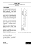
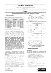
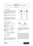
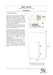
TETRA 43x0 Four Channel Digital Video Multiplexer with Two-Way Audio, Data, and Ethernet USER MANUAL 1. General description TETRA 43x0 (4310 for multimode, and 4350 for singlemode) digital-optical multiplexer/demultiplexer systems can transmit signals through four unidirectional, independent composite video channels and two audio, two contact closure, four data channels, and Fast Ethernet, all bidirectional, independent and transparent, using one single-mode optical fiber per system. Video and data/audio input signals are sampled at a rate of 15 MHz and digitised with 10-bit accuracy. TETRA 43x0 TX transceivers convert and combine composite video, audio, data, contact closure, and Ethernet signals into one digital stream, which in turn is converted into an optical signal, using a wavelength of 1310 nm. The TETRA 43x0 TX also converts and decodes an incoming 1550 nm optical signal carrying a digital stream of data, audio and contact closure signals. A TETRA 43x0 RX transceiver receives, converts and decodes the video and other signals arriving through the optical fiber. It also converts and combines audio/data/contact closure, and Ethernet inputs, then transmits this information optically towards the complementary TX, using an optical wavelength of 1550 nm. The composite video channels can all individually be set to transparent mode (i.e. video clamping off), and the video channel operation mode and several switching functions are accessible through software, using the SmartNet management system (SNM). Several aspects of data and audio interfacing can be controlled by means of circuit board dip switches and jumpers. The data port D1 and D3 interfaces can be set for compatibility with RS-422, RS-485 2W, RS-485 4W, and Manchester PTZ (bi-phase) data. In addition, using modified cabling, the RS-422 interface can be set up for digital current loop/TTY applications. Data ports D2 and D4 are set up for adjustment-free RS-232 operation. The inputs of the 4-wire audio interfaces can be set to high or low impedance, balanced or unbalanced. Contact closures are normally open. Figure 1. Tetra 43x0 RX front panel. TX panels look similar, with video inputs instead of outputs. See table 1. Stand-alone models (/SA option, see supplementary /SA-2 manual) need separate 12 Vdc power supplies. A Siqura PSA 12 DC-25 would be suitable. Front panel status LEDs indicate DC power good, video signal presence, local and remote link synchronization and data activity (see section 2). TETRA 43x0 units are double-width (14TE) Eurocardsized modules and should be used in combination with MC 11 or similar power supply cabinets, the EB-2 versions of these cabinets offering SNM management. © Siqura 2015 Version 071708-1f TETRA43x0TX&RX (MW10) 1 2. Indications and connectors Table 1 lists the front panel features of TETRA 43x0 modules (refer to figure 1). Connector pin assignments are detailed in section 6. TETRA 43x0 TX o (SC/UPC connector) o (BNC connector) 1-8 TETRA 43x0 RX o (SC/UPC connector) o (BNC connector) 1-8 Optical video/data out, optical data in Composite video in Optical video/data in, optical data out Composite video out TETRA 43x0 TX and RX Figure 2. Location of configuration jumpers on the Data/Audio/Ethernet Circuit Card. To access, see “Configuration”, and figure 3. (4x) Front panel screws AUDIO&DATA (modular front panel sockets): audio 1, contact closure 1 A1/CC1 audio 2, contact closure 2 A2/CC2 RS-485 (422)/ RS-232 D1/D2 RS-485 (422)/ RS-232 D3/D4 Status indicator LEDs SYNC DC (green) NV (red) No sync from optical in, or no internal sync (orange) No sync @ remote opt. in (green) All sync OK DC power OK (red) TX: no video in RX: no video out Note: They will always be OFF when the transmit input clamp is disabled. *D1 S422/485/Manchester (red/green) D2 RS232 ( red/green) *D3 R4224/85/Manchester (red/green) D4 RS232 ( red/green) 10 (on Ethernet Port, Amber) 100 ( on Ethernet Port, Green) If the data input is a steady logical “1”, or if there is data activity, the LED will be ON. The LED colour will follow the data, Red = 0/false, and Green = 1/True ON with LINK at 10 Mbps, Blinks with Activity ON with LINK at 100 Mbps, Blinks with Activity Table 1. TETRA 43x0 front panel features * If the D1 or D3 LED indicates steady Green when the input is connected but no signal is being transmitted, either the leads are reversed or, if not, the input bias (BR) should be enabled. Figure 3. Access to internal configuration switches and jumpers 3. Configuration Data interface selection: The four position D1/D3 SEL dip switch (S4) settings determine whether the D1 and D3 data ports operate in RS-422, RS-485 4W, RS-485 2W, or Manchester (Bi-phase) mode, per table 2. In addition, properly setting the Four position LINE BIAS, CONFIGURATION, AND TERMINATION dip switches is essential for proper operation. See figure 2, table 3, and the R-S422, R-S485, and Manchester Line Bias, Configuration, and Termination section. To access the internal set-up switches for the audio, data, and Ethernet circuits, remove the four screws on the front panel as indicated in figure 3, below, and slide out the circuit card assemblies. Contact Closures There is no set-up required for Contact Closure operation. Refer to fig. 4 for hook-up. At the input, connect the input contacts between CC IN and GND. When this connection is made at the input, the CC OUT A and CC OUT B outputs at the far end are connected together. If SYNC is lost, the contacts open. 2 Interface type RS-422 RS-485 4W RS-485 2W Manchester port D1 1 2 ON OFF OFF ON OFF OFF ON ON position, the RS-485 input is unterminated. When both are set in the ON position, the differential input is terminated with 120 ohms resistance. For RS-485 installations, there might be anywhere from 2 to 32 RS-485 devices attached to the differential bus. Normally, the devices at the two extremes of the bus are terminated, whereas intermediate devices are not. port D3 3 4 ON OFF OFF ON OFF OFF ON ON Table 2. Selecting D1 and D3 interface types using the D1/D3 SEL dip-switch, S4 Note: The Factory Default Setting is RS-485 4W Input Configuration: Switch positions 3 and 4 select AC (OFF) or DC (ON) input coupling. RS-422 and RS-485 inputs are always DC coupled and Manchester inputs are always AC coupled. Current loop output: (Select RS-422 for current loop operation). The output impedance of ports D1 and/or D3 can be made suitable for digital 20 mA current loop/TTY applications by pulling a 2-pin jumper (pins 2-3) from the board, thus inserting a resistor in the non-inverting data output line (in order not to lose it, the jumper may safely be parked on pins 1-2). See fig. 2 for the location of the D1 and D3 Current Loop Output jumpers. Current loop I/O should use only non-inverting lines and signal ground (as in figure 3); input signalling on A/GND needs >4V. RS-485 2W and 4W Line Receiver Input Bias (BR): Switch positions 5 and 6, when ON, connect 390 ohm bias resistors on the A and B inputs. The A input is biased towards (+V) and the B input is biased towards (-V). This bias ensures that the input line receiver interprets the state of the differential bus as a logical “zero” while all the drivers attached to the differential bus are in a Hi-Z state. There must be at least one device on the differential bus with the Line Receiver Input Bias (BR) enabled. Typically, BR is enabled along with the termination at one end (only) of the bus. However, if other devices occupy the end positions on the bus, and are terminated, it needs to be ensured that there is adequate bias on the bus for proper operation. Sometimes other devices provide bias. If not, enable BR on one of the TETRA 43x0 units on the bus. To determine if adequate bias is present, while there is no data activity on the bus (disable the master unit if required) attach the (+) lead of a VOM to the “A” lead of the bus and connect the (-) lead to the “B” lead of the bus and take a voltage measurement. For optimum operation, the reading should be at least +200 mV. If it is less, and there are operation problems, enable BR by setting switches 5 and 6 in the ON position on at least one TETRA 43x0 connected to the bus. jumper removed A (IN+) A (OUT+) B (IN-) B (OUT-) GND 220 ohm, internal GND Figure 3. Current loop connections (port D1 and D3). The “B” leads should not be connected. RS-422, RS-485, and Manchester Line Bias, Configuration, and Termination: In addition to selecting the data interface type, the two Four position dip-switches (see fig. 2) marked “DATA SELECT 1” and “DATA SELECT 3”, must be set as prescribed for proper operation. Refer to table 3. Four Position Data Select Dip-Switches for D1 and D3 1 2 3 4 5 6 7 RS-485 4W RS-485 2W RS-422 Mancheste r T T ON ON BR BR T T ON ON BR BR O N O N O N O N ON ON BR BR OF F OF F OF F OF F RS-485 4W Line Driver Output Bias (BD): Switch positions 7 and 8, when ON, connect 390 ohm bias resistors on the A and B outputs. The A output is biased towards (+V) and the B output is biased towards (-V). This bias ensures that the input line receivers in other RS-485 4W devices connected to the bus interpret voltage level on the bus as a logical “zero” while the TETRA 43x0 RS-485 4W output is in the Hi-Z state. Sometimes other devices provide this bias. If not, enable BD on one of the TETRA 43x0 units on the bus by setting switches 7 and 8 in the ON position. To determine if adequate bias is present, while there is no data activity on the bus (disable the master unit if required), attach the (+) lead of a VOM to the “A” lead of the bus and connect the (-) lead to the “B” lead of the bus and take a voltage measurement. For optimum operation, the reading should be at least +200 mV. If it is less, and there are operation problems, enable BD on at least one TETRA 43x0 connected to the bus. 8 BD BD OF F OF F OF F OF F OF F OF F Table 3. Data I/O Configuration, Termination, and Biasing for ports D1 and D3. See text for the definition of “T”, “BR”, and “BD”. Note: The Factory Default Setting is All switches ON (RS485 4W, Terminated and Biased) RS485 Termination (T): Switch positions 1 and 2 operate in tandem. When both switches are in the OFF 3 Ethernet Mode Select: The default settings for Ethernet operation (all switches OFF) enables automatic speed and half duplex/full duplex negotiation. However, the Ethernet Mode Select dip-switch can be used to force the Ethernet port into one particular mode by setting the appropriate switch ON (set ONLY one on), either 100 Mbps full duplex (1), 100 Mbps half duplex (2), 10 Mbps full duplex (3) or, 10 Mbps half duplex (4). power supplies) and connect suitable video and optical fiber equipment using appropriate cabling. CLEAN THE OPTICAL FIBER CONNECTORS PRIOR TO INSERTION INTO THE OPTICAL PORT. For long electrical links, twisted pair wiring should be used. Through-connecting the signal ground lines is recommended; equipment and cabling should be installed and earthed such that protection is provided against lightning and similar influences. 2. Upon powering up, at least the green DC LEDs and SYNC LEDs should glow green, indicating link integrity. If an RX SYNC LED shines red, there is no link synchronization. A TX SYNC LED glowing red indicates that the unit is faulty. 3. With the optical link in good order, connecting a video signal should make the corresponding channel's TX and RX NV LEDs go out. An RX NV LED still lit would indicate that no decodable video signal is arriving through the associated channel. If SYNC problems occur after powering up, please check the optical link first. If the D1 or D3 LED is On, solid Green while there is no data activity, the signal leads might be reversed or BR bias needs to be applied to insure that the line receiver on the input interprets a Hi-Z state as a logical Zero. See “RS-485 2W and 4W Line Receiver Input Bias (BR)” Audio Switch Settings: Refer to table 4 and figure 2. Input impedance Select: The audio input impedance for each channel can be chosen to be 600 Ώ or Hi-Z (high impedance) via S5, switch positions 1 and 2. Input Balanced or Unbalanced Select: Each audio input can accept either balanced or unbalanced audio signals. Balanced or Unbalanced may be selected via S5, positions 3 and 4. The connections for each are the same. In Balanced mode the coaxial cable shield, which connects to Audio IN (-), is grounded. AUDIO SWITCH SETTINGS Audio Channel One S5 1 INPUT OUTPUT Audio Channel Two S7 3 1 S5 2 S7 4 Balanced OFF OFF Unbalanced ON ON Hi-Z OFF OFF 600Ώ ON ON 2 1 Balanced ON ON Unbalanced OFF OFF 8 Table 4. Audio Input Impedance and Balanced/Unbalanced Select Note: The Default Setting is Unbalanced, Hi-Z 1 Audio Balanced or Unbalanced Output Level Select: On the output side, the connection of the cabling determines if the output is balanced or unbalanced. For balanced operation, connect to Audio OUT (+) and Audio OUT (-). For unbalanced operation, connect the signal lead to the Audio OUT (+) and the coaxial cable shield to GND (Ground). Do not connect to Audio (-) for unbalanced operation. The Audio Balanced or Unbalanced Output Level Select switches, S7 maintain a voltage gain of unity for each connection configuration. 8 AUDIO1 IN + AUDIO1 IN GND CC1 OUT B CC1 IN (ref. GND) CC1 OUT A AUDIO1 OUT AUDIO1 OUT + RS-485/422-1 IN + ** RS-485/422-1 IN - ** RS-232-1 IN RS-232-1 OUT GND GND RS-485/422-1 OUT RS-485/422-1 OUT + Figure 4. Socket pin assignments. The second port (A2/CC2) is similar in layout to port A1/CC1/ while the bottom port (D3/D4) is similar to the third (D1/D2). Input connector pins marked ** is the Input and Output for RS-485 2W operation (see text). 4. Installation 1. Plug the modules into the appropriate power supply cabinet (or hook up the /SA-2 models to corresponding 4 5. Care and maintenance Video No. of channels Video format Input/Output level DC restore(clamping) Bandwidth (-3 dB) Sampling res @ freq. Video sampling rate Differential gain Differential phase Group delay SNR For reliable operation of TETRA 43x0 modules, observe the following precautions: - Prevent dust from collecting on the equipment - Protect the equipment against moisture - Maintain sufficient free space around the equipment for cooling. 6. Port connector pin assignments 4 PAL/NTSC 1, nominal Vpp On or off (software selectable) 6 MHz 10-bit @15.0 MHz 27 MSamples, 2x oversampled <2 % <1 ° <40 ns >63 (wtd.) dB Audio The modular port pin assignments (see table 5) are such that similar ports of different units may be connected back to back with reversed cable (RS-232 interfaces excepted). See figure 4 for the socket pin numbering convention used. For 2-wire RS-485 links, I/O is through pin 1 and 2; the units can be connected to older Siqura VAD/ADS models using the older-style cable layout. The more recent models always use pin 1 and 2 for 2wire I/O. Pin 1 2 3 4 5 6 7 8 Port 1 (2) Audio in + Audio in GND CC out B CC IN (ref. to GND) CC out A Audio out Audio out + Pin 1 2 3 4 5 6 7 8 Number of channels Bandwidth, -3dB, typ Sampling resolution In-/output level SNR Total harmonic distortion Input impedance Output impedance Number of channels Data format Interface support Port 3 (4) RS-485/422 in + (**) RS-485/422 in - (**) RS-232 in RS-232 out GND GND RS-485/422 out RS-485/422 out + Number of channels Input Input activation Output Switch rating TX Output Wavelength 1310 1310 RX Output Wavelength 1550 1550 No. of fibers, fiber type 1, MM 1, SM TX Output Power >-4 >-4 RX Min.Input Power -22 -23 TX to RX Link Budget 18 19 Rx Output Power >-8 >-8 TX Min. input power -20 -23 RX to TX Link Budget 20 24 Link Length, Max 21 202 1 Range may be limited by fiber bandwidth. 2 Range limited by return path @ 1550 nm. 3 RX ED 1550 nm dfb laser 1310 1550 1, SM >-4 -23 19 >-8 -23 24 403 4 (full duplex) Asynchronous, serial Current loop, TTY, TTL, Manchester, Bi-phase 2 (full duplex) +5 V pull-up, 10 k 0.75 V (<1.5 k to ground) NO, fail-safe, potential-free 1 A @ 30 Vdc Environmental and Safety Operating temp. -40 to +74 C Relative humidity < 95 % (no condensation) MTBF >100,000 hrs Electrical safety AL / IEC / EN 60950-1 UL recognition file E242498 Laser safety IEC 60825-1, IEC 60825-2 EMC immunity EN 55024, EN 50130-4, EN 61000-6-2 EMC emission EN 55022 (Class B) FCC 47 CFR 15 (Class B) *In the following Optical Specifications section: a) 4310 refers to a TETRA 4310 TX and TETRA 4310 RX pair for multimode operation b) 4350 refers to a TETRA 4350 TX and TETRA 4350 RX pair for single-mode operation c) 4350/ED refers to a TETRA 4350 TX and TETRA 4350 RX pair for extended distance single-mode operation 4350/ED* 47 k or 600 balanced 47 balanced Contact Closure The technical specifications of the TETRA 43x0 system are listed in table 6 below. 4350* dBV dBA Data interfaces D1, D3 RS-422, RS-485, or Manchester, selectable D2, D4 RS-232 Data Rate, D1 DC to 256*** kbit/s (3 MSamples/s) Data Rate, D3 DC to 128*** kbit/s (1.5 MSamples/s) Data Rate, D2 and D4 DC to 115.2 Kbits/s (1.5 MSamples/s) 7. Technical specifications 4310* Hz Data Table 5. Pin assignments of the modular electrical ports (**) Input AND Output for RS-485 2 Wire operation Optical 2 (full duplex) 20 to 20K 16-bit 0 nom, ( +6 max) > 75 < 0.25% at nominal level Electrical Supply voltages 11-15 (/SA) Vdc Power consumption <12**** W Unit Current 0.6, maximum A TETRA 43x0 Mechanical nm Optical connector SC/UPC nm Video connector BNC 75 Data, Audio, Contact socket (4x) for RJ-45 plug dBm Cl. connectors dBm Dimensions HxWxD =128 x 71 x 190 mm dB Weight (approx.) 900 g dBm dBm **) D1 and D3 can be wired for digital 20 mA current loop/TTY dB ***) Manchester / biphase 32 kbit/s typical km ****) 2 A inrush Table 6. TETRA 43x0 TX/RX technical specifications 5 8. Safety, EMC, ESD Optical safety General This optical equipment contains Class 1M lasers or LEDs and has been designed and tested to meet IEC 60825-1:1993+A1+A2 and IEC 60825-2:2004 safety class 1M requirements. Optical equipment presents potential hazards to testing and servicing personnel owing to high levels of optical radiation. When using magnifying optical instruments, avoid looking directly into the output of an operating transmitter or into the end of a fiber connected to an operating transmitter, or there will be a risk of permanent eye damage. Precautions should be taken to prevent exposure to optical radiation when the unit is removed from its enclosure or when the fiber is disconnected from the unit. The optical radiation is invisible to the eye. Use of controls or adjustments or procedures other than those specified herein may result in hazardous radiation exposure. The installer is responsible for ensuring that the label depicted below (background: yellow; border and text: black) is present in the restricted locations where this equipment is installed. The locations of all optical connections are listed in the Indications and Connectors section of this manual. Optical outputs and wavelengths are listed in the Technical Specifications section of this manual. The safety information contained in this section, and on other pages of this manual, must be observed whenever this unit is operated, serviced, or repaired. Failure to comply with any precaution, warning, or instruction noted in the manual is in violation of the standards of design, manufacture, and intended use of the unit. Installation, adjustment, maintenance and repair of this equipment are to be performed by trained personnel aware of the hazards involved. For correct and safe use of the equipment and in order to keep the equipment in a safe condition, it is essential that both operating and servicing personnel follow standard safety procedures in addition to the safety precautions and warnings specified in this manual, and that this unit be installed in locations accessible to trained service personnel only. Siqura assumes no liability for the customer’s failure to comply with any of these safety requirements. UL/IEC/EN 60950-1: General safety requirements The equipment described in this manual has been designed and tested according to the UL/IEC/EN 60950-1 safety requirements. If there is any doubt regarding the safety of the equipment, do not put it into operation. This might be the case when the equipment shows physical damage or is stressed beyond tolerable limits (e.g. during storage and transportation). Before opening the equipment, disconnect it from all power sources. The equipment must be powered by a SELV*) power supply. When this unit is operated in extremely elevated temperature conditions, it is possible for internal and external metal surfaces to become extremely hot. Hazard Level 1M 6 EMC ESD The equipment has been tested and found to meet the CEregulations relating to EMC, and complies with the limits for a Class B device, pursuant to Part 15 of the FCC rules. These limits are designed to provide reasonable protection against interference to radio communications in any installation. The equipment generates, uses and can radiate radio frequency energy; improper use or special circumstances may cause interference to other equipment or a performance decrease due to interference radiated by other equipment. In such cases, the user will have to take appropriate measures to reduce such interactions between this and other equipment. Any interruption of the shielding inside or outside the equipment could cause the equipment to be more prone to fail EMC requirements. Non-video signal lines must use appropriate shielded CAT5 cabling (S-FTP), or at least an equivalent. If system components, such as cabling (e.g. coaxial cable, data/audio/cc wiring) and/or the units, are used outdoors, ensure that all electrically connected components are carefully earthed and protected against surges (high voltage transients caused by switching or lightning). Electrostatic discharge (ESD) can damage or destroy electronic components. Proper precautions should be taken against ESD when opening the equipment. *) SELV: conforming to IEC 60950-1, <60 Vdc output, output voltage galvanically isolated from mains. All power supplies or power supply cabinets available from Siqura comply with these SELV requirements. 9. Product disposal Recycling The unit contains valuable materials which qualify for recycling. In the interest of protecting the natural environment, properly recycling the unit at the end of its service life is imperative. 7