1
XSNet 1800 SW
(Firmware v.3)
Field-hardened layer-2 Ethernet switch with 2 optical 100Mbit uplinks + 4 10/100Base-T
ports
USER MANUAL
©Optelecom-NKF 2006
Version 1.0a (060604-1a)
XSNet1800SWv3 (MW03SP2)
Table of Contents
Part I: description, features, hardware installation......................................................... 3
1. General description ........................................................................................................................................3
2. Front panel features .......................................................................................................................................3
3. Installation.......................................................................................................................................................4
3.1. Initial configuration notes.........................................................................................................................4
3.2. Hardware installation ...............................................................................................................................4
3.3. Software installation.................................................................................................................................4
Part II: Configuration pages ....................................................................................................... 5
1. Logging in ........................................................................................................................................................5
2. XSNet 1800 Home page ..................................................................................................................................7
3. XSNet 1800 network settings .........................................................................................................................8
4. XSNet 1800 SW alarms ..................................................................................................................................9
5. 1800 SW VLANs ...........................................................................................................................................10
VLAN Control and VLAN Port Control .........................................................................................................11
Settings example ..............................................................................................................................................12
Application example ........................................................................................................................................13
6. XSNet 1800 SW Quality of Service (QoS) ..................................................................................................14
7. XSNet 1800 SNMP management by traps and/or polling ........................................................................15
Introduction .....................................................................................................................................................15
Traps.................................................................................................................................................................15
Polling ..............................................................................................................................................................16
8. XSNet 1800 SW RSTP..................................................................................................................................17
9. XSNet 1800 multicast settings .....................................................................................................................20
10. XSNet 1800 SW Port Settings....................................................................................................................21
11. XSNet 1800 SW port statistics ...................................................................................................................22
12. XSNet 1800 Reboot and restore ................................................................................................................23
13. Technical specifications..............................................................................................................................25
14. Safety, EMC and ESD information...........................................................................................................25
2
PLEASE READ THE DOCUMENT 'QUICK START' BEFORE INSTALLING THIS EQUIPMENT
XSNet 1800 SW v.3
Part I: description, features, hardware installation
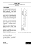
1. General description
XSNet 1800 SW switches have four electrical Ethernet ports, and also
provide up to two independent 100 Mbit optical uplinks through either
dual multimode or dual single-mode fibres (one fibre pair per port), at
wavelengths of 850 nm (MM), 1310 nm, or CWDM (SM), the latter for
longer spans. Also available are medium-span models with one fibre
per optical port. The switch is built as a platform: for its uplink ports, it
uses SFP (Small Form factor Pluggable) packages. The units are
especially suitable for use in outdoor housings.
The non-blocking, highly configurable switches support the following
protocols: ARP, LLC, IP, UDP, IGMP, Spanning Tree (STP) and Rapid
Spanning Tree (RSTP).
Front panel status LEDs provide information about power, port speed
and port activity.
The switches come in the form of single-width (7TE) Eurocassettes
fitting in MC 11 or similar power supply cabinets, or as stand-alone
units (/SA option). Device configuration can be performed in-band
using the built-in http server. In-band device and link management
using a GUI can be performed with the aid of Optelecom-NKF utility
programs based on the MX protocol. In an EB-2 type power supply
cabinet, the switches can be configured and managed with the SNM
protocol [variable by name protocol not implemented].
1
SW
DC
P6
P5
6
5
4
3
2
1
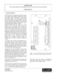
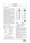
2. Front panel features
The 1800 SW front panel, shown in figure 1, has features as listed in
table 1 below and represented in figure 1.
Feature
Connectors
Optical LC (dual), 5, 6
RJ45, jack, 4x (1-4)
Status LEDs
*DC
green
yellow
(upper)
*1-*4
green
(lower)
off
*P5, *P6
green
Function
optical Ethernet ports
10/100TX Ethernet ports
Figure 1. XSNet 1800 SW front panel
DC power OK
link speed 10 Mbit/s
blinking: data activity
link speed 100 Mbit/s
blinking: data activity
no connection
green: sync OK
blink: data activity
off: no sync received
Table 1. Front panel connectors and indications
{
3
3. Installation
3.1. Initial configuration notes
Before installing and trying to link up the switch in a network, please read the separate guide detailing
how to set the IP address and subnet mask, and if necessary the gateway address, for initial installation.
3.2. Hardware installation
A Eurocassette module will slot into an Optelecom-NKF power supply cabinet, model MC 11 or similar. A
stand-alone model may be mounted in any suitable environment that will not make it overheat or malfunction in
other respects: some natural air circulation, moisture lockout and prevention of dust or grime accumulation are
always desirable.
The switch will power up in a few seconds, performing auto-negotiation on the 10/100 Mbit ports. The
Spanning-Tree Protocol (if applicable) and Rapid Spanning-Tree protocol have convergence times of 10-30 and
typically 4 seconds, respectively. Generally, the ports will all be up and running within a minute after powering
up into a network.
3.3. Software installation
Only the items needed for putting the switch into operation, and some auxiliary features, will be described here.
With in-band configuration using the built-in HTML pages, the main switch parameters can be set. The
following chapters contain a description of how to go about this.
4
XSNet 1800 SW
Part II: Configuration pages
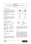
1. Logging in
Logging in to the XSNet 1800 SW internal http server enables the user to configure the switch without using
separate application software. A standard Web browser will suffice to find the module by its IP address.
Activate the LOGIN button on the login screen that will appear (see figure 1 below).
Figure 1. Part of the first screen: Login pane
After the Connect box appears (see below), a fresh module can be accessed as follows:
-
login as ‘admin’
leave the password field blank
activate the OK button or press ‘Enter’
Figure 2. Login box
5
After completing login, the Home page (see the Homepage section) will appear.
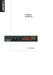
Figures 3a,b. Page selection menu (left) and port connections
The other HTML pages can be called up next from the navigation menu appearing in the top left corner of each
page (figure 3a); each page may consist of several sections. Each section has an information button
, which
can be activated to display help.
The HTML pages share the following features:
-
a menu to access the pages (see figure 3a)
a diagram (figure 3b) showing which ports are in use, i.e. connected to another active device
panes (sections) showing parameter values, some of which are editable
buttons, mainly SAVE, REFRESH and CANCEL, for sections with editable fields
Writing changes into the device after editing is done by activating the SAVE button.
The actual values still in the device are shown using the REFRESH button.
Activating CANCEL undoes any changes made before saving and shows the values as they were before editing.
Main operational variables and modes to be set are (see also figure 3a):
-
Network addresses
Port speed and mode
Unicast and multicast
RSTP (spanning tree/rapid spanning tree protocol) settings
6
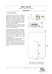
2. XSNet 1800 Home page
This page (see figure 4) has the following sections:
-
Identification pane: administrative data, including the article code, serial number, software version, and
uptime
Labels pane: label entries (editable)
Status pane: an alarm status overview (alarms active or not), including the level of the highest occurring
configured alarm (Module status field).
Figure 4. Home page, with Identification, Labels and Status sections
On this page, only the 32-character labels can be edited; please activate the SAVE button if after making changes
you wish to make them definitive and active. However, if you decide to stop editing and return to view the
original values, use either the REFRESH or the CANCEL button.
The Module status will be ‘OK’ if there is no configured alarm active (see the Alarms page); otherwise it could
appear as a character from A-N, depending on the alarms configuration.
7
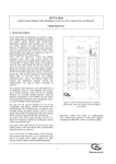
3. XSNet 1800 network settings
Figure 5. Network page
For correct functioning of the 1800 SW, it is essential to set its network addressing to be compatible with the
subnet it is hooked into; see figure 5.
The Network settings pane shows the IP address. It is essential to set at least this address correctly and to
keep the value on record, otherwise management of the switch will require special software. Note that the
subnet address is also required.
After setting a new IP address, press the REBOOT button to activate the new setting. In-band communication
with the 1800 SW will be interrupted and the user will have to contact the device again using the new IP address.
The Subnet and Gateway settings show the subnet mask and default gateway. Assuming the device IP address
and subnet mask are already set correctly, only the default gateway needs to be defined in order to connect the
network segment to others.
The entries in the MX alarm settings pane serve to support a video IP system using the MX protocol. The setting
shown (255.255.255.255) indicates the MX packets are being broadcast.
After filling in the addresses, use the SAVE button to set them.
8
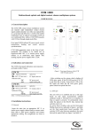
4. XSNet 1800 SW alarms
The Alarms settings page shows the Status and Alarm level settings panes. In the Status pane, the Module Status
entry shows the highest level of the occurring and configured alarms, while the other fields in that pane represent
the actual status of some alarms. These alarms are not necessarily assigned a level; this can be done in the pane
‘Alarm level settings’.
Figure 6. Switch alarms configuration page
Alarm levels can be set to A-N, or to ‘_’ (equivalent to ‘O’), the latter meaning no alarm level set. In the
example screenshot, one alarm level was already set and another was in the process of being set. Setting an alarm
level A-N also means the alarm will actually go off if a certain condition is met. For the 1800 SW, these
conditions are:
Power supply alarm
Temperature alarm
Link loss alarm (port 5)
Link loss alarm (port 6)
Bad connection alarm
(ports 5 & 6)
Indicates an active power supply alarm (2V5 or 3V3
outside 5% of their nominal value)
Indicates an active temperature alarm (temperature above
the selected value, default is 70oC)
Indicates link of 100 Mbit port 5 is down
Indicates link of 100 Mbit port 6 is down
Indicates whether FX ports 5 and 6 together experienced
more than 10 000 CRC errors (value can be changed
using suitable software)
After setting an alarm level, first activate the SAVE button, then the REFRESH button to update other values
displayed.
9
5. 1800 SW VLANs
XSNet 1800 switches support up to 50 virtual tagged LANs, organizing ports into separate groups. These
VLANs are to be enabled from the VLAN Control menu with at least one entry in the VLAN Port Control menu,
and a management VLAN defined. The latter is essential: without it, all in-band contact with the switch would
be lost. So: define a management VLAN first before enabling VLANs.
The 802.1q tags can contain a VLAN ID and/or a priority level. If only the latter is present, the VID is zero; the
frame is then called a ‘P-frame’ (priority-only frame) not to be confused with a pause frame.
VLAN entries: defining an 1800 SW tagged VLAN
On the VLAN Entries page, use the edit window (see figure 7) to fill in a row for each VLAN you want to
define. For each port, two entries must be considered:
-
the port VLAN membership, indicating that a port should be a member of the VLAN to be defined
(membership of more than one VLAN is of course allowed)
untag (i.e. remove Q-tags), indicating that tags holding VLAN and priority information should be
removed from the output.
For a port connected to another switch, there should be no untagging if the VLAN extends over several
switches. For edge ports, the stream should generally be untagged.
A management computer should be connected to an untagging VLAN port unless the application running on it
and the network interface card involved will handle Q-tags sensibly.
Figure 7. 1800 SW VLAN entries. The arrow indicates the edit window
By clicking on an existing VLAN entry, it can be edited in the edit window, indicated by the arrow. Pressing
SAVE will consolidate the modified entry if the VLAN ID did not change, or add an entry if a new VLAN ID
was added.
Pressing the DELETE button while an entry is present in the edit window will irrevocably disable and remove
that VLAN.
Remember to use the SAVE button to store your VLAN definitions and settings.
Before enabling VLANs on the VLAN control page, be certain to fill in matching VLAN IDs in the VLAN Port
Control pane there.
10
VLAN Control and VLAN Port Control
Before any entry on this page is made, the list on the VLAN Entries page must be filled in.
Figure 8. 1800 SW VLAN control and Port Control settings
If - in the VLAN Control pane - the VLAN Enable box is checked, it is possible to add, remove or modify
Q-tags in packets, according to the ingress rules set in the VLAN Port Control pane (see figures 8 and 11).
If VLANs are enabled, the following ingress options are available:
- incoming Q-tagged frames can be modified as follows (see figure 9):
-
they can be left as they are
the VLAN ID can be changed
both VLAN ID and priority can be changed.
This can be done with the ‘Q-frame’ selection box (see figure 9 below):
Figure 9. 1800 SW VLAN Control , Q-frame menu options
11
- incoming non-Q frames can be handled as follows (see figure 10):
-
a default Q-tag can be inserted
the priority inside the tag is preserved (this if the VLAN ID is zero but a priority value is set)
they can be dropped ( this also for tags in which the VLAN ID is zero)
Figure 10. 1800 SW VLAN Control , non-Q-frame menu options
This can be done with the ‘non-Q frames’ selection box, with the exception of the framesdropping, which is set
by ticking the checkboxes of the ‘Drop non-Q-frames’ row in the VLAN Port Control pane (see figure 11
below).
The ingress rules are defined per port, in the VLAN Port Control pane. There, any port can be configured to drop
non-Q-frames (arrow in figure 11). If set, this has prevalence over tag insertion or modification.
Figure 11. 1800 SW VLAN port ingress rules
Settings example
With VLANs enabled, a port connected to another switch (a non-edge port) would generally be set to:
-
drop non-Q-frames (ingress, per port),
do not untag Q-frames (egress, per port, per VLAN)
An edge device generally does not handle received Q-tags or send such tags. However, at the switch input port, a
Q-tag may be inserted holding a VLAN ID and priority assigned to the device according to the ingress rules
defined in the VLAN Port Control pane, so VLAN Control settings for an edge port would be:
-
untag (egress, per port, per VLAN)
insert default Q-tag (ingress).
The default Q-tag (per port) is defined on the VLAN Control page, under VLAN Port Control.
12
Application example
Internet
Ports 5, 6 are members of
VLAN v1, v5, v10
SW 1
SW 2
IP : 137. 92. 254. 10
Router
tagged frames
IP : 137. 92. 254. 11
vid 1 , 5 , 10
6
6
5
4
5
v5
4
vid 1 , 5 , 10
3
v1
2
v1
1
1
untagged frames
untagged frames
PC
101
v5
tagged frames
3
2
Ports 5, 6 are members of
VLAN v1, v5, v10
PC
203
Figure 12. 1800 SW switches with two VLANs
With the switches SW 1 (137.92.254.10) and SW2 (.11) interconnected (see figure 12), traffic between the
switches should include all packets that have any business on the other switch; this includes the management
packets coming from elsewhere in the network.
Three VLANs (v1, with VLAN ID 1, v5, with VLAN ID 5, and the management VLAN, with ID 10) are
indicated; the other ports belong to other VLANs, either local to the switches or extending over other switches.
At least one port connected to the network must be a member of VLAN 10.
The two PCs (101, 203) connected to the VLAN 1 ports are transmitting and receiving untagged packets. With
VLANs enabled, the ports would be configured as follows:
SW1, port 1; SW2, port 2:
- port ingress: tag with VLAN ID 1 (which would be the most logical choice), priority 0-7
- port egress: untag the VLAN 1 packets going to the device
Both switches, ports 5:
- ingress: Q-frames must be left as they are, non-Q-frames are to be blocked
- egress: here, both ports are member of all three VLANs indicated, so at least the packets tagged with
any of the VIDs (1, 5, 10) indicated are transmitted
SW2, port 6:
If any of the VLANs indicated stretch over more than these two switches, at least the packets belonging to those
VLANs are to be sent out; in the drawing, this port is a member of all VLANs indicated. In any case,
management (VLAN 10) packets must be allowed to travel over the whole network, to allow switch management
from anywhere.
13
6. XSNet 1800 SW Quality of Service (QoS)
Figure 13. The example has QoS enabled, weights of 4 and 1, ports 1-3 set to high priority, and a TCI-threshold of 4.
Enabling QoS on the 1800 SW instates two priority levels (high/low) and corresponding queues, used in case of
network congestion. These levels can be defined as follows:
-
Port based: tagged and untagged frames entering a port marked ‘high’ go to the high-priority queue.
Priority based: per Q-frame (only priority level 0-7 in tag is important). A TCI lo/hi threshold of 1-7
must be set. Tagged frames with a priority level equal to the TCI-threshold and up go into the highpriority queue.
(TCI = tag control information)
Fulfilling either of these two conditions (see the arrows in figure 13) will get a frame into the high-priority
queue.
The H-weight and L-weight entries (values allowed are 0-15), defining how fast the queues are handled, must be
set. They are defined as:
-
H-weight = m (default 4): after handling maximum of m high-priority frames, start with low-priority
frames
L-weight = n (default 1): after a maximum of n low-priority frames, return to handling high-priority
frames.
14
7. XSNet 1800 SNMP management by traps and/or polling
Introduction
To prepare the XSNet 1800 switch for SNMP management, the database documenting the 1800’s variables
amenable to readout and/or modification must be registered with the program; such SNMP MIB documents are
available from our web site.
The System Information pane (on the SNMP HTML page, see figure 14) shows the network/device data
specifically made available to the SNMP manager for making the device, its location and service manager(s)
traceable.
You will always need to set the community strings (names) in the Communities pane to conform to those
configured in the SNMP manager. Often, these are ‘public’, mainly used for the read and trap communities, and
‘private’ or ‘netman’, for read-write operations. The manager software may offer additional choices.
Figure 14. 1800 SW SNMP settings
Traps
Traps generated by the XSNet 1800 SW can be caught by any SNMP manager. Traps can be generated by
configuring an alarm level A-N on the Alarm settings page for the available events or variables to be monitored
using the SNMP manager program.
In the Traps pane (figure 14), at least the following information must be entered:
- the SNMP version used
- the IP address associated with the manager program, and the destination port (162 is a sensible default).
If desired, an alternative destination IP can be added. It is also possible to add an authentication trap to be able to
catch attempts at access using the wrong community string.
15
The 1800 SW will always generate cold boot and port link up traps (if connected) while booting; this behaviour
is fixed through using the SNMP MIB group mgmt:snmp:snmp-Traps:TrapsInfo (in RFC1213-MIB). Linkdown/up traps will be sent when a port is disconnected and connected, respectively.
Polling
Depending on facilities offered by the SNMP manager, a number of variables can be read out and in a few cases
be edited and set. Many 1800 SW variables are contained in the ‘system’ and ‘interfaces’ sections of RFC1213MIB.
The examples and drawing are taken from the Castle Rock SNMPc manager.
Figure 15. Part of the 1800 SW port table called up using Castle Rock’s SNMPc
Figure 16. A number of devices centred around two switches connected to a management PC; diagram drawn by hand in
Castle Rock’s SNMPc.
16
8. XSNet 1800 SW RSTP
Introduction
Rapid Spanning Tree Protocol (RSTP) is an evolution of the Spanning Tree Protocol (802.1D standard) and
provides for faster spanning tree convergence after a topology change.
Figure 17. XSNet 1800 SW (R)STP settings
When RSTP is enabled, it ensures that only one path at a time is active between any two nodes in the network.
We recommend that you enable RSTP on all switches to ensure that only single active paths in the network exist.
The RSTP uses a distributed algorithm to select a bridging device (STP-compliant switch, but it could be a
bridge or router) that serves as the root of the spanning tree network. Then it selects a root port on each switch
(except for the root device) which incurs the lowest path cost when forwarding a packet from that device to the
root device. Thirdly, it designates a switch in each LAN which incurs the lowest path cost when forwarding a
packet from that LAN to the root device. Viewed from the root device, all ports connecting to (the root ports of)
designated switches are assigned as designated ports. After determining the lowest-cost spanning tree, the RSTP
enables all root ports and designated ports, and disables all other non-edge ports. Network packets are therefore
only forwarded between root ports and designated ports, eliminating any possible network loops.
The 1800 SW and RSTP
The XSNet 1800 SW can use the Rapid Spanning Tree Protocol, which can be enabled or disabled for the switch
as a whole, not per VLAN. Port configuration for this protocol works as follows (see the tables in figure 17):
-
under General RSTP settings, specify the values for Bridge priority, Forward delay, Hello time and
Max age. Generally, the defaults shown will suffice.
under RSTP port settings (third pane, Admin Edge column), specify for each port whether it is an edge
port (connected to an end device), or a non-edge port (such as a backbone port)
specify path cost and priority.
SAVE the RSTP configuration, after enabling RSTP on the General RSTP settings pane.
17
Each port 1-6 can be set to be either an edge port or a non-edge port. Edge ports should not be connected to form
loops, since rapid spanning-tree will ignore edge ports. Optical ports 5-6 are factory set to be non-edge ports;
ports 1-4 are set to edge.
RSTP related terminology is explained in table 1.
By default, RSTP is on unless another connected switch within reach of the algorithm is set to use STP.
RSTP Parameter
Priority (bridge)
Max Age
Hello Time
Description
The priority value is used to identify the root bridge. The bridge with the
lowest value has the highest priority and is selected as root. Enter a value
from 1 to 61440.
The Max Age value is the number of seconds a bridge waits without
receiving Rapid Spanning Tree Protocol configuration messages before
attempting a reconfiguration. Enter a time in seconds from 6 to 40.
The Hello time value is the time between the transmissions of Rapid
Spanning Tree Protocol configuration messages. Enter a time in seconds
from 1 to 10.
Forward Delay time The forward delay time is the number of seconds a port waits before
changing from its Rapid Spanning Tree Protocol learning and listening
states to the forwarding status. Enter a time in seconds from 4 to 30.
Port Priority
A port's priority in becoming the root port. The allowed range is between
0-255. Its default setting is 128. The lowest number has the highest priority.
Path Cost
Specifies the path cost of the port. The Switch uses this to determine which
ports are the forwarding ports. The lowest numbers assigned are the
forwarding ports. The range is between 1 and 65535 and the default values
based on IEEE802.1d are:
10Mb/s = 50-600 100Mb/s = 10-60 1000Mb/s = 3-10
EdgePort
Users can enable this option if an interface is attached to a LAN segment
that is at the end of a bridged LAN or to an end node. Specifying EdgePorts
provides quicker convergence for devices such as workstations or servers,
retains the current forwarding database to reduce the amount of frame
flooding required to rebuild address tables during reconfiguration events,
does not cause the spanning tree to initiate reconfiguration when the
interface changes state, and also overcomes other STP-related timeout
problems. However, remember that EdgePort should only be enabled for
ports connected to an end-node device.
Port Role, Port State This will display the ports' roles and states as per their settings. See table 2
below for an RSTP/STP state equivalence table.
Table 1. RSTP glossary
STP (802.1D)
Port State
Disabled
Blocking
Listening
Learning
Forwarding
RSTP (802.1w)
Port State
Discarding
Discarding
Discarding
Learning
Forwarding
Port Included in
Active Topology?
No
No
Yes
Yes
Yes
Table 2. STP and RSTP port states.
18
Port Learning
MAC Addresses?
No
No
No
Yes
Yes
With RSTP not enabled, the switch is still compatible with STP switches, but will not actively partake in the
STP configuration: the ports are all forwarding (see figure 18).
To force full compatibility with STP-only equipment from the start, you will need additional MX configuration
software (set the internal variable Force Version to zero).
Figure 18. XSNet 1800 SW (R)STP with RSTP not enabled
19
9. XSNet 1800 multicast settings
The 1800 SW series switches support multicasting, each group of receivers listening to its own source. Inside a
switch, regular unicast traffic only passes through the central switch matrix, unaffected by the multicast switch
mode. Multicast streams are processed separately, but can share ports with unicast streams.
If multicasting is being used and non-backbone port output is needed, the switch mode needs to be set to 'IGMP
enabled' (see figure 19, first entry under ‘Multicast settings’).
On this page, each port can be set to one of the following modes when the switch handles multicasting:
- Transmitter mode: the switch will block all outgoing multicast traffic for this port. Multicast traffic entering
the port from outside will pass, so this is a switch entry port for a multicast transmitter.
- Receiver mode: outgoing multicast traffic will be allowed to pass, incoming multicast traffic is blocked.
- Backbone port (all multicast): all multicast traffic will internally be forwarded to and appear on the port,
irrespective of IGMP queries or IGMP memberships.
On receipt of a leave message, a port will either (1) if it is an non-edge port, ignore it because still other clients
may have subscribed themselves to that particular multicast stream, or (2) if it is an edge port (such as in an endnode device), be disabled for this stream.
Figure 19. XSNet 1800 SW multicast settings
20
10. XSNet 1800 SW Port Settings
While in a network, enabled ports in the 1800 SW will have to use a link mode compatible with ports of
connected devices. This can be done by selecting auto-negotiation (see the ‘link mode’ column in the table
below) or by setting duplex/half duplex and link speed per port manually. The negotiation results appear in the
speed, duplex and pause (the switch is able to send and receive pause frames) columns. If auto-negotiation is
used, enabling, sending and receiving of pause frames is automatic.
Note however that the high-speed ports 5 and 6 only offer auto-negotiation or, if this is set to off, the fixed
setting 100 Mbit full duplex.
Figure 20. XSNet 1800 SW port/link settings
21
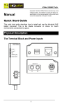
11. XSNet 1800 SW port statistics
Figure 21. XSNet 1800 SW port statistics
The 1800 SW port loads are represented in figure 21. Transmit and receive port loads are shown in terms of
maximum loads (per port) in the upper two graphs, while received packet size and error statistics are depicted in
the lower two.
22
12. XSNet 1800 Reboot and restore
From this page (figure 22), the 1800 SW can be rebooted, either keeping its settings, only keeping its network
settings, or restoring all factory defaults, including its network settings:
Figure 22. XSNet 1800 SW Rebooting and restoring settings
-
in the field marked ‘Reboot’ (figure 23), the ‘Stay operational’ option does exactly what it says: the unit
will continue to operate even if the REBOOT button is activated (the similar button on the Network
page however always makes the switch reboot).
Figure 23. XSNet 1800 SW Reboot options
-
with the option ‘Reboot’, the switch will retain all its settings when rebooting with the option ‘Keep
settings’ under ‘Restore default settings’ (figure 24). This can for instance be used after changing
network settings. However, in the latter case, rebooting is best done from the Network page. The other
option ‘Restore factory defaults’, should be used judiciously.
Figure 24. XSNet 1800 SW Reboot options
-
‘Erase network settings and reboot’ resets the network settings to their default values
23
Overview of reboot/restore:
‘Reboot option’
stay operational
reboot
‘Restore default settings’ option
any setting
keep settings
reboot
restore factory defaults
erase network settings and reboot
erase network settings and reboot
keep settings
restore factory defaults
24
Effect on reboot
will do nothing
reboot the switch without changing
values
resets all user values except
network settings
network settings reset
full reset
13. Technical specifications
14. Safety, EMC and ESD Information
General
XSNet 1800 SW
1800
/SM-10,
BiDi
1800
/SM-60,
/CWDM-λ
The safety information contained in this section, and on
other pages of this manual, must be observed whenever this
unit is operated, serviced, or repaired. Failure to comply with
any precaution, warning, or instruction noted in the manual
is in violation of the standards of design, manufacture, and
intended use of the unit.
Installation, adjustment, maintenance and repair of this
equipment are to be performed by trained personnel aware of
the hazards involved. For correct and safe use of the
equipment and in order to keep the equipment in a safe
condition, it is essential that both operating and servicing
personnel follow standard safety procedures in addition to the
safety precautions and warnings specified in this manual, and
that this unit be installed in locations accessible to trained
service personnel only.
Optelecom-NKF assumes no liability for the customer’s
failure to comply with any of these safety requirements.
1800
/MM
Optical
Optical ports
Output wavelength
Laser type
Receiver PIN
Ribre type
Housing
Optical span
Min. fibre length
2 x 100 BASE-FX
1310 nm, or
1550, or
850 nm
1310/1490
CWDM
On request (SFP package dependent)
On request (SFP package dependent)
2x2x SM
2x2x SM
2x2x MM
or 2x1x
SM (BiDi)
SFP (MSA compliant)
10 km
60 km
> 2 km
2m
2m or
2m
>10 km
(CWDM)
Performance
Address table size
Switching method
Switching fabric
UL/IEC/EN 60950-1: General safety requirements
4k entries
store and forward
non- blocking
The equipment described in this manual has been
designed and tested according to the UL/IEC/EN 60950-1
safety requirements.
If there is any doubt regarding the safety of the equipment, do
not put it into operation. This might be the case when the
equipment shows physical damage or is stressed beyond
tolerable limits (e.g. during storage and transportation).
Before opening the equipment, disconnect it from all power
sources. The equipment must be powered by a SELV*) power
supply.
When this unit is operated in extremely elevated temperature
conditions, it is possible for internal and external metal
surfaces to become extremely hot.
Ethernet I/Os
Number of ports
10/100Base-TX
802.3u
100Base-FX
Full-duplex 802.3x
6
4
2
yes
Standards
IEEE 802.3
IEEE 802.3a,b
IEEE 802.3u
IEEE 802.3x
IEEE 802.1d
IEEE 802.1d/t/w/z
RFC 2236
10BASE-T
100BASE-FX
100BASE-TX
Full-duplex operation
Spanning Tree Protocol
Rapid Spanning Tree Protocol
IGMP v2
EMC
The equipment has been tested and found to meet the CEregulations relating to EMC, and complies with the limits
for a Class B device, pursuant to Part 15 of the FCC rules.
These limits are designed to provide reasonable protection
against interference to radio communications in any
installation. The equipment generates, uses and can radiate
radio frequency energy; improper use or special
circumstances may cause interference to other equipment or a
performance decrease due to interference radiated by other
equipment. In such cases, the user will have to take
appropriate measures to reduce such interactions between this
and other equipment.
Any interruption of the shielding inside or outside the
equipment could cause the equipment to be more prone to fail
EMC requirements.
Non-video signal lines must use appropriate shielded CAT5
cabling (S-FTP), or at least an equivalent.
If system components, such as cabling (e.g. coaxial cable,
data/audio/cc wiring) and/or the units, are used outdoors,
ensure that all electrically connected components are
carefully earthed and protected against surges (high voltage
transients caused by switching or lightning).
Powering
Power consumption
Supply current
Rack-mount units
Stand-alone units
(/SA)
<6W
0.6 A
MC 1x power supply cabinets
11 to 19 Vdc
(PSA 12 DC/25) or PSR 12 DC
Management
LED status indicators
DC LED
Sync port 5, 6
LED port 1 t/m 4
network management
power- on indicator OK = GREEN
link = GREEN; link activity =
GREEN blinking ; no link = off
10 Mb = YELLOW ; 100 Mb =
GREEN; blink is activity
SNM™ compatible / out-of-band
MX/IP™ inband
Environmental and safety
Operating temperature
Relative humidity
MTBF
General safety
UL recognition file
Laser safety
EMC emission
EMC immunity
-40 to + 74°C
< 95 % (no condensation)
> 100,000 h
IEC/EN 60950-1
E242498
IEC 60825-1, IEC 60825-2
EN 55022 (class B),
FCC 47 CFR 15 (class B)
EN 55024, EN 50130-4, EN 61000-6-2
ESD
Electrostatic discharge (ESD) can damage or destroy
electronic components. Proper precautions should be
taken against ESD when opening the equipment.
Mechanical
Optical connectors
Network connectors
Dimensions
Weight (approx.)
Housing
duplex LC
RJ45 (8x)
128 mm x 34 mm x 190 mm (7TE)
900 gram
rack-mount or stand-alone
*)
SELV: conforming to IEC 60950-1, <60VDC output, output
voltage galvanically isolated from mains. All power supplies or
power supply cabinets available from Optelecom-NKF comply
with these SELV requirements
25