1
ADS 1200
Audio, data and contact closure multiplexers for fibre-optic links
USER MANUAL
1. General description
ADS 1200 systems offer combined full duplex
transmission of data, audio and contact closure
signals, all independent, over one or two multimode or
single-mode optical fibres (TRA/TRB or TRX
respectively, see figures 1a,b). For technical
specifications please consult section 5.
Two 4-wire audio channels and two contact closure
channels are available on the topmost pair of modular
connectors (port 1 and port 2). The data section
comprises two RS-485/RS-422 (Manchester and
biphase compatible) and two RS-232 channels, on the
two lower modular connectors.
Internal dip switches control the configuration (2/4
wiring and type; default is 4-wire RS-485) of the RS4xx interfaces. If necessary, the RS-485 interfaces can
be adapted to use biasing; by default, the data
interfaces are transparent. By removing a jumper and
output rewiring, port D1 can be used for digital
current loop. Audio input impedance is jumper
selectable. The contact closure outputs are potentialfree and open on synchronization failure.
LEDs indicate power and local as well as remote sync
status (see section 2), and also monitor data I/O.
The 7TE modules will slot into the backplanes of
NKF's MC 10 or MC 11 power supply cabinets.
Stand-alone models (/SA option, see supplementary
manual) needs an external 12 VDC power supply.
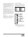
2. Connectors and indicators
Indication
o← (ST or FC connector)
o→ (ST or FC connector)
o↔ (ST or FC connector)
Meaning
Optical input (two-fibre units)
Optical output (two-fibre units)
Optical input/output
(single-fibre units)
Modular sockets:
A1/CC1
A2/CC2
D1/D2 (D1: see text)
D3/D4
audio1, contact closure 1
audio2, contact closure 2
RS-485 (422), RS-232
RS-485 (422), RS-232
System status LEDs:
*SYNC
(red) No sync from optical in,
or no internal sync
(orange) No sync @ remote optical in
(green) All sync OK
(green) DC power good
*DC
Data status LEDs:
*D1, *D3
*D2, *D4
red/green RS-485 input to D1,3 = 1/0
off high-Z
green/off RS-232 input to D2,4 =1/0
Table 1. Connectors and indications on the ADS 1200 front
panel (the modular sockets will take RJ45 plugs)
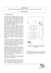
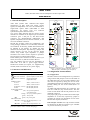
Figure 1. ADS front panels: TRA (left, similar to
TRB, one-fibre), and TRX (right, two-fibres)
3. Configuration and installation
3a) Configuration
Interface selection and configuration are performed
using switches and jumpers on the circuit boards of
the ADS 1200 units. To access these elements, each
unit must be opened by taking out the two front
panel Phillips head screws indicated in figure 1 and
partially sliding out the circuit board (shown in
figure 2).
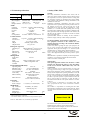
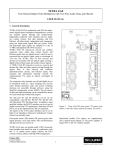
An ADS 1200 data board has two 8-fold (S1, S2)
and one 4-fold (S3) dip switch blocks. The first
switch of each block and the ON positions are also
indicated in figure 2.
The jumper-pin groups A and B control audio input
impedance of A1 and A2, respectively; jumper C
regulates the current loop impedance of one of the
RS-485 data outputs (see below).
Data interface selection: the 4 dip switches in bank
S3 determine the RS-4xx interface type available
on ports D1 and D3 as per table 2.
impedance resistors to both input and inverting
input (see table 3 below).
1
2
3
A
1
2
3
B
1
2
3
Switch
Function (RS-485 mode set)
bank S1 for D1
bank S2 for D3
1-3
dwell time select, see table 4
4 ON
inverting input tied to +5V over 390 Ω
5 ON
inverting input tied to +5V over 10 kΩ
6 ON
line termination 120 Ω (default = off)
7 ON
input tied to GND over 10 kΩ
8 ON
input tied to GND over 390 Ω
Table 3. Choosing bias resistances, dwell times and line
termination for interfaces D1 and D3
ADS TRX 650 2033 3
WWJJ
C
U603
S2
S1
1
S3
1
1
ON
Figure 2. ADS TRA/B printed circuit board; details left out
for clarity. Please take care not to damage the optical
fibre floating above the board.
Please note that the 'soft zero' biasing adaptation
method used ties the inverting ('negative') input to
the higher voltage, while the biasing resistor of the
normal input is tied to signal ground. This will
provide a well-defined bus state when no driver is
active.
The first three dip switches of the banks S1 and S2
on the circuit boards (see figure 3) are used to
configure the tristate-sensing/dwell timing of
interface D1 and D3, respectively, if biasing of RS485 lines is used, to help indicate the conclusion of
transmission (table 3). Dwell time is approximately
10*bit length or slightly longer.
Interface
port D1
port D3
S3-1 S3-2 S3-3 S3-4
type ↓
RS-485 2-w.
0
0
0
0
RS-485 4-w.
0
1
0
1
RS-422
1
0
1
0
Table 2. Choosing RS-485 interface types
using dip switch bank S3
Two-wire RS-485 mode uses the input terminals for
I/O. In older ADS/VAD units, for two-wire mode the
+ in and + out needed to be combined, as well as - in
and - out; old and new units can be used together with
the old-style cable layout.
Setting
no.
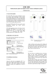
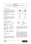
Current loop output: The RS-485 output impedance
of port D1 can be made suitable for digital 20 mA
current loop ('TTY') applications by pulling a 2-pin
jumper (C2-3) from the board, thus inserting a resistor
into the non-inverting data line. The jumper may be
put on pins C1-2 to save it. Current loop I/O should
0
1
2
3
4
5
6
7
jumper removed
A (IN+)
A (OUT+)
B (IN-)
B (OUT-)
GND
Switch
bank S1 for D1
bank S2 for D3
1
2
3
OFF OFF OFF
OFF OFF ON
OFF ON OFF
OFF ON ON
ON OFF OFF
ON OFF ON
ON ON OFF
ON ON ON
Dwell
time
(±7%)
*
**
0.17 ms
0.34 ms
0.67 ms
1.35 ms
2.68 ms
5.38 ms
Data
rate
(bit/s)
0-max
0-max
≥64000
38400
19200
9600
4800
≤2400
*) default, hardware tri-state detect (1V differential sense,
not to be used together with line-biasing)
**) logic high in the data directly drives the output enable
(I.E. no delay). This setting is especially suitable for
very low data rates.
220 ohm,
internal
GND
Table 4. Dip switch settings for unbiased and biased RS485 interfacing. Settings 1-7 all need bias resistors to
define zero.
use only non-inverting lines and signal ground (see
figure 3); the interface type should be set to RS-485
(4-w). Input signal voltage on A-GND (IN+-GND)
should be at least 4V.
Depending on the actual data rate, switches 1-3 of
block S1 and S2 should then be set as per table 4
(please read the notes below). Default is all three
switches off, i.e. hardware tristate sensing.
Figure 3. Current loop connections
RS-485 line biasing: In most cases, the RS-485 data
interface will work with the default settings. If
however data line biasing is called for by other
equipment connected to the ADS 1200, biasing
impedances may need to be applied and dwell times
set. With the other dip switches configured for RS-485
mode, the eightfold switch banks S1 (for interface D1)
and S2 (for interface D3) on the ADS 1200 circuit
boards (see figure 2) control attachment of two bias
Notes on dwell times:
- When in doubt about which of two dwell times to
select, please use the longer of the two.
- Settings 1-7 will only work if the lines are biased
to a ‘soft zero’.
- The serial receiver dwell timing circuitry (re)starts
a timer on the rising edges of input data from the
copper side, at the same time sending an output
enable signal to the serial data transmitter on the
2
other side of the optical link. When the timer is allowed
to run out (no more rising edges, meaning no more
data), this output will get no enable signals anymore
and will go into tristate, freeing up its line.
- Different dwell times may be used within the system.
Mixing hardware-tristate-detect on one side and dwelltime on the other side is also feasible.
- The setting of tristate/dwell time in a unit does affect
the data fed into that unit, i.e. the way data is output at
the remote unit.
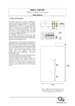
4. Connector pin assignments
The electrical port pin assignments (see table 5) are
such that similar ports of different units may be
connected back to back with reversed cable (RS232 interfaces excepted). See figure 5 for the pin
numbering convention used.
Pin
1
2
3
4
5
6
7
8
RS-485 line termination: Line termination impedance
of interfaces D1 and D3 may be set to low (120 Ω)
using dip switch 6 of bank S1 and S2, respectively
(see table 3). Default is high impedance.
Audio port impedance: Audio input impedance in the
ADS 1200 can be set by moving jumpers A (for audio
interface A1) and/or B (for interface A2) on the upper
circuit board (fig. 2). A jumper on pins 1-2 will select
high impedance for that port (default); shorting pins 2
and 3 will lower the audio input impedance to 600
Ohms.
Port 1 (2)
Audio in +
Audio in GND
CC1out b
CC1in (ref. to GND)
CC1out a
Audio out Audio out +
Pin
1
2
3
4
5
6
7
8
Port 3 (4)
RS-485/422 in + **
RS-485/422 in - **
RS-232 in
RS-232 out
GND
GND
RS-485/422 out RS-485/422 out +
Table 5. Electrical port pin assignments
** see note Figure 5
1
3b) Installation
Provide the units with power and connect appropriate
cabling (twisted pair for long electrical links).
Through-connecting the signal ground lines is
recommended. If SYNC problems occur after
powering up, please check the optical link first.
8
1
8
AUDIO1 IN +
AUDIO1 IN GND
CC1 OUT B
CC1 IN (ref. GND)
CC1 OUT A
AUDIO1 OUT AUDIO1 OUT +
RS-485/422-1 IN + **
RS-485/422-1 IN - **
RS-232-1 IN
RS-232-1 OUT
GND
GND
RS-485/422-1 OUT RS-485/422-1 OUT +
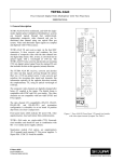
Figure 5.
Socket pin assignments. The second port (A2/CC2) is
similar in layout to port A1/CC1/ while the downmost
port (D3/D4) is similar to the third (D1/D2).
Input connector pins marked ** also work as outputs in
2-wire mode (see text).
3
5. Technical specifications
ADS type >
6. Safety, EMC, ESD
1200 TRX/
1210 TRA-TRB
General
1240 TRX/
1250 TRA-TRB
Property ↓
Optical
Wavelength(s)
850/850-1300
1310/1310-1550 nm
Fibre
MM (2x/1x)
SM (2x/1x)
dB, km
22, 44
Budget, distance 15 (19)1), 5 (6)1)
Audio
Channels
Bandwidth
I/O level
SNR
THD
I/O impedance
1 at port 1, 1 at port 2 (both full duplex)
40 to 15k
Hz
0 (+6 max)
dBV
>62dBA
<1 (at nom. level)
%
in: 600 or >50k/out: <50 balanced Ω
Contact closure
Channels
Activation at
Input
Output
Output switch
1 at port 1, 1 at port 2 (both full duplex)
V
0.75 (<1.5 kΩ)
+5 V pull-up, 10 kΩ
Normally open, fail-safe
2A @ 30 VDC
UL/IEC/EN 60950-1: General safety requirements
Data (port 3; port 4)
Channels per
port
Data format
Data rate (per
channel)
RS-232; RS-485 2) (2-wire, 4-wire,
RS-422 or 20 mA digital CL)
Asynchronous, serial
DC to 64
kbit/s
Management
Front panel
LEDS
SNM
management
variables
see text
Voltage, module temp., alarm
status, configuration et al
Environmental and Safety
Operating temp.
Humidity (max.)
Electrical safety
UL recognition file
Laser safety
EMC immunity
EMC emission
-40 to 74
<95 (no condensation)
AL / IEC / EN 60950-1
E242498
IEC 60825-1, IEC 60825-2
EN 55024, EN 50130-4,
EN 61000-6-2
EN 55022 (Class B)
FCC 47 CFR 15 (Class B)
Mechanical
Opt. connectors
Data, audio,
CC connectors
Dimensions
Weight (appr.)
1)
2)
3)
4
+/-15 (rack), 12 external (SA)
This optical equipment contains Class 1M lasers or LEDs
and has been designed and tested to meet IEC 608251:1993+A1+A2 and IEC 60825-2:2004 safety class 1M
requirements.
Optical equipment presents potential hazards to testing and
servicing personnel owing to high levels of optical radiation.
When using magnifying optical instruments, avoid looking
directly into the output of an operating transmitter or into the
end of a fibre connected to an operating transmitter, or there
will be a risk of permanent eye damage. Precautions should
be taken to prevent exposure to optical radiation when the
unit is removed from its enclosure or when the fiber is
disconnected from the unit. The optical radiation is invisible
to the eye.
Use of controls or adjustments or procedures other than
those specified herein may result in hazardous radiation
exposure.
The installer is responsible for ensuring that the label
depicted below (background: yellow; border and text: black)
is present in the restricted locations where this equipment is
installed.
o
C
%
W
W
ST (MM) 3), FC (SM) 3)
for RJ45 plug (4x)
190x128x35 (7TE)
450
The equipment described in this manual has been
designed and tested according to the UL/IEC/EN 60950-1
safety requirements.
If there is any doubt regarding the safety of the equipment, do
not put it into operation. This might be the case when the
equipment shows physical damage or is stressed beyond
tolerable limits (e.g. during storage and transportation).
Before opening the equipment, disconnect it from all power
sources. The equipment must be powered by a SELV*) power
supply.
When this unit is operated in extremely elevated temperature
conditions, it is possible for internal and external metal
surfaces to become extremely hot.
Optical safety
Powering
Power cons.
Power voltages
The safety information contained in this section, and on
other pages of this manual, must be observed whenever this
unit is operated, serviced, or repaired. Failure to comply with
any precaution, warning, or instruction noted in the manual
is in violation of the standards of design, manufacture, and
intended use of the unit.
Installation, adjustment, maintenance and repair of this
equipment are to be performed by trained personnel aware of
the hazards involved. For correct and safe use of the
equipment and in order to keep the equipment in a safe
condition, it is essential that both operating and servicing
personnel follow standard safety procedures in addition to the
safety precautions and warnings specified in this manual, and
that this unit be installed in locations accessible to trained
service personnel only.
Optelecom-NKF assumes no liability for the customer’s
failure to comply with any of these safety requirements.
mm
g
With 62.5 μ optical fibre
Manchester/biphase compatible
On one-fibre models, other connectors may be fitted on request
Hazard Level 1M
Table 6. ADS 1200 series, technical specifications
The locations of all optical connections are listed in the
Indications and Connectors section of this manual.
Optical outputs and wavelengths are listed in the Technical
Specifications section of this manual.
4
EMC
If system components, such as cabling (e.g. coaxial cable,
data/audio/cc wiring) and/or the units, are used outdoors,
ensure that all electrically connected components are
carefully earthed and protected against surges (high voltage
transients caused by switching or lightning).
The equipment has been tested and found to meet the CEregulations relating to EMC, and complies with the limits for
a Class B device, pursuant to Part 15 of the FCC rules. These
limits are designed to provide reasonable protection against
interference to radio communications in any installation. The
equipment generates, uses and can radiate radio frequency
energy; improper use or special circumstances may cause
interference to other equipment or a performance decrease due to
interference radiated by other equipment. In such cases, the user
will have to take appropriate measures to reduce such
interactions between this and other equipment.
Any interruption of the shielding inside or outside the equipment
could cause the equipment to be more prone to fail EMC
requirements.
Non-video signal lines must use appropriate shielded CAT5
cabling (S-FTP), or at least an equivalent.
ESD
Electrostatic discharge (ESD) can damage or destroy
electronic components. Proper precautions should be
taken against ESD when opening the equipment.
*)
SELV: conforming to IEC 60950-1, <60VDC output, output
voltage galvanically isolated from mains. All power supplies or
power supply cabinets available from Optelecom-NKF comply
with these SELV requirements.
©Optelecom-NKF 2006
Version 021403-2
ADS1200 (MW03SP-2)
5