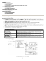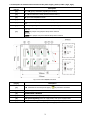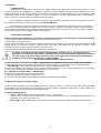
1
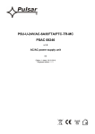
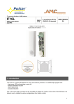
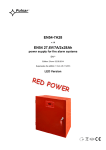
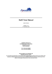
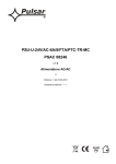
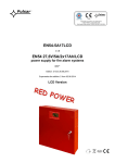
PSU-S/H-12V/S-4A/8/FTA/PTC-MC
PSDC08124
v.1.1
Stabilised, impulse power supply unit
EN
Version: 2 dated 18.01.2011
Replaces edition: 1 dated 26.03.2010
CONTENTS:
1. Technical description.
1.1. General description
1.2. Block diagram
1.3. Description of elements and connectors of the power supply
1.4. Technical parameters
2. Installation.
2.1. Requirements
2.2. Procedure of installation
3. Signalling the operation of power supply.
3.1. Optical signalling
3.2. Technical output
4. Service and operation.
4.1. Short-circuit protection
4.2. Overload protection
4.3. Maintenance
1. Technical description.
1.1. General description.
Stabilized power supply power supply is used for supply devices which require stabilised voltage of 12 V DC (12.0V÷15.0V DC).
Basic features of the power supply:
•
8 outputs protected independently with fuses: F 500mA or PTC, failure (short-circuit) within the circuit of any of the
outputs will result in burnout of the safety device insert or actuation of the PTC and isolation of the circuit from DC (+U)
supply.
•
optical work signalling informing about the condition of outputs and/or failure.
•
AW technical output informing about output failure (activity of the SCP), used for remote control of the activity.
•
protection: short-circuit protection (SCP), overload protection (OLP), over voltage protection (OVP)
•
regulation of the output voltage: in case of installation, where significant drops in voltage in effective resistance of
receiver supply cables can occur, it is possible to correct the voltage value with the help of P1 potentiometer (12.0V÷15.0V
DC).
•
the power supply uses the modern module of the impulse power supply.
•
metal casing (colour – RAL 9003) with signalling panel.
Information about types:
Model
PSDC 04122
PSU-S/H-12V/S2A/4/FTA/PTC-MC
PSDC 04124
PSU-S/H-12V/S4A/4/FTA/PTC-MC
PSDC 16128
PSU-S/H-12V/S8A/16/FTA/PTC-MC
Description
Stabilised (impulse) power supply, with overall current efficiency of 2A and output voltage of 12
V DC. Equipped with AUX1÷AUX4 output condition signaling panel. IP20 metal casing with
signaling panel, equipped with TAMPER microswitch.
Stabilised (impulse) power supply, with overall current efficiency of 4A and output voltage of 12
V DC. Equipped with AUX1÷AUX4 output condition signaling panel. IP20 metal casing with
signaling panel, equipped with TAMPER microswitch.
Stabilised (impulse) power supply, with overall current efficiency of 8A and output voltage of 12
V DC. Equipped with AUX1÷AUX16 output condition signaling panel. IP20 metal casing with
signaling panel, equipped with TAMPER microswitch.
1.2. Block diagram (fig.1).
Fig.1. Block diagram of the power supply.
2
1.3. Description of elements and connectors of the power supply ( table 1, table 2, fig.2, fig.3).
Element No.
[Fig. 2]
Description
[1]
L1…..L8 (green) LED diodes (signalling fuse activity)
[2]
F1….F8 fuse element of safety devices in AUX circuits (+)
[3]
IN input of the LB8/AW fuse block
[4]
AUX1…. AUX8 outputs, common COM clamp (-)
[5]
LAW (red) diode signalling failure of one of the outputs (activation of a safety device)
[6]
AW output signalling failure of one of the outputs, OC type (normal L status, failure: hi-Z)
Jumper of the change in PTC/fuse-element safety device type
Fx Fx.x
[7]
Fx jumper used, polymer safety device selected
Fx Fx.x
Fx.x jumper used, fuse-element safety device selected
Table 1. LB8/AW elements– fuse block.
Fig.2. View of the LB8/AW fuse block.
Element No.
[Fig. 3]
Description
[1]
L-N connection of 230 V AC power supply,
[2]
F fuse in supply 230 V AC circuit
[3]
POWER SUPPLY MODULE
[4]
P1 potentiometer, regulating the output voltage
[5]
LED optical signalling of the DC supply status, main power supply module
[6]
LB8/AW fuse block, with supply outputs and optical signalling
PE protection connection
Table 2. Elements of the power supply.
3
Fig.3. View of the power supply.
4
1.4. Technical parameters:
- electrical parameters (table3)
- mechanical parameters (table4)
- user safety (table5)
- operation parameters (table6)
Electrical parameters (table 3).
Supply voltage
Supply frequency
S power supply power
Power consumption
Output voltage
Output voltage maintenance time
Range of voltage setting
Ripple voltage
Output power
Short-circuit protection SCP
Overloading protection OLP
Over-voltage protection OVP
Technical outputs:
- AW output signalling failure of fuse burning) of the
LB8/AW fuse block (activation of the SCP)
F fuse
F1÷F4 fuse
88-264 V AC, 125-373 V DC
47÷63Hz or DC
60W max.
0.8 A /230 V AC (40A/ 230 V AC “cold start”)
12.5V DC nom.
60 ms
12.0V÷15.0 V DC (-5%/+5%), 1x P1 regulation
120 mV p-p max.
8x 0.5A or 4x F 1.0A (fuses from the set) ΣI= 4.0A
LB8/AW fuse block
8 x F 0.5A fuse-element safety device or PTC 1A
or 4xF 1A (fuses from the set)
POWER SUPPLY MODULE
110% ÷ 150% of the power supply power
electric current limitation, automatic return after the failure
has ceased
110% ÷ 150% of the power power supply
electric current limitation, automatic return after the failure
has ceased
17.25 V÷ 20.25V disconnecting the output voltage, manual
restoring – disconnection of AC supply
- type OC, 50mA max.
normal status: L level (0 V)
failure status: hi-Z level
T 2.5A/250V
F 0.5A/250V or PTC 0.5A (manual selection)
Mechanical parameters (table 4).
Casing dimensions
230 x 230 x 50 (WxHxD) , with casing: (235 x 235 x 58)
Fixing
198 x 196 x Φ 6 (WxH)
Net/gross weight
1.40/1.60 kg
Colour of the casing
RAL 9003
Closing
Cylindrical screw: from the front of the casing
Connections
230 V AC supply: Φ0.63÷2.05 (AWG 22-12)
Outputs: Ф0.51÷2.05 (AWG 24-12)
LB8/AW : Ф0.51÷2.05 (AWG 24-12)
Remarks
The casing is equipped with distance from the mounting basis in order to guide the wiring
system, convection cooling.
User safety (table 5).
PN-EN 60950-1:2004 protection class
PN-EN 60529: 2002 (U) protection degree
Insulation electric strength:
- between the input (network) circuit and output circuits of the power supply
(I/P-O/P)
- between the input circuit and the PE protective circuit (I/P-FG)
- between the output circuit and the PE protective circuit (O/P-FG)
Insulation strength:
- between the input circuit and the output or protective circuit
I (first)
IP20
3000 V AC min.
1500 V AC min.
500 V AC min.
100 MΩ, 500 V DC
Opaeration parameters (table 6).
-10ºC...+50ºC
-25ºC...+60ºC
10%...90% without condensation
unacceptable
unacceptable
unacceptable
According to PN-83/T-42106
Operating temperature
Storing temperature
Relative humidity
Vibrations during operation
Surges during operation
Direct exposure to sunlight
Vibrations and surges during transport
5
2. Installation.
2.1 Requirements.
Stabilized power supply shall be mounted by the qualified installer having appropriate (required and necessary for a given
country) permissions and qualifications for connecting (operating) 230V/AC installations and low-voltage installations. The device
should be mounted in closed rooms, according to II environmental class, with nominal air humidity (RH = 90%, maximum, without
condensation), and the scope of temperature within -10 °C and +50 °C (table 6). The power supply should work in vertical position, in
order to ensure free convection airflow by ventilation holes in the casing.
Before installation is started, the balance of the power-supply load shall be performed.. During normal operation the sum of
the currents consumed by the receivers cannot exceed I=4A (P=60W max).
Because the power supply was designed for continuous work, it is not equipped with supply switch, hence it is essential to
ensure proper overload protection in the supply circuit. It is also necessary to inform the user about the manner of disconnecting the
power supply from the network supply (usually by isolating and determining proper fuse element in the fuse box). Electric installation
should be performed according to binding standards and regulations.
2.2 Procedure of installation.
1. Before initiating the installation it is necessary to ensure that the voltage in the 230 V power circuit is disconnected.
2. Mount the power supply in the selected place and guide connecting conductors.
3. Take off the fuse from power circuit
4. Connect the power cables (~230 V AC) with L-N power supply terminals. Connect the earth conductor to the clamp marked with
earthing symbol. The connection should be performed with 3-core cable (with yellow-green PE protecting conductor). Power
conductors should be connected to proper terminals, through seal wire.
Power conductors should be connected to proper terminals, through seal wire.
The circuit of the shock protection shall be performed with a particular care, i.e. the yellow and green
protection wire of the power cable shall be connected from one side to the terminal marked by the symbol of
in the casing of the power-supply. Operation of the power-supply without the properly made and fully
operational circuit of the shock protection is UNACCEPTABLE!
It can result in failure of devices and electric shock.
5. Connect the cables of consumers to the AUX1…..AUX8 terminals on LB8/AW fuse block with configuration of 8x0.5A.
6. When necessary, connect device cables (alarm exchange, controller, signaller, etc.) to technical outputs of the power supply:
- AW (LB8/AW) output signalling the activity of the fuse (output of the LB8/AW fuse block).
7. In case of installation, where significant drops in voltage in effective resistance of receiver supply cables can occur, it is possible to
correct the value of voltage with the help of P1 potentiometer (12.0V÷15.0V DC).
P1 – regulation of voltage in AUX1…..AUX8 outputs.
8. Place the fuse in the power circuit and connect the supply.
9. Check optical signalling of the power supply operation.
10. Close the casing after installing and verifying the correctness of the power supply activity.
3. Signalling the operation of power supply.
The power supply is equipped with optical signalling the status of operation. Presence of voltage on power supply outputs is signalled
by illumination of green LED diodes on the frontal panel of the device. Failure is signalled by red LED diode [!] AW. Condition of the
power supply may be controlled remotely by AW technical output.
3.1 Optical signaling (fig.4).
•
LED L1….L8 green diodes signal the supply status on AUX1…..AUX8 outputs.
In case of loss of voltage on the output (burnout of the fuse/ activation of the PTC), appropriate LED diode stops to be
illuminated (L1 for AUX1, L2 for AUX2, etc.).
•
LED [!] AW red diode indicates failure of at least one AUX output (number of the output is signalled by the green diode).
6
Fig.4. View of the power supply panel.
3.2 Technical output.
AW output signals the failure of the fuse (output of the LB8/AW fuse block).
During the proper operation of LB8/AW fuse block AW technical output is on the mass potential (-), whereas in case of
damaging one of the fuses, the output shall be disconnected from the mass (Hi-Z status). This status is also signalled by the red LAW
diode on the LB8/AW fuse block.
4. Service and operation.
4.1 Procedure in case of short-circuit (SCP activity) of the power supply output.
Outputs of the AUX1÷AUX8 power supply of the LB8/AW fuse block are protected against short-circuits with fuse-element
safety device (inserts) or PTC.
If fuse-element safety device was chosen, then in case of failure it is necessary to exchange the fuse element (compliant with
the original).
If PTC polymer fuses protection was chosen, then automatic disconnection of the output voltage was signalled by switching
off the green diode. It is then necessary to disconnect the load from the power supply output for the period of about 1 min.
4.2 Procedure in case of overload (OLP activity) of the power supply.
In case of loading the power supply with current exceeding 4A (110% ÷ 150% P) the output voltage shall be automatically
disconnected, automatic restoration after removing the failure (overload).
4.3 Procedure in case of initiation of OVP system of the power supply.
In case of initiating the OVP system, it is necessary to disconnect the power supply from the network for about 1 minute.
4.4 Maintenance.
All maintenance procedure may be performed after disconnecting the power supply from the power network. The power supply unit
does not require performing any special maintenance procedures, however, in case of significant drop of the dustiness, it is only
essential to remove the dust from the interior with the help of compressed air. In case of changing the fuse it is essential to use
substitutes compliant with the original parts.
7
WEEE MARKING
The used electric and electronic device may not be thrown out together with common household wastes.
According to WEEE directive, binding within the EU, in case of used electric and electronic devices separate
means of utilization should be utilized.
GENERAL WARRANTY CONDITIONS
1. Pulsar K. Bogusz Sp.j. (producer) provides two-year quality warranty for the device, counting from the date of sale indicated on the bill of sale.
2. In case when there is no bill of sale when filing the claim, three-year warranty period shall be counted from the date when the device was manufactured.
3. Warranty shall cover free repair or provision of functional equivalent (the producer shall select the equivalent) of the faulty device due to reasons lying in the
domain of the producer, including production and material faults, unless these faults have been filed within the warranty period (point 1 and 2).
4. Device falling under warranty period should be delivered to the point, where it was purchased or directly to the seat of the producer.
5. Warranty covers complete devices with written description of the fault on properly filled claim application form.
6. When a claim shall be positively considered, the Producer shall be obliged to realise warranty repairs in the shortest possible time, however this period of
time should not extend 14 working days from the date when the device was delivered to the producer’s service point.
7. Repair period, of which mention has been made in point 5 may be prolonged in case of lack of technical possibilities to perform the repair and in case of
device conditionally accepted to the service point, as the claimant did not meet the warranty conditions.
8. All service activities resulting from the warranty shall be performed solely within the service point of the producer.
9. Warranty does not cover faults of the device resulting from:
- reasons not lying within the power of the producer,
- mechanical failures,
- improper storage and transport,
- usage not compliant with the user manual or the anticipated use of the device,
- random events, including atmospheric discharges, power line failure, fire, flooding, influence of high temperatures and chemical agents,
- improper installation and set up (not compliant with principles included in the user manual).
10. Statement of performing changes in construction or repairs performed outside the service point of the producer or when the serial numbers or warranty
stickers on the device were anyhow damaged shall result in the loss of warranty rights.
11. Responsibility of the producer towards the purchaser shall limit to the value of the device, settled according to the determined wholesale price suggested by
the producer from the date of purchase.
12. Producer shall bear no responsibility for faults resulting from damaging, improper activity or impossibility to use the device, especially when the above
results from non-observance of recommendations and requirements included in the user manual or use of the device.
Pulsar K. Bogusz Sp.j. /Registered partnership/
Siedlec 150,
32-744 Łapczyca, Poland
Tel. (+48) 14-610-19-40, Fax. (+48) 14-610-19-50
e-mail: [email protected], [email protected]
http:// www.pulsar.pl
8