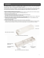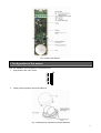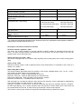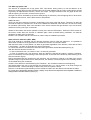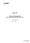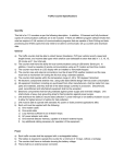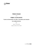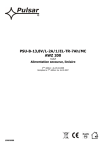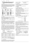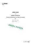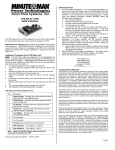
1
The exclusive distributor of AMC products
IF16L
Digital curtain detector
(dual PIR)
CODE
IF16L
In accordance with the
EN 50131-2-2 standard
USER MANUAL
EN
Edition: 1 from 10.03.2014
Supercedes the edition: -----------
1. Introduction
The IF16L is a curtain PIR detector for doors and windows protection. It is additionally equipped with:
- high power LED (soft switching on and off)
- direction detection function
- alarm delay circuit
- acoustic indication
Due to the wide angle coverage and the possibility of limiting the rotation of the width of the PIR beam, the
detector can be installed in various configurations (top, bottom or side).
1
2. Installation
The detector should be mounted by a qualified installer, holding relevant permits and licenses (applicable
and required for a given country) for Intrusion Detection Systems.
Follow the basic rules for the installation of Intrusion Detection Systems (pay attention, among others, not to
soil or damage the pyroelectric element). The latch system used in the enclosure of the detector eliminates
the need for screw connections, so that the detector installation is simple and does not take much time.
Perform the following steps to mount the detector:
1. Open the detector by releasing (using thin screwdriver) the latch in the lower part of the enclosure (Fig.1a).
2. Remove the PCB from the base by releasing the locking clip (Fig. 1b).
3. Drill a hole to lead the cable (Fig. 1b).
4. Lead the cables through the hole and connect them to the terminal strip (Fig.2).
Description of terminals is presented later in this manual.
5. Mount the lower part of the sensor housing with two screws in the locations shown in Fig. 1b. Make sure
that the screw is inside the socket and screws do not touch the PCB.
6. Configure the detector (information on the control elements with a description of the available functions
can be found in the following pages).
7. Close the lid of the sensor.
8. Connect the supply voltage and wait until the LED of the sensor stops flashing.
Caution! After connecting, the detector needs about 40 seconds for start and calibration. During this time,
the alarm cannot be activated. The sensor can be activated again five seconds after each activation.
Fig. 1a. The enclosure of the detector.
Fig. 1b.The enclosure base of the detector.
2
Fig. 2 PCB of the detector.
3. Configuration of the sensor
Both the installation and configuration of the sensor use:
1. Eight-position ON / OFF switch.
2.
Floating beam separator and removable lens.
Fig. 3 Floating beam separator and removable lens.
3
DIP switch
DIP1
Acoustic indication (speaker)
DIP2
Optical indication (red LED)
DIP3
Sensor range
DIP4, DIP5 - type of sensor operation
(immediate action / alarm delay)
DIP6
High power LED
DIP7
Direction detection
DIP8
Setting the alarm direction (Fig.2)
OFF
off
ON
on
off
on
2m
3,5m
immediate action
DIP4-OFF, DIP5-OFF
30 seconds alarm delay
DIP4-ON, DIP5-OFF
one and half minute alarm delay
DIP4-OFF, DIP5-ON
two minute alarm delay
DIP4-ON, DIP5-ON
off
on
alarm from all directions
alarm from one direction*
1 → 2 - alarm
2 → 1 - alarm
* For correct use of the direction detection function, properly set up the lens and adjust the beam separator in addition to
setting the DIP7 and DIP8 switches (see Fig. 4).
Description of functions contained in the table.
Acoustic indication (speaker) – DIP1
The sensor has a built-in speaker for acoustic indication Acoustic signaling is activated with the DIP1 dip
switch. The type of emitted sound varies depending on the direction. The acoustic signal is also used for
signaling other events described below.
Optical indication (red LED) – DIP2
The sensor is equipped with a red LED for alarm signaling and informing about other events including alarm
delay.
Sensor range - DIP3
Selection of sensor range in order to adapt the beam to the protected area. It is possible to set a value of 2
meters or 3.5 meters.
Alarm delay (DIP 4 - DIP5)
This feature enables alarm delay after the activation of the sensor (available delays: 30 s, 1.5 min., 2 min.).
Use the DIP4 or DIP5 switches to set the delay time:
DIP4-ON, DIP5-OFF - a delay of approximately 30 seconds,
DIP4-OFF, DIP5-ON - a delay of approximately one and half minute,
DIP4-ON and DIP5-ON – delay time adds up and is about 2 minutes,
DIP4-OFF and DIP5-OFF – immediate action of the sensor.
With this feature on, the detector starts the timer after the first activation, which is indicated by rapid flashing
of the red LED (Note: The LED must be on, DIP # 2 ON).
During the countdown, of the set time - the sensor is blocked and cannot be activated. After the countdown,
the LED stops flashing). If is no further activation within 20 seconds, the sensor will be reset. If the sensor will
be activated within 20 seconds, an alarm will be generated (NC contact will be opened).
This function is used to gain access to the protected area without having to disarm the system.
4
The DIP6 high power LED
The detector is equipped with a high power LED. This allows, among others, to use the detector as an
emergency lighting lamp (remotely activated when the terminal marked with the "bulb" symbol will be shorted
to ground). To implement this function, use the OC output. The light activated in this way lights all the time
until the opening of the "bulb" contact from the ground.
The light can also be activated by the sensor itself (during its activation), then the lighting time is 40 seconds.
To implement this function, set the DIP6 switch to ON position.
Additional notes:
Turning on the light causes an increase in temperature in the area of the PIR sensor. Therefore, for about 20
seconds the sensor is switched off in order to re-calibrate the thresholds. After this time, the sensor is ready
for operation (LED mode). Each new activation of the sensor extends the light duration up to 40 seconds,
and alarm recovery time up to 10 seconds.
Thanks to this solution the sensor operates correctly even with the LED lamp on. When the LED is turned off,
the sensor needs about 20 seconds to calibrate again. When activated during calibration, the detector
generates an alarm, after 30 seconds.
Caution! The activation must be continuous in order to stop the calibration procedure.
Alarm direction detection (DIP7, DIP8)
The IF16L detector is equipped with the direction detection function. With this feature on, it is possible to
define when an alarm is to be generated. To activate the function, use the DIP7 switch.
With the DIP7 switch in OFF position, an alarm is generated regardless of the direction, while with the DIP7
in ON position – an alarm is generated only from one direction.
To choose the direction from which the alarm should be generated, use the DIP8 switch (see Fig. 6)
With the direction detection function on:
- in case of activation from „no entrance” area - an alarm is generated,
- in case of activation from „free entrance” area the detector is blocked and starts 2 minutes countdown,
which is indicated by the slow blinking of the LEDs (the last 10 seconds are indicated by faster blinking of the
LED and acoustic signal).
During aforementioned two minutes from the activation, the movement of objects in the field of the sensor
operation might not generate an alarm. After this time, the detector is reset and goes into the standby mode if
not activated during the countdown.
Caution! If the detector is activated during the countdown - the countdown starts from the beginning.
This feature allows the user to exit through the protected door, e.g. onto a terrace or to peep through the
protected window - without activating an alarm even when the system is armed.
However, if the direction (first activation) is from outside to inside, then the detector will activate the alarm.
For correct use of the direction detection function, properly set up the lens and adjust the beam separator in addition to
setting the DIP7 and DIP8 switches (see Fig. 4).
5
Fig. 4 Beam forming by setting the separator and putting the lens on.
Fig. 5 Example of sensor installation.
6
4. Technical data
IF16L
Power supply
Power consumption: Alarm / Standby
Current consumption with high power LED on
Sensor range
Operating angle
PIR sensor
Lens
Alarm signaling time
Programmable alarm delay
Tamper protection (opening of the detector)
Maximum load of the contacts of the relay
Maximum load of the contacts of the tamper
Operating temperature
Storage temperature
Electromagnetic immunity (radio frequency interference) RFI
LED (walk test)
High power LED (additional lightning)
In accordance with the standard
Protection class
Enclosure material
Dimensions (H x W x D)
Pet immunity
9÷15VDC
12,mA/23mA@13,8VDC
260mA
do 2m / 3,5m
11° (no beam separation 165°)
2 elements
6 areas in 1 level
4s
YES
YES
100mA@40VDC / 16Ω
40mA@30VDC
-25°C÷55°C
-25°C÷60°C
10V/m (20MHz-1000MHz)
YES
YES
EN 50131-2-2 Grade 2
IP42
ABS
130mm x 37mm x 30mm
NO
In accordance with the standards:
CEI EN 50131-2-2
Grade 2
Class 2
RoHS
Additional information
The manufacturer takes no responsibility for the defects that result from the damaging, malfunctioning or
inability to operate the equipment especially when resulting from failure to comply with the recommendations
and requirements contained in the manual.
It is necessary to periodically test the signaling device. The majority of Intrusion Detection Systems
indicates malfunctioning of the signaling devices and informs the user with an appropriate message on the
LCD keypad or LED light on the LED display. In case of such situation, the system installer shall be
immediately notified. Testing and control methods of Intrusion Detection Systems are specifically determined
by the installer.
The IF16L detector was made in accordance with the requirements of the EEC and 99/5/CE directives.
The Declaration of Conformity is available at www.pulsar.pl.
7
WEEE LABEL
Waste electrical and electronic equipment must not be disposed of with normal household
waste. According to the European Union WEEE Directive, waste electrical and electronic
equipment should be disposed of separately from normal household waste.
GENERAL WARRANTY CONDITIONS
1. Pulsar K. Bogusz Sp.j. (manufacturer) grants a two-year quality warranty for the equipment, starting from the production date.
2. The warranty includes free-of-charge repair or replacement with an appropriate equivalent (selected by the manufacturer) if
the malfunction is due to the manufacturer. It includes manufacturing or material defects, provided that such defects have been
reported within the warranty period (point.1).
3. The equipment subjected to warranty should be brought to the place of purchase or directly to the main office of the
manufacturer.
4. The warranty applies to complete equipment, accompanied by a properly filled warranty claim with a description of the defect.
5. Should the claim be accepted, the manufacturer is obliged to provide warranty repairs, at the earliest convenience, however not
later that within 14 days from the delivery to the service centre of the manufacturer.
6. The repair period mentioned in point 5 may be prolonged, if there are no technical possibilities to carry out the repairs, or if the
equipment has been conditionally accepted, due to the breaking warranty terms by the claimant.
7. All the services are carried out at the service centre of the manufacturer, exclusively.
8. The warranty does not cover the defects of the equipment, resulting from:
- reasons beyond the manufacturer's control,
- mechanical damage,
- improper storage and transport,
- use that violates the operation manual or equipment’s intended use,
- fortuitous events, including lightning discharges, power failures, fire, flood, high temperatures and chemical agents,
- improper installation and configuration (failure to follow instruction).
9. The warranty is void in case of construction changes and repairs carried out by any unauthorized service center or in case of
damage or modifications to warranty stickers and serial numbers.
10. The liability of the manufacturer towards the buyer is limited to the value of the equipment determined according to the
wholesale prices suggested by the manufacturer on the day of purchase.
11. The manufacturer takes no responsibility for the defects that result from the damaging, malfunctioning or inability to operate
the equipment especially when resulting from failure to comply with the recommendations and requirements contained in the
manual.
The exclusive distributor of AMC products:
Pulsar K. Bogusz Sp.j.
Siedlec 150, 32-744 Łapczyca, Poland
Phone (+48) 14-610-19-40, Fax (+48) 14-610-19-50
E-mail: [email protected], [email protected]
www.pulsar.pl, www.zasilacze.pl
8