1
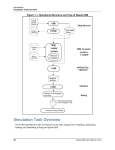
VSIM Modem and
Telephony Simulator User
Manual
Miller Engineering Services, Inc.
E-mail: [email protected]
Web: www.mesi.net
1
VSIM USAGE....................................................................................................................................... 3
1.1
VSIM COMMAND LINE OPTIONS .................................................................................................... 3
1.1.1
-v Option................................................................................................................................. 4
1.1.2
-f[filename] Option................................................................................................................. 5
1.1.3
-o[filename] Option................................................................................................................ 5
1.1.4
-D[filename] Option ............................................................................................................... 6
1.1.5
-NUM[samples] ...................................................................................................................... 6
1.1.6
-m[mode], -M[mode] Options ................................................................................................ 6
1.1.7
-n[ratio] Option...................................................................................................................... 6
1.1.8
-t[power] Option..................................................................................................................... 6
1.1.9
-twist[ratio] Option ................................................................................................................ 6
1.1.10 -T[ratio] Option...................................................................................................................... 6
1.1.11 -r[rate] Option........................................................................................................................ 7
1.1.12 -c[filename] Option ................................................................................................................ 7
1.1.13 -i[type] Option........................................................................................................................ 7
1.1.14 -d[dir] Option ....................................................................................................................... 12
1.1.15 -p Option............................................................................................................................... 12
1.1.16 -w Option .............................................................................................................................. 12
1.1.17 -l[delay] Option.................................................................................................................... 12
1.1.18 -g[level], -G[level] Options.................................................................................................. 12
1.1.19 -j[freq], -J[level] Options..................................................................................................... 12
1.1.20 -s[offset] Option ................................................................................................................... 12
1.1.21 -BER[filename] Option......................................................................................................... 13
1.1.22 -ACQ Option......................................................................................................................... 13
1.1.23 -L[length] Option ................................................................................................................. 13
1.1.24 -E[length] Option ................................................................................................................. 13
1.1.25 -YA[delay] and YC[delay] Option....................................................................................... 14
1.1.26 -NA[delay] and NC[delay] Option ...................................................................................... 14
1.1.27 -F[delay] Option................................................................................................................... 14
1.1.28 -ERLnearA[gain] Option...................................................................................................... 14
1.1.29 -ERLfarA[gain] Option ........................................................................................................ 15
1.1.30 -ERLnearC[gain] Option...................................................................................................... 15
1.1.31 -ERLfarC[gain] Option ........................................................................................................ 15
1.1.32 -C[type] Option .................................................................................................................... 15
1.1.33 -O[freq][%] Option.............................................................................................................. 16
1.1.34 -h[freq] and -H[ratio]Options.............................................................................................. 16
1.1.35 -S Option............................................................................................................................... 16
1.1.36 -P Option .............................................................................................................................. 16
1.1.37 -EC_plot_taps Option........................................................................................................... 16
1.1.38 -V Option .............................................................................................................................. 17
1.1.39 -IQ Option ............................................................................................................................ 17
1.1.40 -nographics Option............................................................................................................... 17
1.2
VSIM SIMULATION OPTIONS ........................................................................................................ 17
1 VSIM Usage
The VSIM simulator runs under a DOS window that switches to full screen to support
VGA graphics mode. It is a DOS command-line driven program that accepts a variety of
command-line configurations and run-time controls that are described in the following
sections. VSIM implements a two-channel telecom simulation that emulates a CALL
channel and an Answer channel so that fax and data modems, call progress, dual tone
digit signaling, and miscellaneous telephony tones can be evaluated. VSIM can be
configured to display and/or dump to file the Answer or CALL side receiver()
processor’s operational status, and the user can toggle the display and file mode between
CALL and Answer during execution. The channel simulation includes a variety of
common telephony impairments that can be selectively enabled at run time and altered
during execution. The graphical display is a crude emulation of a 2-channel storage
oscilloscope with dual-trace and X-Y plot modes, again selectable at run time and during
execution. File I/O includes a general run-time continuous dump in a file called simply
“x”, and a time-tagged log of all transmitter() and receiver() state_ID’s for both CALL
and Answer sides in a file called “states.dat”. VSIM can optionally accept input for a
specified sample file (8 kHz samples, one per line, ASCII HEX format) so that users can
digitize live-line signals, feed them to VSIM (which implements exactly the same
algorithms as the DSP ports), and readily observe the modem’s behavior off-line. The
VSIM channel model provides a complete and accurate method for Bit Error Rate (BER)
and Acquisition (ACQ) testing under a variety of impairments in an automated fashion In
BER and ACQ modes, the SNR is automatically swept and the BER, BLER (Block Error
Rate), and acquisition statistics are logged to “ber.dat”.
1.1 VSIM Command Line Options
The general form for execution of the VSIM simulator under MS-DOS is:
VSIM –option –option –option …
Where the –options are:
-v[modem] => modem type: (default is -v29)
8, 17, 17TEP, 21, 22, 23, 23B, 26, 26A, 26B, 26P, 27, 27TEP,
29, 29TEP, 32, 32bis, 34, bell103, bell103F1, bell103F2,
bell202,
noise, tone, CED, ECSD, DTMF, R1, R2F, R2B, CAS, CID, CNG,
dialtone, ringback, busy, reorder
-f[filename] => file input
-o[filename] => output IF to file, default='rxif.dat'
-D[filename] => data file input, ASCII hex, one symbol per line
-NUM[samples] => num_samples, frame size (8kHz samples), default=20
-m[mode] => Tx->mode, -M[mode] => Rx->mode
-n[ratio] => Signal-to-Noise Ratio (dB), default=100 dB
-t[power] => CALL Tx power (dBm0), default=-16 dBm0
-T[ratio] => answer/call Tx power ratio (dB), default=0 dB
-twist[ratio] => high/low tone Tx power ratio (dB), default=0 dB
-r[rate] => data rate: 1200 through 14400 (bits/sec.), default=9600)
-c[filename] => plot constellation or file
-i[type] => gain distortion impairment: (default=0)
0=none, 1=AT&T spec, 2=PSTN typical, 3=CONUS_MV, 4=CONUS_PV
-d[dir] => direction: a=answer c=call, default=a
-p => enable pause between modem calls
-w => enables wattmeter
-l[delay] => Rx/Tx path delay (8kHz samples), default=0
-g[level] => gain hit level (dB), -G[frequency] => sinusoidal gain mod
-j[freq] => phase jitter freq (Hz), -J[level] => jitter level (degrees)
-s[offset] => Tx symbol clock offset, default=0
-BER[filename] => measure BER, write results to file, default: ber.dat
-ACQ => enable acquisition measurement mode
-L[length] => BER burst length (bits), default=1e7
-E[length] => BER errors per SNR level (bits), default=1e7
-YA[delay] => ANS Tx->system_delay (8kHz samples), default=0
-YC[delay] => CALL Tx->system_delay (8kHz samples), default=0
-NA[delay] => ANS near-end path delay (8kHz samples), default=0
-NC[delay] => CALL near-end path delay (8kHz samples), default=0
-F[delay] => Rx/Tx far-end path delay (8kHz samples), default=0
-ERLnearA[gain] => ANS near-end Echo Return Loss (dB), default=0dB
-ERLfarA[gain] => ANS far-end Echo Return Loss (dB), default=infinite
-ERLnearC[gain] => CALL near-end Echo Return Loss (dB), default=0dB
-ERLfarC[gain] => CALL far-end Echo Return Loss (dB), default=infinite
-C[type] => write Coefficients to file 'coef.dat', default=disabled
1=C, 2='C3x, 3='C54x, 4=ATT161x, 5=ADSP21xx, 6=ADSP2106x
-O[freq] => frequency Offset (Hz), default=0
-h[freq] => hum frequency (Hz), -H[ratio] => signal-to-hum ratio (dB)
-S => suppress banner display
-P => XY plot persistence (0=accumulate, max=2047)
-EC_plot_taps => plot echo canceller taps
-V => enable Tx and Rx test vector dump to txvector.dat and
rxvector.dat
-IQ => enable constellation I and Q dump to iq.dat file
-nographics => disable graphics
1.1.1 -v Option
The –v option configures the transmitter() for the selected type of signal, and sets up the
receiver()’s detector mask as requires to enable detection of the selected signal. The
available –v components available are:
-v8: ITU-T V.8 modem configured for use in a v.34 connection
-v17: ITU-T V.17 fax modem
-v17TEP: ITU-T V.17 fax modem with 1800 Hz Talker Echo Protection signal enabled
-v21: ITU-T V.21 configured for v.21 data modem
-v21hdlc or -v21fax: ITU-T V.21 channel 2 configured for fax HDLC flag transmission
and GenDet fax v21 channel 2 HDLC flag detection
-v22: ITU-T V.22bis
-v23: ITU-T V.23 data modem
-v23B ITU-T V.26 75 baud backward channel.
-v26: ITU-T v.26 modem operating in the ALT-B configuration transmitting all ones
-v26A or –v26B: ITU-T V.26 ALT-A or ALT-B transmitting all ones.
-v26P: ITU-T V.26bis, ALT-B transmitting P1800 alternations per FSVS-210 (STU-III mode).
-v26fast: ITU-T V.26 ALT-B transmitting all ones, with reduced receiver synchronization time.
-v27: ITU-T V.27ter fax modem
-v27TEP: ITU-T V.27ter fax modem with 1800 Hz Talker Echo Protection signal
enabled
-v29: ITU-T V.29 fax modem with 1700 Hz Talker Echo Protection signal enabled
-v29TEP: ITU-T V.29 fax modem
-v32: ITU-T V.32 without the TCM 9,600 mode
-v32bis: ITU-T V.32bis data modem
-v34: ITU-T V.34 data modem
-vbell103: Bellcore Bell 103 300 baud modem in the F1 channel.
-vbell103F1: Bellcore Bell 103 300 baud modem in the F1 channel
-vbell103F2: Bellcore Bell 103 300 baud modem in the F2 channel
-vbell202: Bellcore Bell 202 FSK modem operating from 300 to 1350 baud
-vnoise: Additive White Gaussian Noise (AWGN) only at SNR specified by –nSNR
-vtone: single tone oscillator at frequency specified by –Ofrequency
-vCED: ITU-T T.30 fax CallED 2100 Hz tone
-vECSD: ITU-T V.25 Echo Canceller Suppressor Disable tone, 2100 Hz with 450 msec.
phase reversals
-vDTMF: ITU-T Discrete Tone Multi-Frequency digits: 0-9, *, #, A,B,C,D
-vR1: ITU-T Multi-Frequency R1 signaling digits 0-9, 11, 12, KP, KP2, ST
-vR2F: ITU-T Multi-Frequency R2 Forward signaling digits 0-9, A-E
-vR2B: ITU-T Multi-Frequency R2 Backward signaling digits 0-9, A-E
-vCAS or -vCAS1: ETSI Type 1 Caller ID with preceding CPE Alert Signal
-vCID or -vCID1: ETSI Type 1 Caller ID FSK
-vCID2: ETSI Type 2 Caller ID for Call Waiting with preceding CPE Alert Signal
-vCAS1B: Bellcore Type 1 Caller ID for with preceding CPE Alert Signal
-vCID1B: Bellcore Type 1 Caller ID FSK
-vCID2B: Bellcore Type 2 Caller ID for Call Waiting with preceding CPE Alert Signal
-vCNG: ITU-T T.30 fax CalliNG 1100 Hz tone
-vdialtone: ITU-T North American dialtone (350 Hz + 440 Hz tones)
-vringback: ITU-T North American ringback (440 Hz + 480 Hz tones, 4 sec. On, 2 sec.
off)
-vbusy: ITU-T North American busy (480 Hz + 620 Hz tones, 0.5 sec. on, 0.5 sec. off)
-vreorder: ITU-T North American reorder or fast-busy (480 Hz + 620 Hz tones, 0.25 sec.
on, 0.25 sec. off)
1.1.2 -f[filename] Option
The –f option allows the user to read in samples from a file specified by [filename] for
processing by the receiver() enabled by the –v option. The file format is 4 characters
ASCII HEX samples, one per line, and samples at 8 kHz. The user can generate an
example of a suitable file by running VSIM –osamples.dat to produce the file samples.dat
in the specified format. Users are advised that full duplex modems will not correctly
handshake when using sample files for input because the transmitter()’s signals have been
overwritten by the file samples.
1.1.3 -o[filename] Option
The –o option allows the user to dump the samples produced by both the CALL and
Answer transmitter()s at the point where they are applied to the CALL receiver() if
CALL direction is selected, or to the Answer receiver() if the Answer direction is
selected. The file format is 4 characters ASCII HEX samples, one per line, and samples
at 8 kHz.
1.1.4 -D[filename] Option
The –D option allows the user to modulate data from a text file that is formatted as one
hex ASCII symbol per line. For example, to modulate symbols using v.29 at 9,600
bits/sec. (4 bits/symbol) from a file called ‘data.dat’, you would run:
VSIM –v29 –r9600 –Ddata.dat
Where the ‘data.dat’ file might contain hex ASCII symbols:
0
1
e
f
1.1.5 -NUM[samples]
The –NUM option sets the frame size (num_samples). This is the number of 8kHz
samples created in one call to the TX function, and the minimum number of samples
processed by one call to the RX function. The RX function will return a zero value
without processing samples if at least num_samples samples are not available. The
default frame size is 20 samples.
1.1.6 -m[mode], -M[mode] Options
The –m and –M mode options modify Tx->mode and Rx->mode respectively. These
correspond to the mode definitions presented later in this manual, and are automatically
invoked using the –v options above. One exception is that –m8 selects a half-duplex input
mode for v32 and v34 so that the half-duplex training signals can be processed using the
–f option.
1.1.7 -n[ratio] Option
The –n option sets the Signal-to-Noise Ratio and is entered as a floating-point number in
dB. The default SNR is 1000 dB (essentially no noise). For example, v.29 at 25 dB SNR
would be entered as:
VSIM –v29 –n25
1.1.8 -t[power] Option
The –t option sets the transmitter power level ratio and is entered as a floating-point
number in dBm0. The default transmitter power level is -16 dBm0. For example v.29 at –
28 dBm0 would be entered as:
VSIM –v29 –t-28
1.1.9 -twist[ratio] Option
The –twist option sets the high/low tone power level ratio and is entered as a floatingpoint number in dB. The default twist is 0 dB. For example DTMF at 8 dB twist would be
entered as:
VSIM –vdtmf –twist8
1.1.10 -T[ratio] Option
The –T option sets the/CALL transmit power ratio and is entered as a floating-point
number in dB. The default ratio is 0 dB, which corresponds to both, CALL and Answer
transmitter()s operating without attenuation. The channel model takes the value entered,
converts it to a linear number, and multiplies the Answer transmitter() samples by this
number. Therefore a –T value of –10 would correspond to a scale factor of 10-10/20
applied to the Answer transmitter()’s samples, or an attenuation factor of 0.316.
Similarly Therefore a –T value of 10 would correspond to a scale factor of 1010/20 applied
to the Answer transmitter()’s samples, or a gain factor of 3.16. Users should note that
large positive values for –T might result in excessive gain and saturation of the Answer
transmitter() signal. Therefore it is advised to attenuate also using –t. For example, v.32
with a CALL side transmit power of –16 dB and Answer side transmit power of –28 dB
would be entered as:
VSIM –v29 –T-12
As another example, v.32 with a CALL side transmit power of –28 dB and Answer side
transmit power of –10 dB would be entered as:
VSIM –v29 –T18
1.1.11 -r[rate] Option
The –r option sets the bit rate for the modulator selected and is entered in bits/sec. For
example, v.29 at 9,600 bits/sec. would be entered as:
VSIM –v29 –r9600
1.1.12 -c[filename] Option
The –c option selects the XY plot mode for the graphical display, The Answer side is
plotted in green and the ALL side is plotted in blue. The constellation display or scatter
plot can be observed using this option. During execution the display can be toggled
between XY plot and dual-trace using the “alt n” key combination. When a file name is
supplied, VSIM opens the specified file and displays the contents with even samples
deflecting X and odd samples deflecting Y. The file format is 4 character ASCII HEX
samples, one per line, X (or I) sample first, then Y (or Q) sample. The user can generate
an example of a suitable file by running VSIM –IQ to produce the file “iq.dat” which
logs the demodulator’s I,Q base band pair. Then this file can be displayed by:
VSIM –ciq.dat
1.1.13 -i[type] Option
The –i option selects the gain distortion impairment applied to both CALL and Answer
transmitters in the channel model. The type options are
• Type 0=none or flat line
• Type 1=AT&T specification is a “typical” band-pass codec filter response for
telephony channels:
•
Type 2=”PSTN Typical” which is a heuristic average of measured PSTN lines:
•
Type 3=CONUS_MV Continental US Mid-Voice distortion
•
Type 4=CONUS_PV Continental US Poor-Voice distortion
For example, v.29 in CONUS Mid Voice would be entered as:
VSIM –v29 –i3
1.1.14 -d[dir] Option
The –d option selects the direction to be monitored between Call and Answer modems.
The dir options are:
Dir a=Answer side monitoring
Dir c=CALL side monitoring.
For example, v.32 CALL side display would be entered as:
VSIM –v32 -dc
1.1.15 -p Option
The –p option forces VSIM to pause between screen writes and is a method for slowing
down the simulation.
1.1.16 -w Option
The –w option enables a watt meter display that shows the average power level of the
signal as seen at the input to the currently enabled receiver() direction. For example, to
monitor the power for v.29 would be entered as:
VSIM –v29 -w
1.1.17 -l[delay] Option
The –l option sets the path delays between the CALL and Answer modems and is entered
in samples at 8 kHz. For example, v.32 with a path delay of 10 msec. (8000*0.01=80)
would be entered as:
VSIM –v32 –l80
And would yield a round-trip delay of 2*0.01*(2400/8000)=48 symbols.
1.1.18 -g[level], -G[level] Options
The –g option specifies a gain hit level and is entered as a floating-point number in dB,
and the –G option specifies the amplitude deviation for a sinusoidal gain modulation and
is entered as a floating-point number in dB. The –g gain hit has a linear trajectory with a
fixed time constant of 1.0 seconds for the transition time, and 2.0 seconds for the level
times. The –G sinusoid has a fixed frequency of 4.0 Hz.
1.1.19 -j[freq], -J[level] Options
The –j option sets the sinusoidal phase jitter impairment frequency and is entered as a
floating-point number in Hz, and the –J option sets the phase jitter amplitude and is
entered as a floating-point number in degrees. As an example, v.29 with 10 degrees of
sinusoidal phase jitter at 60 Hz would be entered as:
VSIM –v29 –j60 –J10
1.1.20 -s[offset] Option
The –s option specifies the transmitter() symbol clock offset frequency and is entered as a
floating-point number in Hz. For example, v.29 with -1.0 Hz of symbol clock offset
would be entered as:
VSIM –v29 –s-1.0
1.1.21 -BER[filename] Option
The –BER option enables the Bit Error Rate measurement mode. In this mode the file
output of the demodulated data to “x” is suspended, and [filename] is opened for BER
output. If –BER is entered with no filename, then the default file “ber.dat” is opened.
The modem specified by the –v option is initiated and the SNR is set to that specified by
the –n option. VSIM then executes the modem with all ones as the data pattern
transmitted and it counts the number of bit errors and block errors. When the number of
bits specified by the –L option (default=1e7 bits) are received or the number of bit errors
specified by the –E option (default=1e7) are counted, then the BER and BLER are
computed, the Tx and Rx burst counters are incremented, the SNR is incremented by 1.0,
and a new burst is initiated. This lets the user set an initial minimum SNR level for a
BER curve, and then let the simulation sweep through the SNR range until no bit errors
are detected. BER and BLER waterfall curves can be plotted from the results logged in
filename (or ber.dat). For example, generating a BER curve to “ber.dat” for v.29 starting
at SNR=10 dB would be entered as:
VSIM –v29 –BER –n10
1.1.22 -ACQ Option
The –ACQ option causes VSIM to successively burst the modem specified by the –v
option for the number of bits specified by the –L option without altering any of the
impairments selected initially. The burst spacing is randomized. The number of bursts
transmitted and the number of bursts received is logged in “ber.dat”. For example, an
acquisition test for v.29 at 16 dB SNR and CONUS Mid Voice with bursts of 10,000 bits
would be entered as:
VSIM –v29 –n16 –i3 –ACQ –L1e4
1.1.23 -L[length] Option
The –L option specifies the number of bits per burst in a BER or ACQ mode simulation,
and is entered as a floating point number in bits. The default length if –L is not specified
is 1e7 bits. For example, a v.29 ACQ test for 1 thousand bits per burst would be entered
as:
VSIM –v29 –ACQ –L1e3
1.1.24 -E[length] Option
The –E option specifies the number of errors allowed per burst in a BER mode
simulation, and is entered as a floating point number in bit-errors. When the BER
measurement function has counted -E bit-errors, then the statistics are logged, the SNR is
incremented, and a new burst is initiated. Valid burst statistics can be more quickly
obtained by specifying a value of 1000 or higher using the –E option. The default number
of errors is 1e7 bit-errors. For example, a v.29 BER test starting at SNR=10 dB with 1e4
errors per burst would be entered as:
VSIM –v29 –BER –n10 -E1e4
1.1.25 -YA[delay] and YC[delay] Option
The –Y option specifies the transmit system delay (Tx->system delay ) for CALL and
ANSWER modems and is entered in samples at 8 kHz. This is the amount in samples
between the time a sample of the transmitted signal is produced at the output of your
system’s DAC to the time that signal is sampled by your ADC. It is used by the echo
canceller modems (v26, v32) to align the peaks in the EC_coef[] buffer and optimizes the
span of the cancellers. The default delay is zero samples. Also see the discussion under
TX_CONTROL_BLOCK Member Descriptions. For example, v32 with a Tx->system
delay of 40 would be entered as:
VSIM –v32 –YA40
1.1.26 -NA[delay] and NC[delay] Option
The –N option specifies the near path delay for CALL and ANSWER modems and is
entered in samples at 8 kHz. The near path delay is the delay from transmitter()’s sample
output to the near-end echo return attenuator (i.e. the 4-to-2 wire conversion hybrid), and
back into the corresponding receiver(). The default near path distance is 0 samples so that
there is no delay. The user would include block sample delays, if any, in transferring
samples from Tx_sample[] to the actual D/A conversion device. It is essential that the
user set the Tx->system delay to compensate for fixed near-end delay or the near-end
echo canceller peak will slide toward the right side of the delay line, and eventually out
of the echo canceller’s window. This can be observed in the following 2 examples:
VSIM –v32 –EC_plot_taps –NA0
VSIM –v32 –EC_plot_taps –NA64
In example 1, the echo canceller main tap grows at about 1/4th of the EC_coef[] length as
it should leaving 3/4th of EC_coef[] for the echo tail. In example 2, the near-end path is 8
msec. long (64/8000) and the echo canceller main tap has moved to about 3/4th of the
EC_coef[] length leaving only 1/4th of the taps for the tail, which will degrade the nearend echo canceller performance. In this case, the user should compensate by setting Tx>system_delay=64.
1.1.27 -F[delay] Option
The –F option specifies the far path delay for both CALL and ANSWER modems and is
entered in samples at 8 kHz. The far path delay is the delay between the Answer side
hybrid and the CALL side hybrid and it simulates the distance between the near-end
hybrid and the far-end hybrid. This is the actual far echo path. The default far path is 0
samples so that there is no delay. Far-end echo cancellation can be seen in VSIM by
using the –F and –ERLfarA options as in the following example for a far path distance of
12.5 msec. and 6 dB far-end return loss:
VSIM –v32 –EC_plot_taps –F100 –ERLfarA6
Users should note that the default length of Tx_sample[] is only 256 words which limits
the bulk delay available to the far-end echo canceller.
1.1.28 -ERLnearA[gain] Option
The –ERLnearA option sets the gain value for the ANSWER-side near-end Echo Return
Loss gain block and is entered as a floating-point number in dB. The default value for
the ERLnearA gain block is 0 dB (unity gain) so that VSIM normally runs with 100% of
a channel’s transmitted signal reflected back into its receiver. A good analog hybrid
design will typically provide -20 dB or more of attenuation of the near-end echo. For
example, v.32 with a near-end echo return loss of –20 dB would be entered as:
VSIM –v32 –ERLnearA-20 –EC_plot_taps
In this example the user can clearly see the reduced echo return by the reduction in the
main tap height plotted using the –EC_plot_taps option.
1.1.29 -ERLfarA[gain] Option
The –ERLfarA option sets the gain value for the Answer-side far-end Echo Return Loss
gain block and is entered as a floating-point number in dB. The default value for the
ERLfarA gain block is -infinity dB so that VSIM normally runs with no far-end echo. For
example, v.32 with a far-end echo return loss of –10 dB at 10 msec. would be entered as:
VSIM –v32 –ERLfarA-10 –F80 –EC_plot_taps
In this example the user can clearly see the far –end echo canceller tap grow in the farend (green) component of EC_coef[].
1.1.30 -ERLnearC[gain] Option
The –ERLnearC option sets the gain value for the CALL-side near-end Echo Return Loss
gain block and is entered as a floating-point number in dB. The default value for the
ERLnearC gain block is 0 dB (unity gain) so that VSIM normally runs with 100% of a
channel’s transmitted signal reflected back into its receiver. A good analog hybrid design
will typically provide -20 dB or more of attenuation of the near-end echo. For example,
v.32 with a near-end echo return loss of –20 dB would be entered as:
VSIM –v32 –ERLnearC-20 –dc –EC_plot_taps
In this example the user can clearly see the reduced echo return by the reduction in the
main tap height plotted using the –EC_plot_taps option.
1.1.31 -ERLfarC[gain] Option
The –ERLfarC option sets the gain value for the Caller-side far-end Echo Return Loss
gain block and is entered as a floating-point number in dB. The default value for the
ERLfarC gain block is -infinity dB so that VSIM normally runs with no far-end echo. For
example, v.32 with a far-end echo return loss of –10 dB at 10 msec. would be entered as:
VSIM –v32 –ERLfarA-10 –F80 –dc –EC_plot_taps
In this example the user can clearly see the far –end echo canceller tap grow in the farend (green) component of EC_coef[].
1.1.32 -C[type] Option
The –C option causes VSIM to write various coefficients to the file “coef.dat” in the
format specified by the type parameter. These coefficients include the sine look-up table,
the DFT filter coefficient look-up table, and all of the interpolator/decimator filter
coefficients. The type parameter selections are:
1=C format
2=Texas Instruments ‘C3x 32 bit words
3= Texas Instruments ‘C54x 16 bit words
4=Lucent DSP16xx 16 bit words
5=Analog Devices 21xx 24 bit words
6=Analog Devices 2106x 32 bit words
For example, to product a file of coefficients for the rcoscoef.h filter include file for C, the user would
enter:
VSIM –C1
1.1.33 -O[freq][%] Option
The –O option specifies a frequency offset and is entered as a floating-point number in
Hz, or as a percentage if % is immediately appended. The default frequency offset is 0
Hz. It is used to set the tone frequency for –vtone simulations, and to set the amount of
carrier frequency offset in all modems. For example, generation of a 1 kHz tone would be
entered as:
VSIM –vtone –O1000 –osamples.dat
The output file “samples.dat” will contain samples of a 1kHz sinusoid. As a second
example, v.29 with a carrier frequency offset of 7 Hz would be entered as:
VSIM –v29 –O7
If the percent operator % is used, then GenDet dual- tone generators will calculate the
frequency of the tone offset by the specified percentage of the tone fundamental. This is
primarily used in the digit generators for DTMF and MFC where frequency tolerance
performance specifications are given in percent. For example, in ITU-T Recommendation
Q.24 Annex A, the frequency tolerance for AT&T is given as 1.5% for operation. This
would be simulated as:
VSIM –vdtmf –O1.5%
Both tones (in this case, row and column) are offset by 1.5% of their respective
frequencies. So for digit zero the nominal (row,col) frequencies of (9410,1336.0) Hz
would be offset to( 942.4,1338.0) Hz.
1.1.34 -h[freq] and -H[ratio]Options
The –h option specifies the frequency of an added sinusoidal interferer summed into the
channel, and is entered as a floating point number in Hz. The –H option specified the
signal-to-hum added in the channel model and is entered as a floating-point number in
dB. The default hum amount is infinity or no hum. For example, v.29 with a 60 Hz
signal-to-hum ratio of 0 dB would be entered as:
VSIM –v29 –h60 –H0 –osamples.dat
The output file “samples.dat” will contain v.29-modulated samples with a strong 60 Hz
component.
1.1.35 -S Option
The –S option suppresses the text screen-printing at the end of a simulation run.
1.1.36 -P Option
The –p option sets the XY plot persistence similar to the persist knob on an oscilloscope,
and is entered in samples. The default persistence is ½ of the XY_buf length. For
example, v.27 with a shorter persistence in XY plot mode would be entered as:
VSIM –v29 –c –P200
1.1.37 -EC_plot_taps Option
The –EC_plot_taps option enables plotting of the echo canceller coefficient vector,
EC_coef[] during echo canceller training (if relevant). The near-end segment of
EC_coef[] is plotted in yellow and the far-end segment is plotted in green. For example,
v32 with the –i1 gain distortion impairment enabled and –10 dB of far-end echo at 10
msec. would be entered as:
VSIM –v32 –F80 –ERLfarA-10 –EC_plot_taps
1.1.38 -V Option
The –V option causes VSIM to open the transmitter test vector file “:txvector.dat” and
the receiver test vector file “rxvector.dat” and write test vectors to them during the run.
A variety of internal components relevant to the modulator are captured on a per symbol
basis, and for the demodulator every half symbol. For example, capturing v.29 test
vectors would be enabled as:
VSIM –v29 -V
1.1.39 -IQ Option
The –IQ option causes VSIM to open the file “iq.dat” and write the I and Q symbol
components from currently selected direction of the demodulator to the file. The file
format is 4 character ASCII HEX samples, one per line, X (or I) sample first, then Y (or
Q) sample. The file format is consistent with the –c[filename] option and iq.dat can be
viewed using e –ciq.dat option. For example, v.29 I,Q symbol capture would be entered
as:
VSIM –v29 -IQ
1.1.40 -nographics Option
The –nographics option suppresses the VGA graphics mode switch in VSIM so that a
text-only simulation can be run. This option is useful when the user wants to run
multiple simulations simultaneously, or in the background while performing other tasks.
For example, a v.29 BER test would be entered as:
VSIM –v29 –BER –n10 –nographics
1.2 VSIM Simulation Options
There are several options available during a simulation. These are printed to the screen
when VSIM first starts to allow time for the screen to settle in VGA mode. These options
are:
alt-x or esc: terminate the program, restore text mode, and return to DOS.
space bar: Pause program execution.
alt-n: toggle graphics screen between dual-traces and XY plot.
alt-d: toggle the observation direction between Answer and CALL
alt-r: force a re-sync or re-train (if relevant)
alt-c: force a rate-change or rate renegotiate (if relevant)
alt-b: force a new burst
alt-e: display current BER statistics
alt-w: write EQ_coef[] and EC_coef[] for current observation direction to log file “x”
alt-up arrow: increase noise power by 1 dB
alt-down arrow: decrease noise power by 1 dB
up arrow: advance demod symbol timing by 1 quanta
own arrow: retard demod symbol timing by 1 quanta
right arrow: advance demod LO phase
left arrow: retard demod LO phase
page up: increase vertical scale
page down: decrease vertical scale