1
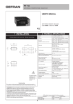
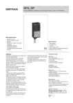
2400
FAST DISPLAY / ALARM UNIT
Main characteristics
• Double configurable input for
strain gauge / potentiometer /
linear signal / TC / RTD
• Two auxiliary analog inputs
• Differential measurement
• High precision: 0.1 % f.s. ±1 digit
• High tripping speed
• Automatic calibration for 6-wire
strain gauge
• Transmitter power supply and
strain gauge probe power supply
• Memory: min. peak, max. peak,
max. peak – min. peak
• 3 configurable alarms, failsafe function
• 2 digital inputs
• up to 4 relay/logic outputs
• 5-digit display
• Serial communication interface:
- RS485/RS232 MODBUS RTU
protocol (optional)
- Profibus DP slave (optional)
• Isolated analog retransmission output
(optional)
Main applications
• Extrusion lines and injection
presses for plastics
• Filling machines
• Food processing plants
• Pressure measurement and trip
points (direct/differential)
• Position measurement and trip
points
• Variable setpoints in fast
processes and automations in
general, with signal
retransmission
PROFILE
Fast microprocessor display / alarm unit,
96 x 48 (1/8 DIN) format.
Built with SMT technology for an extremely complete operator interface with
IP54 protection level (IP65 with protective
cover).
The front panel has a 6-key soft-touch
keyboard and 5-digit LED display of process variable and parameters.
The instrument is appropriate for acquisition of signals with high variation speed.
It has two main analog inputs for many
applications, including differential measurements.
The inputs are configurable from the keyboard and accept standard linear signals
(and custom linearized signals), as well as
signals from pressure probes, load cells,
potentiometers, TC, RTD.
There are two additional analog inputs for
linear signals and two digital inputs for
functions such as alarm latch reset, peak
latch reset, calibration check, hold, alarm
setpoint selection.
The outputs (up to 4) are relay or logic,
and are configurable.
The instrument manages functions such
as storage of maximum peak, minimum
peak, peak-peak values.
An optional, optically isolated analog output is available for retransmission of input
value or peak values.
Alarms
4 (10) completely configurable setpoints.
Selectable “failsafe” function.
MD8 expansion to replace outputs 3 and
4, with 8 additional setpoints.
TECHNICAL DATA
OPERATOR INTERFACE
Display
Configurable from -19999 to 99999 xith
settable decimal point
5 digits bicolors (R/V) 13mm
2 digits (V) 7mm
LED signals: n.14 red
Keys: n.6
Digital communication
The instrument offers an optional RS485
2/4 wire / RS232 serial interface with
MODBUS RTU protocol for access to
instrument parameters, or the option ProfiANALOG INPUTS
bus DP (slave).
Accuracy: 0,1% f.s. ± 1 digit
(0,2% for TC)
Configuration
Min. sampling time:
The programming procedure is facilitated
by the menu structure, with various confi- 2 msec for main inputs
10msec for auxiliary inputs
guration levels for quick and simple data
Resolution:
search.
• without filter: 100000 steps@2msec
• with digital filter (selectable):
100000 steps@20msec
100000 steps@100msec (50Hz)
Custom linearization:
• fixed intervals: 64 sections
• variable intervals: 32 sections max.
• self-learning
INPUT 1, INPUT 2 main inputs
Strain-gauge: 350Ω
Sensitivity 1,5...4mV/V
Jumper power supply: 5/10Vdc 200mA
Potentiometer:
≥100Ω, Ri > 10MΩ @ 2,5Vdc
Linear DC:
±50mV ... ±10V, Ri > 1MΩ
0/4...20mA, Ri = 50Ω
TC - thermocouple:
J 0...1000°C / 32...1832°F
K 0...1300°C / 32...2372°F
R 0...1750°C / 32...3182°F
S 0...1750°C / 32...3182°F
T -200...400°C / -328...752°F
custom -1999...9999
RTD: 2-3 wires
PT100 -200...850°C / -328...1562°F
int./ext. cold junction compensation
INPUT 3 (auxiliary)
Linear DC:
0...10V, 0/4...20mA, Ri = 50Ω
INPUT 4 (auxiliary)
Linear DC:
0...10V, 0/4...20mA, Ri = 50Ω
ALLARMI
Relay: 5A/250Vac cosϕ=1
Logic: 24Vdc source/sink
OUTPUT 1
Relay (NO/NC)* or Logic
(according to model)
OUTPUT 2
Relay (NO/NC)* or Logic
(according to model)
OUTPUT 3**
Relay (NO/NC)* or Logic
(according to model)
OUTPUT 4**
Relay (NO/NC)* or Logic
(according to model)
• The outputs can be assigned to alarm
setpoints directly or via logic functions
(AND, OR).
• The outputs can be delayed or assigned
to a hysteresis value (selectable in engineering units).
• 4 (10) alarm setpoints settable in absolute value, with functions configurable via
keyboard (direct, reverse, deviation, symmetrical deviation).
• Setpoint can be set over the entire
selected scale.
• Minimum or maximum setpoint with
latch.
• Setpoint can be excluded in power-up
phase until the input variable has exceeded the set limit.
A subsequent drop below such limit causes the relay to trip
POWER SUPPLY
100...240Vac/dc ±10%,
20...27Vac/dc ±10%,
50...60Hz; max 20VA
Protection via internal fuse, not replaceable
by operator
PROBE POWER SUPPLY
5/10Vdc - 200mA, 2,5Vdc for potentiometers
TRANSMITTER POWER SUPPLY
24Vdc, ±5% - 100mA
AMBIENT CONDITIONS
Work temperature: 0...50°C
Storage temperature: -20...70°C
Humidity: 20...85% Ur non-condensing
WEIGHT
450g
DIMENSION
ANALOG OUTPUT (optional)
Not available with option of Profibus communication
Isolated 1500V
0/4...20mA, max 500Ω
± 10V, min 500Ω
resolution higher than 0,03%
Configurable via software
COMMUNICATION (optional)
SERIAL INTERFACE:
RS485 2/4 wires optically isolated
Protocol: MODBUS RTU
Profibus DP slave
Protocoll: Profibus DP VO (slave)
96 X 48 X 167 mm
ACCESSORIES
MD8 - EXPANSION UNIT
replaces outputs 3 and 4 with an additional 8 outputs (relay or logic, according to
model)
FRONT COVERS
standard Gefran (see catalog)
WINSTRUM KIT
TTL/RS232 interface wires + CD
CONFIGURATION
* terminal “C” in common
** alternate: version only with OUTPUT3
(switching contact) and interface for MD8
expansion unit
VIA PC:
TTL service interface, connectable to PC
via “Winstrum” kit
CONNECTIONS
Screw connections
• The relay can be energized or de-energized in alarm state (selection via keyboard).
DESCRIPTION FACEPLATE
A - Process variable display, digit height 14mm, red
B - Index value for displayed process variable
C - “FUNCTION” button
D - “LOWER” button
E - “RAISE” button
F - special functions
G - “CAL-RST” button
H - “PEAK” button
I - Alarm setpoint signals, red LEDs
L - Function indicators
IP54 front panel protection (IP65 available)
I
B
A
L
H
G
F
E
D
C
CONNECTION DIAGRAMS
IN1
Model with single main input
Model: 2400 - 0 - X - X - X - X
Strain-gauge
Verde
Bianco
Blu
power supply
90-260Vac / 10-30Vac/dc
max. 15VA; 50/60Hz
Marrone o Arancio
Nero o Giallo
Rosso
Input in current
Input in voltage
Thermocouple
Resistance Thermometer
CAL 1
IN1 Tc, Rtd, Lin, Diff, Pot
+24V transmitter supply
Rtd1
2-wire
connection
probe power supply
(*) PT100 for possible
external cold junction
compensation
3-wire
connection
Potentiometer
4-wire
2-wire
Potentiometer
R ≥ 100Ω
IN2
IN1
Model with double main input
Model: 2400 - 1 - X - X - X - X
Strain-gauge
Strain-gauge
Green
Green
White
White
Black or Yellow
Red
power supply
90-260Vac / 10-30Vac/dc
max. 15VA; 50/60Hz
Black or Yellow
Red
Blue
Brown or Orange
Blue
Brown or Orange
Input in current / voltage
Input in current / voltage
Thermocouple
Thermocouple
(*) PT100 for possible
external cold junction
compensation
(*) PT100 for possible
external cold junction
compensation
+24V transmitter supply
Resistance Thermometer
probe power supply
Resistance Thermometer
* For Profibus
connections,
please refer to
single input model
2-wire
connection
3-wire
connection
2-wire
connection
3-wire
connection
4-wire
2-wire
Potentiometer
Potentiometer
R ≥ 100Ω
!
Apply user’s manual warnings for a correct installation
Potentiometer
R ≥ 100Ω
DIMENSIONS AND CUT OUT
108
115
96
48
70
44,5
92
170
10
Dimensions: 96x48mm (1/8 DIN), depth 167mm
ORDER CODE
POWER SUPPLY
MODEL
2400
0
20...27VAC/DC
1
100...240VAC/DC
0
None
2
RS485
2nd IMAIN INPUT
None
DIGITAL COMMUNICATION
0
Strain-gauge / TC / RTD /
Potentiometer / Linear
1
RETRANSMISION OUTPUT
None
0
Analog 0/4...20mA (0...10V)
(not available in presence of digital
communication “Profibus DP”)
W
3
RS232
P
Profibus DP
(not available in presence of option
“W”)
OUTPUTS
4R
4 relay
4D
4 logic
2R
2 relay + MD8 expansion output
2D
2 logic + MD8 expansion output
Please, contact GEFRAN sales people for the codes availability.
GEFRAN spa reserves the right to make any kind of design or functional modification at any moment without prior notice.
Conformity C/UL/US File no. E216851
The instrument conforms to the European Directives 2004/108/CE and 2006/95/CE with reference to the generic standards:
EN 61000-6-2 (immunity in industrial environment) EN 61000-6-3 (emission in residential environment) EN 61010-1 (safety)
GEFRAN spa via Sebina, 74 - 25050 Provaglio d’Iseo (BS)
Tel. 03098881 - fax 0309839063 - Internet: http://www.gefran.com
DTS_2400_0509_ENG