1
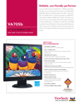
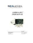
Each click of a dial
opens a doorway to
precision.
2553A
Precision DC Calibrator
Bulletin 2553A-01EN
Yokogawa is a leader in
providing high precision
measurement equipment
electric voltage/current,
electric resistance, pressure,
and temperature fields.
A leadership that dates back
to the early 1970’s.
Features and benefits
High basic accuracy*
DC Voltage: ±75 ppm DC Current: ±120 ppm
Globally respected as the
authority in developing and
producing highly accurate
and precision instruments
and technology, engineers
can trust in first class quality
and reliable performance.
High stability and low noise*
Stability: ±15 ppm/h Noise: 2 μVrms
High resolution
5.5 digits
±120000 count output resolution
*See Page 6 for details.
15
+1 V
5
Variation [ppm]
The new Yokogawa 2553A
is a precision DC calibrator
ideal for calibrating
measurement instruments
including analog meters,
thermometers, temperature
transmitters and data
loggers.
10
0
−5
−10
−15
0
10
20
30
40
50
60
Elapsed time [Minutes]
High stability As reference data.
The 2553A delivers:
Confidence – Yokogawa’s
attention to quality, accuracy
and precision ensures the
engineer can trust in the
product’s reliability.
Familiarity – Ease of use and
intuitive operation are a must
for all engineers and dials for
each digit and 7-segment LEDs
makes the 2553A all the more
simpler to use.
Variety – Flexibility and the
availability of commonly used
thermocouples, RTD generation
and user defined functions
enables an all in one instrument
calibration.
1
2
4
3
5
1 Main set value
4 Output ON/OFF switch
2 Temperature type selection
5 Output terminals
3 Voltage/current range selection
Intuitive operation
Dials and switches are provided for each digit and function. Traditional
7-segment LEDs provide clear visibility.
Various temperature calibrations
The 2553A provides well used K, T, E, J, and additional 6 types of
thermocouples. These 10 types are all regulated in IEC.
It also provides widely used Pt100 as an RTD. Resistance as well as
temperature value can be set as an output value, enabling instrument
calibration by both values.
Use existing 2553 programs*
The 2553A communication command is backwardly compatible with
previous 2553 model. By using 2553 command mode, it is possible to
replace 2553 to 2553A without modifying your programs. It is also possible
to mix 2553As and 2553s in the same system.
TC type
Source Range [˚C]
R
–50 to 1768
S
–50 to 1768
B
0 to 1820
J
–210 to 1200
T
–270 to   400
E
–270 to 1000
K
–270 to 1300
N
–270 to 1300
C
0 to 2315
A
0 to 2500
RTD
Source Range [˚C]
Pt100
–200 to 850
Resistance output
Source Range [Ω]
400 Ω
18 to 400
* Programs may need some modifications.
Comparison with previous model 2553
Range
DC Voltage
DC Current
Temperature
Accuracy (1 V range)
Output resistance
(100 mV range)
Range
Accuracy (1 mA range)
Thermocouple type
RTD
Resistance generation
Main setting digits
Number of dials
Dimensions
Weight
Communication
Interface
2553A
2553
10 mV, 100 mV, 1 V, 10 V, 30 V
10 mV, 100 mV, 1 V, 10 V
±75 ppm (1 year)
±300 ppm (1 year)
≤10 mΩ
≤1.5 Ω
1 mA, 10 mA , 30 mA (MAX. 30 V output), 100 mA
1 mA, 10 mA , 100 mA
±120 ppm (1 year)
±400 ppm (1 year)
R, S, B, J, T, E, K, N, C, A, User defined
R, J, T, E, K
Pt100, User defined
Unsupported
400 Ω range
Unsupported
5.5
4.5
5
3
213 (W) × 132 (H) × 300 (D) mm
228 (W) × 149 (H) × 365 (D) mm
Approx. 3 kg
Approx. 8 kg
USB-TMC, Ethernet,
GP-IB (also 2553 compatible mode) *
GP-IB (option)
Improved items are written in bold.
*Programs may need some modifications.
Application
2553A
Application
Calibrating and testing analog
meters
4
2553A
60.000 mA
The 2553A can calibrate and test analog meters
up to ±32 V voltage and ±120 mA current.
The strong click from the dial enables easy
adjustment of output value without actually
looking at the front panel of 2553A.
Calibrating and testing
temperature controllers
The 2553A can calibrate and test temperature
controllers and data loggers using thermocouple
and RTD.
It provides 10 types thermocouple regulated in
IEC. By setting temperature value, it generates
thermocouple electromotive power and calibrates
temperature controllers. It covers various
temperature controllers, since it generates higher
accuracy voltage than previous model.
2553A supports widely used Pt100. By setting
temperature value, it generates temperature
related resistance value. Settings can be done by
not only temperature but also resistance value,
making it possible to calibrate using resistance
value.
Calibration by temperature value
2553A
120.0˚C
120˚C
2553A
Copper cables
Calibration by resistance value
2553A
320.12 Ω
620˚C
2553A
Internal RJC mode
2553A
60.0˚C
2553A
RJC at output terminals
Since the 2553A has “Internal RJC mode”
which the reference point is output terminals of
2553A, it is possible to connect the objective
measurement instruments by thermocouple
without an external reference junction.
In “External RJC mode”, your choice of Pt100
can be used with versatile terminal for external
sensor.
It also has “Manual RJC mode” which enables
you to set by entering reference value.
mA
2553A
Thermocouple
60˚C
RJC at output
terminals of 2553A
RJC at Input terminals
of controller
External RJC mode
2553A
120.0˚C
RJ sensor
2553A
Calibration by
temperature value
120˚C
Copper cables
User defined temperature
calibration
2553A
The 2553A provides user defined thermocouple
and RTD. By copying text file including relation
parameters between temperature and voltage or
between temperature and resistance, it is able to
generate various types of thermocouple and RTD.
Text files can be easily created by text editor or
Excel on PC. Files can be easily transferred by
drag & drop operations when PC and 2553A is
connected via a USB cable, letting PC recognize
the 2553A’s internal memory as mass storage
drive.
Sample files are available on our Website.
http://tmi.yokogawa.com/products/generators-source/
standard/2553a-precision-dc-calibrator/
Drag & Drop and copy a user
defined file via USB cable
2553A
Voltage and
resistance
5
Temperature
Calibrating and testing sensor
transformers
The 2553A calibrates the transformers and
transmitters for pressure, volume flow, and
temperature. It also calibrates transformers for
analytical instruments such as pH, ORP, EC,
and DO meters. High voltage output accuracy of
2553A will enable support for transformers which
require higher accuracy. 2553A will come in use
even in developing and testing transformers.
2553A
5.0000 V
2553A
Transformer
Simulating the two wire
transmitters
2553A
In 30 mA range, the 2553A can sink the current.
For example, by sinking the current from
the distributors, it can simulate the two wire
transmitters which output 4 to 20 mA signals.
–16.000 mA
4 to 20 mA
2553A
Distributor
Specification
2553A
Specifications
Voltage generation
6
Range
Source range
Resolution
10 mV
100 mV
1V
10 V
30 V
±12.0000 mV
±120.000 mV
±1.20000   V
±12.0000   V
±  32.000   V
100 nV
1 μV
10 μV
100 μV
1 mV
Range
10 mV
100 mV
1V
10 V
30 V
Stability (1h)*
Accuracy (180 days)*
Accuracy (1 year)*
±(ppm of setting + μV)
±(ppm of setting + μV)
±(ppm of setting + μV)
20 +  3
20 +  3
5 + 10
5 + 100
5 + 300
40 +   4
40 +   4
40 + 10
40 + 100
40 + 300
60 +    4
60 +    4
60 +   15
60 + 150
60 + 450
±(% of setting + μV)/˚C
Max. Output
(Typical)
Output
Resistance
10 +   0.1
  5 +   0.3
  3 +   1.5
  3 + 15
  3 + 45
––––
≤10 mA
120 mA
120 mA
  30 mA
Approx. 1 Ω
≤10 mΩ
≤10 mΩ
≤10 mΩ
≤10 mΩ
Temperature Coefficient
Output Noise
0.1 to10 Hz
10 Hz to 10 kHz
1 μVrms
2 μVrms
2 μVrms
15 μVrms
20 μVrms
10 μVrms
10 μVrms
20 μVrms
30 μVrms
50 μVrms
Current generation
Range
1 mA
10 mA
30 mA
100 mA
Range
1 mA
10 mA
30 mA
100 mA
Source range
Resolution
±1.20000 mA
±12.0000 mA
±  32.000 mA
±120.000 mA
10 nA
100 nA
1 μA
1 μA
Stability (1h)*
Accuracy (180 days)*
Accuracy (1 year)*
±(ppm of setting + μA)
±(ppm of setting + μA)
±(ppm of setting + μA)
  5 + 0.015
  5 + 0.15
10 + 0.9
10 + 3
50 + 0.03
70 + 0.4
70 + 1.2
70 + 4
  80 + 0.04
100 + 0.5
100 + 1.5
100 + 5
±(% of setting + μA)/ ˚C
Max. Output
(Typical)
Output
Resistance
  3 + 0.0015
  5 + 0.015
  7 + 0.045
10 + 0.15
15 V
15 V
30 V
15 V
≤100 MΩ
≤100 MΩ
≤ 10 MΩ
≤ 10 MΩ
Temperature Coefficient
Output Noise
0.1 to 10 Hz
10 Hz to 10 kHz
0.015 μArms
0.03  μArms
0.05  μArms
0.3   μArms
0.5 μArms
1  μArms
2  μArms
10  μArms
Temperature generation for RTD
Type
Source Range
Resolution
Accuracy
(180 days)*
Accuracy
(1year)*
Temperature Coefficient
Nominal
Current
Pt100
–200.0 to 850.0˚C
0.1˚C
±0.1˚C
±0.15˚C
±0.006˚C/ ˚C
0.5 to 2 mA
Resistance generation
Range
Source Range
Resolution
400 Ω
18.00 to 400.00 Ω
0.01 Ω
Accuracy (180 days)*
Accuracy (1 year)*
±(ppm of setting + Ω)
±(ppm of setting + Ω)
55 + 0.015
75 + 0.015
Temperature Coefficient
Nominal
Current
±0.002 Ω/ ˚C
0.5 to 2 mA
* 1-hour stability values apply at 23±1˚C. Accuracy values apply at 23±5˚C. Add the temperature coefficient at 5˚C to 18˚C and 28˚C to 40˚C. Accuracy might be
affected by instrument’s inside temperature increase immediately after sinking over 30 mA.
Temperature generation for Thermocouple Setting temperature : Accuracy for 1 year (±˚C)
7
R
  –50˚C: 1.10
    0˚C: 0.80
  100˚C: 0.55
  600˚C: 0.40
1600˚C: 0.40
1768˚C: 0.45
S
  –50˚C: 1.03
    0˚C: 0.75
  100˚C: 0.56
  400˚C: 0.47
1600˚C: 0.44
1768˚C: 0.51
B
  400˚C: 1.00
  600˚C: 0.70
1000˚C: 0.50
1200˚C: 0.44
1820˚C: 0.44
J
–210˚C: 0.25
–100˚C: 0.11
    0˚C: 0.08
1200˚C: 0.15
T
–250˚C: 0.72
–200˚C: 0.29
–100˚C: 0.16
  100˚C: 0.10
  400˚C: 0.09
E
–250˚C: 0.50
–200˚C: 0.20
–100˚C: 0.10
    0˚C: 0.07
1000˚C: 0.12
K
–250˚C: 0.94
–200˚C: 0.30
–100˚C: 0.15
    0˚C: 0.11
  800˚C: 0.15
1300˚C: 0.21
N
–240˚C: 1.00
–200˚C: 0.44
–100˚C: 0.21
    0˚C: 0.16
  800˚C: 0.15
1300˚C: 0.20
C
    0˚C: 0.30
  200˚C: 0.26
  600˚C: 0.25
1000˚C: 0.30
2000˚C: 0.51
2315˚C: 0.70
A
    0˚C: 0.34
  100˚C: 0.29
  600˚C: 0.28
1600˚C: 0.47
2500˚C: 0.79
See page 2 for source range.
Resolution: 0.1˚C
Output Resistance: Approx. 1 Ω
Temperature scale is ITS-90.
Accuracy apply at 23±5˚C and without reference
junction compensation.
Accuracy doesn’t include the thermocouple’s error.
Accuracy for temperature between setting
temperature is calculated by linear interpolation.
Accuracy not shown in left table is ±(60 ppm + 4 µV)
for generated voltage.
3 RJC modes
INT*: Detect temperature of output terminal as
compensation value. Temperature measurement
accuracy is ±0.3˚C.
EXT*: D
etect compensation value by sensor
connected to RJC terminal
MAN: Input compensation value
*When using RJC, add the reference junction
compensation error in “2553A Temperature
generation for Thermocouple (Detail)” on our web site.
Other generation specification
Transient
response time
Voltage/Current generation:
within 500 ms
(No load, Time to reach ±0.01% of final value)
RTD/Resistance generation:
within 0.1 ms
(Time constant at changing current)
Max. LC load
C load 10 μF, L load 1 mH
CMRR
Voltage 120 dB or more (DC, 50/60 Hz)
Current 0.1 uA/V or more (DC, 50/60 Hz)
Rear panel
1
2
3
4
1 RJ sensor connector terminal
3 Ethernet
2 USB interface
4 GP-IB interface
Communication Interface
General specification
Warm-up time
Approx. 30 minutes
Operating environment
Temperature: 5 to 40˚C
Humidity: 20 to 80% RH*
Storage environment
Temperature: –15 to 60˚C
Humidity: 20 to 80% RH
Operating Height
Operating Attitude
Rated power supply voltage
2000 m or less
Horizon
100 to 120 VAC/200 to 240 VAC
Allowable power supply
voltage fluctuation range
90 to 132 VAC/180 to 264 VAC
Rated power supply frequency 50/60 Hz
Allowable power supply
frequency fluctuation range
48 to 63 Hz
Max. power consumption
30 VA
Withstand voltage
Between power and case:
1500 VAC 1 min.
Dimensions
Weight
213 (W) × 132 (H) × 300 (D) mm
Approx. 3 kg
* 20 to 70%RH for 30˚C and over
USB interface (PC connection)
Connector
Type B connector (receptacle)
Electric and mechanical
specifications
Complies with USB Rev. 2.0
supported transfer modes High Speed, Full Speed
Ethernet interface
Connector
RJ-45 connector
Electric and mechanical
specifications
Confirms to the IEEE 802.3
Transfer methods
Transfer speed
100 BASE-TX/10 BASE-T
Max. 100 Mbps
GP-IB interface
Electric and mechanical
specifications
Complies with IEEE St’d 488-1978
Functional specifications
SH1, AH1, T6, L4, SR1, RL1, PP0,
DC1, DT1, C0
Address
0 to 30
Model and Suffix code
Accessories
Model
Model
Suffix code
Description
2553A
Precision DC Calibrator
–VA
Version A
–UC
Deg C
–UF
Deg C and F
–D
UL/CSA standard, PSE
–F
VDE standard
–R
AS standard
–Q
BS standard
–H
GB standard
–N
NBR standard
Product
Specifications
758933
Measurement lead
1 m safety terminal cable with two leads
(red and black), 1 set
758917
Measurement lead
0.75 m safety terminal cable with two leads
(red and black), one set
366961
Measurement lead
1.2 m, Non-isolated 42 V or less
758922
Small alligator clip
adapter
Safety terminal-alligator clip adapter,
1 set containing 2 pieces (red and black)
758921
Fork terminal adapter
Safety terminal-fork terminal adapter,
1 set containing 2 pieces (red and black)
257875
RJ Sensor
For reference junction compensation sensor.
Pt100, 1.95 m
Standard accessories:
Power cord (1), 366961 Measurement lead (1), Rubber feet (1), Terminal plug (1),
User’s manual (1)
Rack Mount
Model
Product
Description
751533-E3
Rack mount kit
EIA standalone installation
751533-J3
Rack mount kit
JIS standalone installation
751534-E3
Rack mount kit
EIA connected installation
751534-J3
Rack mount kit
JIS connected installation
External dimensions
758917 Measurement lead
2 pieces (red and black) 1 set, length: 1.00 m
Used in combination with the 758921 or 758922.
Rating: 1000 V CAT III/19 A
2 pieces (red and black) 1 set, length: 0.75m
Used in combination with the 758921 or 758922.
Rating: 1000 V CAT II/32 A
366961
Measurement lead
758921 Fork terminal adapter
Unit: mm
132
213
20
13
758933 Measurement lead
(24.5)
300
28.5
Non-isolated 42 V or less, 1.2 m
Safety terminal-fork terminal adapter,
1 set containing 2 pieces (red and black)
Related product
AC Voltage Current Standard
2558A
758922
Small alligator clip adapter
Safety terminal (banana female)-to-alligator clip
adapter, 2 pieces (red and black) in 1 set
Rating: 300 V CAT II
Connected to the 758933 or 758917.
High accuracy
AC voltage: ±0.04%
AC current: ±0.05%
257875 RJ Sensor
For reference junction compensation sensor. Pt100.
Temperature measurement accuracy is ±0.3˚C
To avoid electric shocks when using accessories, do not touch the metal parts.
High stability
n
Any company’s names and product names mentioned in this document are trade names,
trademarks or registered trademarks of their respective companies.
AC voltage/current: ±50 ppm/h
Wide generation range
Yokogawa’s Approach to Preserving the Global Environment
AC voltage: 1.00 mV to 1200.0 V
AC current: 1.00 mA to 60.00 A
Wide frequency range
40 to 1000 Hz (Frequency accuracy: ±50 ppm)
model
Description
2558A
AC voltage current standard
• Yokogawa’s electrical products are developed and produced in facilities that have
received ISO14001 approval.
• In order to protect the global environment, Yokogawa’s electrical products are
designed in accordance with Yokogawa’s Environmentally Friendy Product Design
Guidelines and Product Design Assessment Criteria.
This is a Class A instrument based on Emission standards EN61326-1 and EN55011, and is
designed for an industrial environment.
Operation of this equipment in a residential area may cause radio interference, in which case
users will be responsible for any interference which they cause.