1
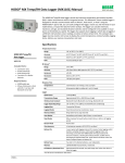
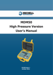
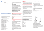
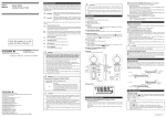
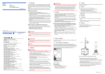
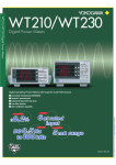
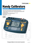
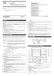
AC Voltage Current Standard
2558A
AC Voltage Current Standard
Simple standalone solution
for calibrating meters, clamps and CTs
Easy Operation
A dial
for each function
High Accuracy
0.04%
0.05%
AC Voltage
AC Current
Wide Output Range
1.00 mV
to 1200.0 V
1.00 mA
to 60.00 A
Bulletin 2558A-01EN
The wide output ranges of 1.00 mV to 1200.0 V* AC and 1.00 mA
to 60.00 A* AC mean that the 2558A is the instrument of choice
for the cost effective calibration of AC analog meters. Rotary
controls and a range of computer interfaces enable the 2558A to
be intuitively operated through the front panel or controlled by an
ATE system.
Frequency / Phase
New AC Voltage Current Standard from “YOKOGAWA”
Main set value
Output divider
Deviation
Output
Functions & Features
Reliable and Simple Operation
Application Case
* With the deviation function, the maximum output is 1440 V and 72 A.
Dials and switches are provided for each digit and function,
and traditional 7-segment LEDs provide clear visibility.
Voltage/
Current range selection
Output ON/OFF switch
Sweep execution switch
Specification
Frequency
range selection
Intuitive operation
Sweep (Voltage/Current/Frequency*)
With a flick of a switch, the output can be swept from 0% to
120% of the main set value with sweep times of 16, 32 or 64
seconds.
* The range of frequency sweep can be set.
Output Divider
Linearity tests can be simply performed by dividing the output
into steps. For example, a setting of 4 will generate steps of
25, 50, 75 and 100% of the set output value.
Direct readout of the deviation
When the deviation dials are adjusted to check the full scale
value on the meter, the deviation from the main output setting is
displayed as a % of full scale.
High accuracy
AC voltage : ±0.04 %
AC current : ±0.05 %
More than sufficient to calibrate meters with class 0.1% accuracy.
10 to 120 % of range
Common current output terminals
The same output terminals are used for all current ranges. Test
times are therefore reduced by avoiding the need to change the
wiring for meters which have different ranges.
2
Wide frequency range
AC voltage : 1.00 mV to 1200.0 V
AC current : 1.00 mA to 60.00 A
40 to 1000 Hz
(Frequency accuracy : ±50 ppm)
6 voltage ranges (100 m/1/10/100/300/1000 ([V])
4 current ranges (100 m/1/10/50 ([A])
The 2558A provides fixed frequencies of 50/60 Hz (commercial)
and 400 Hz (marine and aviation), as well as variable frequencies
from 40 to 1000 Hz.
The high frequency accuracy of the 2558A ( 50 ppm ) also
enables it to be used to calibrate frequency meters.
Multiple 2558As can be synchronized using the internal phase
shifter. This means that two 2558As can be used as accurate
sources of voltage and current for calibrating power meters.
The generation range is 0 to 144 % of range
± (% of setting + % of range)
50/60 Hz
40 ≤ f ≤ 400 Hz
400 < f ≤ 1 kHz
AC voltage
0.03 + 0.01
0.05 + 0.01
0.10 + 0.02
AC current
0.04 + 0.01
0.06 + 0.01
0.12 + 0.02
50/60 Hz
40 ≤ f ≤ 400 Hz
AC voltage
0.013
0.015
0.03
AC current
0.014
0.016
0.032
1 to 10 % of range
Digital display of output
The actual output value is displayed. It is therefore unnecessary
to calculate the output value from the main, divider and deviation
settings.
You can confirm that the output is stable and how it corresponds
to the target meter's reading.
Wide output range
± (% of range)
400 < f ≤ 1 kHz
High stability
AC voltage/current : ±50 ppm/h
± (20 ppm of range + 30 ppm of range)/h
Perform measurements with high repeatability over time
Ex. Set for the output
1. Select the range
2. Main setting : Available for 0 to 120 % of the range
3. Output divider : n & m (n/m of main set value)
m = The number of required calibration points
if the main set value = 100V, m = 5 and n = 1, the output will
be 20 V
4. Deviation : Available for ± 20 % of the main setting
Max. output current is
“72A” at the 50 A range
Main setting
: 60 A
Output divider : n = m
Deviation
: - 20%
2558A
AC Voltage Current Standard
3
AC Voltage Current Standard
WT3000 power analyzer
Power calibration
2558A as the master
Synchronization
(Equipment under test)
Using the output divider and deviation
Calibrating two or more points is quick and simple.
It is only necessary to preselect the number of
required calibration points with the lower divider control
and then use the upper control to step the output to the
next calibration point. The deviation settings will then
enable the output value and error of each calibration
point to be displayed directly.
High
current
2558A as the slave
current
2558
Use existing 2558 programs
The 2558A provides specific functions to enable meters to be calibrated accurately and efficiently.
current
Specification
Condition :
•Accuracy, stability, temperature coefficient
is the sum of the individual units.
•50/60 Hz only.
2558A
The 2558A is backwardly compatible with the previous
2558 model. The new 2558A supports a 2558 command
mode, which means that you can switch from the 2558
to the 2558A without modifying your program. It is also
possible to mix 2558s and new 2558As in the same
system.*
Switching is
O.K.
2558
2558A
Mixing is
O.K.
* Programs may need to be modified due to the
improvement in the response time etc.
Using the output divider
and deviation preset
Comparison with the 2558
n/m
n–1/m
n/m
n+1/m
n–1/m
From a lower value
n+1/m
From a higher value
Using sweep
4
Power meter
2558A as the master
To generate higher current than 72 A, two 2558As
can be connected to double the output to 144 A.
Needle sticking tests can be performed with high
repeatability.
It is possible to stop at any point and sweep around it
in fine detail.
2558A as the slave
current
Higher current output
The deviation preset control can be used to move the output
value in small increments (2 or 5% of the step between
calibration points).
This means that it is possible to finely approach the target
calibration point, either from a lower value or a higher one,
without exceeding it. This is particularly useful when the
friction (hysteresis) of the moving part needs to be taken into
consideration. In this case the point is calibrated twice, once
from a lower value and once more from a higher value and
the final calibration result is the average of the two.
voltage
Application Case
Synchronization
A power calibration system can be created by
using two 2558As (one each for AC voltage and AC
current) together with a Yokogawa WT3000 power
analyzer as the reference.
One of the 2558As acts as the master unit and
provides the synchronizing oscillator signal. The
required power factor is set by adjusting the phase
shifter on the slave unit and monitoring the result on
the WT3000.
A 3 phase power calibrator system can be simply
built by adding further 2558As.
Calibration and test for meters
2558A
Functions & Features
Application
AC Voltage
AC Current
Frequency
SWEEP HOLD
SWEEP UP
SWEEP HOLD
2558A
2558
Output range of
the specified accuracy
1.00 mV to 1200.0 V
1.00 mV to 1200.0 V
Accuracy (50/60 Hz)
± 400 ppm
± 950 ppm
Frequency of
the specified accuracy
40 to 1000 Hz
50 / 60 / 400 Hz
Output range of
the specified accuracy
1.00 mA to 60.00 A
1.00 mA to 60.00 A
Accuracy (50/60 Hz)
± 500 ppm
± 950 ppm
Frequency of
the specified accuracy
40 to 1000 Hz
50 / 60 / 400 Hz
Output range
40 to 1000 Hz
40 to 500 Hz
Accuracy
± 50 ppm
± 1%
Max. output
Approx. 36 VA (60 A/0.6 V)
Approx. 36 VA (60 A/0.6 V)
Stability
± (20 ppm of setting + 30 ppm of range)/h
± (0.03% of range)/h
Dimension (mm)
426 (W) × 132 (H) × 400 (D)
439 (W) × 149 (H) × 415 (D)
5
Specification
1
2
3
4
GP-IB interface
1
(optional, /C1)
5
2Ethernet
3USB interface
(for PC connection)
4Input terminals
for synchronized
operation
Frequency range
SETUP
Accuracy (internal): ± 50 ppm (180 days)
± 100 ppm (1 year)
Mode: Internal / External / FREQUENCY METER
Internal: 50 / 60 / 400 Hz
VAR (40 to 1000 Hz, 0.001 Hz resolution)
External: EXT1 / EXT2
(Use the terminals for the synchronized operation)
FREQUENCY METER: MIN/MAX
Range : 20 to 1000 Hz
Resolution : 0.001 Hz
Sweep, output divider and deviation functions are used
for the frequency.
Specified output range
Resolution
Maximum output
100 mV
0 to 144.00 mV
1 to 120.00 mV
10 uV
—
1V
0 to 1.4400 V
0.01 to 1.2000 V
100 uV
0.5 A or more
10 V
0 to 14.400 V
0.1 to 12.000 V
1 mV
Approx. 3 A
100 V
0 to 144.00 V
1 to 120.00 V
10 mV
Approx. 0.3 A
300 V
0 to 432.0 V
3 to 360.0 V
100 mV
Approx. 0.1 A
1000 V
0 to 1440.0 V
10 to 1200.0 V
100 mV
Approx. 6 mA
100 mA
0 to 144.00 mA
1 to 120.00 mA
10 uA
Approx. 15 V
1A
0 to 1.4400 A
0.01 to 1.2000 A
100 uA
Approx. 15 V
10 A
0 to 14.400 A
0.1 to 12.000 A
1 mA
Approx. 3 V
50 A
0 to 72.00 A
0.5 to 60.00 A
10 mA
Approx. 0.6 V
Condition Frequency
:Internal oscillator
Temperature/Humidity :23 ± 3 °C/20 to 80 %RH
Add the temp. coefficient at 5 to 20°C, 26 to 40°C
Output terminal
Type
Voltage: Plug-in terminal (safety terminal)
Current: Large binding post
Selectable LO terminal to earth or floating.
Max. floating voltage to earth : 12 Vpk
Display
Upper : 180 days
Lower : 1 year
10% to 120% of range
General specifications
Warm-up time: Approx. 30 minutes
Operating environment: Temperature : 5 to 40°C
: Humidity : 20 to 80%RH (no condensation)
: Attitude 2000 m or less
Installation locations: Indoors
Storage environment: Temperature -15 to 60°C
: Humidity 20 to 80%RH (no condensation)
Rated power supply voltage: 100 to 120 VAC / 200 to 240 VAC
Allowable power supply voltage fluctuation range :90 to 132 VAC / 180 to 264VAC
Rated power supply frequency: 50/60 Hz
Allowable power supply frequency fluctuation range : 48 to 63 Hz
Max. power consumption: 200 VA
Weight: Approx. 20 kg
Dimensions: 426(W) x 132(H) x 400(D) mm
1% to 10% of range
± (% of setting + % of range)
Range
Deviation
Target: Voltage / Current / Frequency
Variable range: ±20.00%
Operation: Two dials
Resolution of the first dial : 0.2% of the main setting
Resolution of the second dial : 0.01% of the main setting
Deviation preset: OFF / 0 / 2% / 5%
Main setting: 5 digits LED
Output Divider: 2 digits LED (m and n)
Deviation: 4 digits LED
Output: 5 digits LED
Frequency/Phase: 6 digits LED
Accuracy
GP-IB interface (/C1 optional)
Electrical and mechanical specifications
: Complies with IEEE St’d 488-1978
Functional specifications: SH1, AH1, T6, L4, SR1, RL1, PP0, DC1, DT1, C0
Address: 0 to 30
Specification
Output range
USB PC interface (for PC connection)
Ethernet interface
Output divider
Range
External I/O
Sync. Terminals (two input terminals and two output terminals)
I/O voltage: 3±0.1 Vrms, 2 phase sine wave
Frequency: 40 to 1000 Hz
Input resistance: Approx. 1 MΩ
Output resistance: Approx. 50 Ω
Connector: RJ-45 connector
Electrical and mechanical specifications
:Confirms to the IEEE 802.3
Transmission methods: 100 BASE-TX / 10 BASE-T
Target: Voltage / Current / Frequency
Denominator: m 4 to 15
Numerator: n 0 to 15 (n ≤ m)
Output
Setting: Communication, Beep sound,Sweep speed,
Earth/Floating
Status: Self test, Error log, Product Information
Connector: Type B connector (receptacle)
Electrical and mechanical specifications
: Complies with USB Rev. 2.0
Supported transfer modes: High Speed, Full Speed
Sweep
Target: Voltage / Current / Frequency
Speed: Approx. 16/32/64 sec. selectable
During 0 to 100%, 100 to 0% of setting
Specification
2558A
Application Case
5Output terminals
for synchronized
operation
AC Voltage Current Standard
Functions & Features
Rear Panel
± (% of range)
50/60 Hz
40 Hz ≤ f ≤ 400 Hz
400 Hz < f ≤ 1 kHz
50/60 Hz
40 Hz ≤ f ≤ 400 Hz
400 Hz < f ≤ 1 kHz
0.03 + 0.01
0.04 + 0.01
0.05 + 0.01
0.06 + 0.01
0.10 + 0.02
0.11 + 0.02
0.013
0.014
0.015
0.016
0.030
0.031
100 mV
Accessories
1V
10 V
100 V
300 V
1000 V
100 mA
1A
10 A
0.04 + 0.01
0.055 + 0.01
0.06 + 0.01
0.075 + 0.01
0.12 + 0.02
0.135 + 0.02
0.014
0.0155
0.016
0.0175
50 A
Stability
± (20 ppm of setting + 30 ppm of range)
Condition
Output :1 to 120% of range
Frequency :Internal oscillator
Temperature/Humidity :23±3°C / 20 to 80%RH
Time :1 min. to 1 hour after output ON
Temperature Coefficient (5 to 20ºC, 26 to 40ºC)
50/60 Hz : ±(30 ppm of setting/°C)
Other : ±(50 ppm of setting/°C)
6
0.032
0.0335
758933
Measurement lead set
2 pieces (red and black) in 1 set,
length: 1.00 m Used in combination with the
701959, 758921, 758922, or 758929.
Rating: 1000 V CAT III/19 A
B8506WA
Measurement lead set
2 pieces (red and black) in 1 set,
length : 1.5 m, Rating : 80 A
758917
Measurement lead set
758922
Small Alligator clip adapter set
758929
Large Alligator clip adapter set
2 pieces (red and black) in 1 set,
length: 0.75 m Used in combination with the
701959, 758921, 758922, or 758929.
Rating: 1000 V CAT II/32 A
Safety terminal (banana female)-to-alligator
clip adapter 2 pieces (red and black) in
1 set Rating: 300 V CAT II Connected to the
758933, 758917, or 701901.
Safety terminal (banana female)-to-alligator
clip adapter 2 pieces (red and black) in
1 set Rating: 1000 V CAT II Connected to
the 758933, 758917, or 701901.
758923
Safety terminal adapter set
758931
Safety terminal adapter set
* Wire diameter of cables that can connect to
the adapter
758923 Core wire diameter: 2.5 mm or less,
insulation diameter: 5.0 mm or less
758931 Core wire diameter: 1.8 mm or less,
insulation diameter: 3.9 mm or less
Spring-hold type (banana male) 2 pieces in
1 set. Easy attachment/detachment of the
cable.
*
Screw-fastened type (banana male)
2 pieces in 1 set. Comes with a B9317WD
1.5 mm hexagonal wrench for fixing the
cable in place.
*
Distortion Factor
Voltage output: 0.07% or less
Current output: 0.18% or less
Condition
Output: 40 to 120% of range
Load: Resistance only
20% of the max. output or less
(Current at the voltage output,
or voltage at the current output)
Frequency: 40 to 1000 Hz
758921
Fork terminal adapter set
Two adapters (red and black) to a set. Used
when attaching banana plug to binding post.
701902 / 701903
Safety BNC-BNC cable
701902: Length 1 m, 1000 V CAT II
701903: Length 2 m, 1000 V CAT II
Due to the nature of the product, it is
possible for the user to come in contact
with metal parts and receive electric shock.
Exercise caution when using the product.
7
AC Voltage Current Standard
Model and Suffix Codes
Model
2558A
External dimensions
Suffix code
AC Voltage Current Standard
Option
UL/CSA standard, PSE
-F
VDE standard
-R
AS standard
-Q
BS standard
-H
GB standard
-N
NBR standard
/C1
20
Power code
-D
132
2558A
unit : mm
Description
13
Quantity
Measurement lead set (758933)
1 set (red and black)
Measurement lead set (B8506WA)
1 set (red and black)
Large alligator clip adapter set (758929)
1 set (red and black)
Rubber leg cap
1 set (2)
User’s manual
1 set
High Accuracy
Basic Power Accuracy
±(0.02% of reading + 0.04% of range)
Low Power Factor Error
Rack Mount Kits
Suffix code
Description
751535-E3
Rack mount kit
For EIA
751535-J3
Rack mount kit
For JIS
Part name
Power factor influence when cosø=0
0.03% of S
S is reading value of apparent power
ø is phase angle between voltage and current
Current Range
Optional Accessories
Model
400
Precision Power Analyzer
1
Model
(24.5)
WT3000
Standard Accessories
Power code
13
Related Product
GP-IB interface
Part name
426
Description
Direct Input
0.5/1/2/5/10/20/30 [A] *
or
5m/10m/20m/50m/100m/200m/500m/1/2 [A] *
External Input
50m/100m/200m/500m/1/2/5/10 [V] *
758933
Measurement lead set
1 m, 2 leads in a set
B8506WA
Measurement lead set
1.5 m, 2 leads in a set
758917
Measurement lead set
75 cm, 2 leads in a set
15/30/60/100/150/300/600/1000 [V] *
758922
Alligator clip adapter set
Rating 300 V, 2 adapters in a set
* Voltage range and current range are for crest factor 3
758929
Alligator clip adapter set
Rating 1000 V, 2 adapters in a set
758921
Fork terminal adapter set
Banana-fork adapter, 2 adapters in a set
701902
Safety BNC-BNC cable
1.0 m
701903
Safety BNC-BNC cable
2.0 m
758923
Safety terminal adapter set
Spring-hold type, 2 adapters in a set
758931
Safety terminal adapter set
Screw-fastened type, 2 adapters in a set
Voltage Range
Model
Description
760301
WT3000 1 input element model
760302
WT3000 2 input elements model
760303
WT3000 3 input elements model
760304
WT3000 4 input elements model
Yokogawa's Approach to Preserving the Global Environment
• Yokogawa's electrical products are developed and produced in facilities that have received ISO14001 approval.
• In order to protect the global environment,Yokogawa's electrical products are designed in accordance with Yokogawa's Environmentally Friendly Product
Design Guidelines and Product Design Assessment Criteria.
NOTE
YOKOGAWA METERS & INSTRUMENTS CORPORATION
Global Sales Dept.
YOKOGAWA CORPORATION OF AMERICA
2 Dart Road, Newnan, GA. 30265-1094 U.S.A.
Phone: +1-770-253-7000 Facsimile: +1-770-254-0928
YOKOGAWA EUROPE B. V.
Euroweg 2 3825 HD Amersfoort, THE NETHERLANDS
Phone: +31-88-4641000 Facsimile: +31-88-4641111
YOKOGAWA ENGINEERING ASIA PTE. LTD.
5 Bedok South Road, Singapore 469270 SINGAPORE
Phone: +65-6241-9933 Facsimile: +65-6241-2606
YOKOGAWA AMERICA DO SUL LTDA.
Praca Acapulco, 31-Santo Amaro, Sao Paulo/SP, BRAZIL CEP-04675-190
Phone: +55-11-5681-2400
Facsimile: +55-11-5681-4434
YOKOGAWA ELECTRIC KOREA CO., LTD.
C&M Sales Seoul Office
1301-1305, 13rd floor, Kolon digital tower, 106-1,
Yangpyongdong-5Ga, Yeongdeungpo-Gu, Seoul, 150-105,
Korea
Phone: +82-2-2628-3810 Facsimile: +82-2-2628-3899
Subject to change without notice.
"Before operating the product, read the user’s manual thoroughly for
proper and safe operation."
Tachihi Bld. No.2, 6-1-3 Sakaecho, Tachikawa-shi, Tokyo, 190-8586 Japan
Phone: +81-42-534-1413 Facsimile: +81-42-534-1426
YOKOGAWA AUSTRALIA PTY. LTD.
Tower A/112-118 Talavera Road Macquarie Park, NSW 2113
Australia
Phone: +61-2-8870-1100 Facsimile: +61-2-8870-1111
Represented by:
YOKOGAWA INDIA LTD.
Plot No. 96. Electronic City Complex, Hosur Road, Bangalore 560100, INDIA
Phone: +91-80-4158-6000 Facsimile: +91-80-2852-1442
YOKOGAWA SHANGHAI TRADING CO., LTD.
4F Tower D, Cartelo Crocodile Building, No.568 West Tianshan
Road, Shanghai, CHINA
Phone: +86-21-6239-6363 Facsimile: +86-21-6880-4987
YOKOGAWA MIDDLE EAST B. S. C.(C)
P.O.BOX 10070, Manama, Building 577, Road 2516,
Busaiteen 225, Muharraq, BAHRAIN
Phone: +973-17-358100 Facsimile: +973-17-336100
Sensorik
Messtechnik
A-8010 Graz, Riesstraße 146
Tel.: +43 316 40 28 05, Fax: 40 25 06
Handelsgesellschaft m.b.H.
YOKOGAWA ELECTRIC CIS LTD.
Grokholskiy per. 13, Build. 2, 4th Floor, 129090, Moscow
RUSSIAN FEDERATION
Phone: +7-495-737-7868 Facsimile: +7-495-737-7869
All Rights Reserved, Copyright© 2013, Yokogawa Meters & Instruments Corporation.
[Ed : 01/b]
Printed in Japan, 303(KP)
32