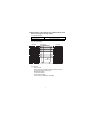
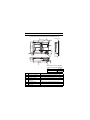
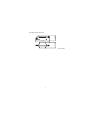
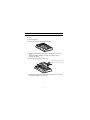
1
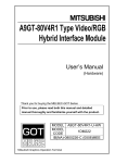
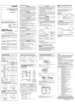
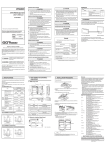
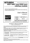
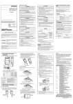
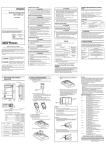
MODEL GT15V-75ROUT
RGB Output Unit
User's Manual
Thank you for purchasing the GOT1000 Series.
Prior to use, please read both this manual and detailed manual
thoroughly to fully understand the product.
MODEL
GT15V-75ROUT-U
MODEL
CODE
1D7M55
IB(NA)-0800349-F(1111)MEE
zSAFETY PRECAUTIONSz
(Always read these precautions before using this equipment.)
Before using this product, please read this manual and the relevant manuals
introduced in this manual carefully and pay full attention to safety to handle the
product correctly.
The precautions given in this manual are concerned with this product.
In this manual, the safety precautions are ranked as "DANGER" and "CAUTION".
DANGER
Indicates that incorrect handling may cause hazardous
conditions, resulting in death or severe injury.
CAUTION
Indicates that incorrect handling may cause hazardous
conditions, resulting in medium or slight personal
injury or physical damage.
Note that the
caution level may lead to a serious accident according to the
circumstances. Always follow the instructions of both levels because they are
important to personal safety.
Please save this manual to make it accessible when required and always forward
it to the end user.
A-1
[DESIGN PRECAUTIONS]
CAUTION
z Do not bunch the control wires or communication cables with the main circuit
or power wires, or lay them close to each other.
As a guide, separate the lines by a distance of at least 100mm (3.94 inches)
otherwise malfunctions may occur due to noise.
[MOUNTING PRECAUTIONS]
DANGER
z Be sure to shut off all phases of the external power supply used by the system
before mounting or removing this unit onto/from the GOT.
Not doing so can cause the unit to fail or malfunction.
CAUTION
z Use this unit in the environment that satisfies the general specifications
described in the User's Manual for the GOT used.
Not doing so can cause an electric shock, fire, malfunction or product damage
or deterioration.
z Tighten the mounting screws within the specified torque range.
Undertightening can cause the GOT to drop, short circuit or malfunction.
Overtightening can cause a drop, short circuit or malfunction due to the
damage of the screws or the GOT.
z Do not touch the conductive and electronic parts of the unit directly.
Doing so can cause a unit malfunction or failure.
A-2
[WIRING PRECAUTIONS]
DANGER
z Be sure to shut off all phases of the external power supply used by the system
before wiring.
Failure to do so may result in an electric shock, product damage or
malfunctions.
CAUTION
z Exercise care to avoid foreign matter such as chips and wire offcuts entering
the GOT. Not doing so can cause a fire, failure or malfunction.
z Make sure to securely connect the cable to the connector of unit.
Incorrect connection may cause malfunctions.
z Do not hold the cable by hand and pull it out from the unit.
When removing the cable from the unit, make sure to hold the connector by
hand and pull it.
Failure to do so may cause malfunctions or damage to the unit or cable.
A-3
[STARTUP/MAINTENANCE PRECAUTIONS]
DANGER
z When power is on, do not touch the terminals.
Doing so can cause an electric shock or malfunction.
z Before starting cleaning, always shut off GOT power externally in all phases.
Not doing so can cause a unit failure or malfunction.
Undertightening can cause a short circuit or malfunction.
Overtightening can cause a short circuit or malfunction due to the damage of
the screws or unit.
CAUTION
z Do not disassemble or modify the unit.
Doing so can cause a failure, malfunction, injury or fire.
z Do not drop the module or subject it to strong shock.
A module damage may result.
z Before touching the unit, always touch grounded metal, etc. to discharge static
electricity from human body, etc.
Not doing so can cause the unit to fail or malfunction.
[DISPOSAL PRECAUTIONS]
CAUTION
z When disposing of the product, handle it as industrial waste.
[TRANSPORTATION PRECAUTIONS]
CAUTION
z Make sure to transport the GOT main unit and/or relevant unit(s) in the
manner they will not be exposed to the impact exceeding the impact
resistance described in the general specifications of the User's Manual for the
GOT used, as they are precision devices.
Failure to do so may cause the unit to fail.
Check if the unit operates correctly after transportation.
A-4
REVISIONS
* The manual number is noted at the lower right of the top cover.
Print Date
*Manual Number
Revision
Mar., 2006
IB(NA)-0800349-A First edition
Feb., 2007
IB(NA)-0800349-B
Partial addition
Chapter 1
Addition
Compliance with the EMC and Low
Voltage Directives
Jul., 2007
IB(NA)-0800349-C
Partial correcitions
Compliance with the EMC and Low
Voltage Directives, Chapter 2, 3, 4
Jun., 2009
IB(NA)-0800349-D
Partial correcitions
Compliance with the EMC and Low
Voltage Directives
Jun., 2011
IB(NA)-0800349-E
Addition
Compliance with the Radio Waves Act
(South Korea)
Nov., 2011
IB(NA)-0800349-F
Partial correcitions
Chapter 2
This manual confers no industrial property rights or any rights of any other kind,
nor does it confer any patent licenses. Mitsubishi Electric Corporation cannot be
held responsible for any problems involving industrial property rights which may
occur as a result of using the contents noted in this manual.
© 2006 MITSUBISHI ELECTRIC CORPORATION
A-5
CONTENTS
1. OVERVIEW .................................................................................................... 1
2. SPECIFICATIONS ......................................................................................... 2
2.1 RGB output unit ....................................................................................... 2
2.2 Specifications of the cables (9-core combined cables) used when
connecting the external display ............................................................... 3
3. PART NAMES AND EXTERNAL DIMENSIONS ........................................... 4
4. INSTALLATION PROCEDURE ..................................................................... 6
A-6
Manuals
The following shows manuals relevant to this product.
Detailed Manual
Manual number
(Model code)
GT15 User's Manual
SH-080528ENG
(Sold separately)
(1D7M23)
GOT1000 Series Connection Manual (Microcomputer,
SH-080871ENG
MODBUS Products, Peripherals) for GT Works3
(1D7MC5)
(Sold separately)
Manual name
Relevant Manuals
For relevant manuals, refer to the PDF manuals stored in the CD-ROM for the
drawing software used.
Packing List
The following items are included.
Model
GT15V-75ROUT
Product
RGB output unit
Mounting screw set (2 screws,2 stickers)
Extend interface relay board
Quantity
1
2
1
Compliance with the EMC and Low Voltage Directives
To configure a system meeting the requirements of the EMC and Low Voltage
Directives when incorporating the Mitsubishi GOT (EMC and Low Voltage
Directives compliant) into other machinery or equipment, refer to "EMC AND
LOW VOLTAGE DIRECTIVES" of the General Description included with the
GOT used.
The CE mark, indicating compliance with the EMC and Low Voltage Directives,
is printed on the rating plate of the GOT.
Compliance with the Radio Waves Act (South Korea)
This product complies with the Radio Waves Act (South Korea).
Note the following when using the product in South Korea.
이 기기는 업무용 (A 급 ) 전자파적합기기로서 판매자 또는 사용자는 이 점을 주의하시기
바라며 , 가정외의 지역에서 사용하는 것을 목적으 로 합니다 .
(The product is for business use (Class A) and meets the electromagnetic
compatibility requirements.
The seller and the user must note the above point, and use the product in a
place except for home.)
A-7
1. OVERVIEW
This User's Manual describes the GT15V-75ROUT RGB output unit (hereinafter
referred to as the RGB output unit).
When mounting RGB output unit with GT1585V-STBA and GT1575V-STBA,
(hereinafter collectively referred to as the GOT), the RGB output unit can external
display screens on GOT.
GOT+GT15V-75ROUT
External display
To use the RGB output unit, make the Communication Settings.
For setting details, refer to GOT1000 Series Connection Manual (Microcomputer,
MODBUS Products, Peripherals) for GT Works3.
For details of system configuration, refer to GOT1000 Series Connection Manual
(Microcomputer, MODBUS Products, Peripherals) for GT Works3.
1
2. SPECIFICATIONS
2.1 RGB output unit
Item
Specifications
RGB output
method (dot's)
Analog RGB(SVGA; 800x600)
Number of
RGB output
channels
1 channel
Dot clock
38.362 MHz
Horizontal
scanning
frequency
37.87 kHz
Vertical
scanning
frequency
60.30 Hz
Horizontal synchronizing timimg
RGB
input
section
Timing chart
RGB
analog
0.7Vp-p
Video signal
20.854 s
RGB
analog
0.7Vp-p
Video signal
15.844ms
VSYNC
HSYNC
Horizontal
sync width
2.190 s
3.206 s Horizontal sync
26.406 s
RGB external
connection
method
Applicable wire
size
Vertical synchronizing timimg
Vertical sync
width
0.156 s
0.106ms
0.607ms
Vertical sync
16.583ms
D-Sub15 pin
9-core combined cable (recommended)
Internal current
consumption (5VDC)
0.11 A
Weight
0.16 kg (0.35 Ib)
2
0.026ms
2.2 Specifications of the cables (9-core combined cables) used
when connecting the external display
(1) Cable specifications
Item
Specifications
Applicable connector
15-pin D-sub for both ends
(2) Connection diagram
GOT side
R
RGND
G
GGND
B
BGND
DGND
HSYNC
VSYNC
DGND
NC
NC
NC
NC
NC
75
1
6
2
7
3
8
10
13
14
5
4
9
11
12
15
coaxical
Twisted pair
CRT side
1
6
2
7
3
8
10
13
14
5
4
9
11
12
15
R
RGND
G
GGND
B
BGND
GND
HSYNC
VSYNC
GND
GND
NC
GND
SDA
SCL
(3) Connector
• GOT connector
Use the connector matching the following model for the GOT.
15-pin D-sub (male) inch screw type
Manufactured by DDK
17HE-R13150-73MC2
• Connector at the display
Use the connector applicable to the display.
3
3. PART NAMES AND EXTERNAL DIMENSIONS
(1) Part names and external dimensions of the RGB output unit
3)
6)
GOT main unit
3
(0.12)
5)
98 (3.86)
7)
8
(0.32)
105 (4.13)
133 (5.24)
6)
2.5
(0.10)
X
8.5
(0.33)
30.5
(1.20)
21.5
(0.85)
1)
113.5
(4.47)
2)
4)
Dimensions of X when the RGB
output unit is mounted to the GOT.
12.1”
18 (0.71)
10.4”
No.
Name
21 (0.83)
Unit: mm (inch)
Description
1)
Connector for RGB output
Connector for connecting a 9-core combined cable
2)
Interface connector
Connector mounted to the GOT
3)
Extension connector
Connector to which a back extension unit is installed
4)
Connector for video/RGB
connection
Connector connecting with the video/RGB interface of
GOT
5)
Board fixing screw
Screw for fixing the extend interface relay board
6)
Mounting screw
Mounting screws for fixing the unit to the GOT
7)
Rating plate
-
4
24 (0.94)
(2) Extend interface relay board
27.5 (1.08)
64 (2.52)
Unit: mm (inch)
5
4. INSTALLATION PROCEDURE
The installation procedure for the RGB output unit is explained using the
GT1575.
(1) Power off the GOT.
(2) Remove two extension unit covers of the GOT.
(3) Attach the extend interface relay board to the extend I/F-2 side on the
GOT.
After the installation, detach the connector cover from the extend
interface relay board.
(4) Fit the RGB output unit in the GOT case.
Remove the connector cover
4)
3)
(5) Fasten the RGB output unit by tightening its mounting screws (4 places)
with tightening torgue 0.36 to 0.48 N•m.
6
(6) Fasten the bus connection unit by tightening the board fixing screws (2
places) with the tightening torque of 0.36 to 0.48 N•m.
5)
6)
(7) When installing an extension unit on the unit that has been installed,
remove the connector cover and the sticker.
When not installing an extension unit on the unit that has been installed,
in order to avoid receiving electrostatic, stick accessory stickers to cover
the top of mounting screws (4 places).
Keep the connector cover fixed.
Keep the sticker stuck as it is.
Connector cover
Accessory sticker
Sticker
Accessory sticker
Point
Remove the screws that fixes the extend interface relay board before
removing the unit.(Above 6))
7
Warranty
Mitsubishi will not be held liable for damage caused by factors found not to be the cause of
Mitsubishi; machine damage or lost profits caused by faults in the Mitsubishi products; damage,
secondary damage, accident compensation caused by special factors unpredictable by
Mitsubishi; damages to products other than Mitsubishi products; and to other duties.
For safe use
• This product has been manufactured as a general-purpose part for general industries, and
has not been designed or manufactured to be incorporated in a device or system used in
purposes related to human life.
• Before using the product for special purposes such as nuclear power, electric power,
aerospace, medicine or passenger movement vehicles, consult with Mitsubishi.
• This product has been manufactured under strict quality control. However, when installing the
product where major accidents or losses could occur if the product fails, install appropriate
backup or failsafe functions in the system.
Country/Region Sales office/Tel
U.S.A
Mitsubishi Electric Automation Inc.
500 Corporate Woods Parkway Vernon
Hills, IL 60061, U.S.A.
Tel : +1-847-478-2100
Brazil
MELCO-TEC Rep. Com.e Assessoria
Tecnica Ltda.
Rua Correia Dias, 184,
Edificio Paraiso Trade Center-8 andar
Paraiso, Sao Paulo, SP Brazil
Tel : +55-11-5908-8331
Germany
Mitsubishi Electric Europe B.V. German
Branch
Gothaer Strasse 8 D-40880 Ratingen,
GERMANY
Tel : +49-2102-486-0
U.K
Mitsubishi Electric Europe B.V. UK
Branch
Travellers Lane, Hatfield, Hertfordshire.,
AL10 8XB, U.K.
Tel : +44-1707-276100
Italy
Mitsubishi Electric Europe B.V. Italian
Branch
Centro Dir. Colleoni, Pal. Perseo-Ingr.2
Via Paracelso 12, I-20041 Agrate Brianza.,
Milano, Italy
Tel : +39-039-60531
Spain
Mitsubishi Electric Europe B.V. Spanish
Branch
Carretera de Rubi 76-80,
E-08190 Sant Cugat del Valles,
Barcelona, Spain
Tel : +34-93-565-3131
France
Mitsubishi Electric Europe B.V. French
Branch
25, Boulevard des Bouvets, F-92741
Nanterre Cedex, France
Tel : +33-1-5568-5568
South Africa
Circuit Breaker Industries Ltd.
Private Bag 2016, ZA-1600 Isando,
South Africa
Tel : +27-11-928-2000
Country/Region Sales office/Tel
Hong Kong
Mitsubishi Electric Automation
(Hong Kong) Ltd.
10th Floor, Manulife Tower, 169 Electric
Road, North Point, Hong Kong
Tel : +852-2887-8870
China
Mitsubishi Electric Automation
(China) Ltd.
4/F Zhi Fu Plazz, No.80 Xin Chang Road,
Shanghai 200003, China
Tel : +86-21-6120-0808
Taiwan
Setsuyo Enterprise Co., Ltd.
6F No.105 Wu-Kung 3rd.Rd, Wu-Ku
Hsiang, Taipei Hsine, Taiwan
Tel : +886-2-2299-2499
Korea
Mitsubishi Electric Automation Korea Co., Ltd.
1480-6, Gayang-dong, Gangseo-ku
Seoul 157-200, Korea
Tel : +82-2-3660-9552
Singapore
Mitsubishi Electric Asia Pte, Ltd.
307 Alexandra Road #05-01/02, Mitsubishi
Electric Building, Singapore 159943
Tel : +65-6470-2460
Thailand
Mitsubishi Electric Automation (Thailand)
Co., Ltd.
Bang-Chan Industrial Estate No.111
Moo 4, Serithai Rd, T.Kannayao,
A.Kannayao, Bangkok 10230 Thailand
Tel : +66-2-517-1326
Indonesia
P.T. Autoteknindo Sumber Makmur
Muara Karang Selatan, Block A/Utara
No.1 Kav. No.11 Kawasan Industri
Pergudangan Jakarta - Utara 14440,
P.O.Box 5045 Jakarta, 11050 Indonesia
Tel : +62-21-6630833
India
Messung Systems Pvt, Ltd.
Electronic Sadan NO:III Unit No15,
M.I.D.C Bhosari, Pune-411026, India
Tel : +91-20-2712-3130
Australia
Mitsubishi Electric Australia Pty. Ltd.
348 Victoria Road, Rydalmere,
N.S.W 2116, Australia
Tel : +61-2-9684-7777
HEAD OFFICE : TOKYO BUILDING, 2-7-3 MARUNOUCHI, CHIYODA-KU, TOKYO 100-8310, JAPAN
NAGOYA WORKS : 1-14, YADA-MINAMI 5-CHOME, HIGASHI-KU, NAGOYA, JAPAN
When exported from Japan, this manual does not require application to the Ministry
of Economy, Trade and Industry for service transaction permission.
Specifications subject to change without notice.
Printed in Japan, November 2011.