1
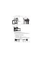
GT15 General Description GT1595-XTBA GT1575V-STBA GT1595-XTBD GT1575V-STBD GT1585V-STBA GT1575-STBA GT1585V-STBD GT1575-STBD GT1585-STBA GT1575-VTBA GT1585-STBD GT1575-VTBD GT1565-VTBA GT1565-VTBD GT1575-VNBA GT1575-VNBD GT1572-VNBA GT1572-VNBD GT1562-VNBA GT1562-VNBD GT1555-VTBD GT1555-QTBD GT1555-QSBD GT1550-QLBD Thank you for purchasing the GOT1000 Series. Prior to use, please read both this manual and detailed manual thoroughly to fully understand the product. MODEL GT15-U(HW) MODEL CODE 1D7M38 IB(NA)-0800322-AB(1312)MEE SAFETY PRECAUTIONS (Always read these precautions before using this equipment.) Before using this product, please read this manual and the relevant manuals introduced in this manual carefully and pay full attention to safety to handle the product correctly. The precautions given in this manual are concerned with this product. In this manual, the safety precautions are ranked as "WARNING" and "CAUTION". WARNING Indicates that incorrect handling may cause hazardous conditions, resulting in death or severe injury. CAUTION Indicates that incorrect handling may cause hazardous conditions, resulting in medium or slight personal injury or physical damage. Note that the caution level may lead to a serious accident according to the circumstances. Always follow the instructions of both levels because they are important to personal safety. Please save this manual to make it accessible when required and always forward it to the end user. [DESIGN PRECAUTIONS] WARNING Some failures of the GOT, communication unit or cable may keep the outputs on or off. Some failures of a touch panel may cause malfunction of the input objects such as a touch switch. An external monitoring circuit should be provided to check for output signals which may lead to a serious accident. Not doing so can cause an accident due to false output or malfunction. If a communication fault (including cable disconnection) occurs during monitoring on the GOT, communication between the GOT and PLC CPU is suspended and the GOT becomes inoperative. For bus connection : The CPU becomes faulty and the GOT becomes inoperative. For other than bus connection : The GOT becomes inoperative. A system where the GOT is used should be configured to perform any significant operation to the system by using the switches of a device other than the GOT on the assumption that a GOT communication fault will occur. Not doing so can cause an accident due to false output or malfunction. Do not use the GOT as the warning device that may cause a serious accident. An independent and redundant hardware or mechanical interlock is required to configure the device that displays and outputs serious warning. Failure to observe this instruction may result in an accident due to incorrect output or malfunction. Incorrect operation of the touch switch(s) may lead to a serious accident if the GOT backlight is gone out. When the GOT backlight goes out, the POWER LED flickers (green/orange) and the display section turns black and causes the monitor screen to appear blank, while the input of the touch switch(s) remains active. This may confuse an operator in thinking that the GOT is in "screensaver" mode, who then tries to release the GOT from this mode by touching the display section, which may cause a touch switch to operate. Note that the following occurs on the GOT when the backlight goes out. • The POWER LED flickers (green/orange) and the monitor screen appears blank The display section of the GT1595-X is an analog-resistive type touch panel. If you touch the display section simultaneously in 2 points or more, the switch that is located around the center of the touched point, if any, may operate. Do not touch the display section in 2 points or more simultaneously. Doing so may cause an accident due to incorrect output or malfunction. When programs or parameters of the controller (such as a PLC) that is monitored by the GOT are changed, be sure to reset the GOT or shut off the power of the GOT at the same time. Not doing so can cause an accident due to false output or malfunction. A-1 [DESIGN PRECAUTIONS] CAUTION Do not bundle the control and communication cables with main-circuit, power or other wiring. Run the above cables separately from such wiring and keep them a minimum of 100mm apart. Not doing so noise can cause a malfunction. Do not press the GOT display section with a pointed material as a pen or driver. Doing so can result in a damage or failure of the display section. When the GOT is connected to the Ethernet network, the available IP address is restricted according to the system configuration. • When multiple GOTs are connected to the Ethernet network : Do not set the IP address (192.168.0.18) for the GOTs and the controllers in the network. • When a single GOT is connected to the Ethernet network : Do not set the IP address (192.168.0.18) for the controllers except the GOT in the network. Doing so can cause the IP address duplication. The duplication can negatively affect the communication of the device with the IP address (192.168.0.18). The operation at the IP address duplication depends on the devices and the system. Turn on the controllers and the network devices to be ready for communication before they communicate with the GOT. Failure to do so can cause a communication error on the GOT. [MOUNTING PRECAUTIONS] WARNING Be sure to shut off all phases of the external power supply used by the system before mounting or removing the GOT main unit to/from the panel. Not doing so can cause the unit to fail or malfunction. Be sure to shut off all phases of the external power supply used by the system before mounting or removing the communication unit, printer unit, option function board or multi-color display board onto/from the GOT. Not doing so can cause the unit to fail or malfunction. When installing the option function board or multi-color display board, wear an earth band etc. to avoid the static electricity. Not doing so can cause a unit corruption. CAUTION Use the GOT in the environment that satisfies the general specifications described in this manual. Not doing so can cause an electric shock, fire, malfunction or product damage or deterioration. When mounting the GOT to the control panel, tighten the mounting screws in the specified torque range (0.36 to 0.48 N•m) with a Phillips-head screwdriver No.2. Undertightening can cause the GOT to drop, short circuit or malfunction. Overtightening can cause a drop, short circuit or malfunction due to the damage of the screws or the GOT. When loading the communication unit or printer unit to the GOT, fit it to the connection interface of the GOT and tighten the mounting screws in the specified torque range (0.36 to 0.48 N•m) with a Phillips-head screwdriver No.2. Under tightening can cause the GOT to drop, short circuit or malfunction. Overtightening can cause a drop, failure or malfunction due to the damage of the screws or unit. When mounting the multi-color display board onto the GOT, tighten the mounting screws within the specified torque range (0.25 to 0.35 N•m) with a Phillips-head screwdriver No.1. Loose tightening may cause the unit and/or GOT to malfunction due to poor contact. Overtightening may damage the screws, unit and/or GOT; they might malfunction. Push the option function board onto the corresponding connector until it clicks, so that it will be secured firmly. Push the multi-color display board onto the corresponding connector so that it will be secured firmly. When inserting a CF card into the GOT, push it into the insertion slot until the CF card eject button will pop out. If not properly inserted, a bad connection may cause a malfunction. A-2 [MOUNTING PRECAUTIONS] CAUTION When inserting/removing a CF card into/from the GOT, turn the CF card access switch off in advance. Failure to do so may corrupt data within the CF card. When removing a CF card from the GOT, make sure to support the CF card by hand, as it may pop out. Failure to do so may cause the CF card to drop from the GOT and break. Operate and store the GOT in environments without direct sunlight, high temperature, dust, humidity, and vibrations. When using the GOT in the environment of oil or chemicals, use the protective cover for oil. Failure to do so may cause failure or malfunction due to the oil or chemical entering into the GOT. [WIRING PRECAUTIONS] WARNING Be sure to shut off all phases of the external power supply used by the system before wiring. Failure to do so may result in an electric shock, product damage or malfunctions. CAUTION Always ground the FG terminal, LG terminal, and Functional ground terminal of the GOT power to the functional ground conductors dedicated to the GOT. Not doing so may cause an electric shock or malfunction. When tightening the terminal screws, use a Phillips-head screwdriver No.2. Terminal screws which are not to be used must be tightened always at torque 0.5 to 0.8 N•m. Otherwise there will be a danger of short circuit against the solderless terminals. Use applicable solderless terminals and tighten them with the specified torque. If any solderless spade terminal is used, it may be disconnected when the terminal screw comes loose, resulting in failure. Correctly wire the GOT power supply section after confirming the rated voltage and terminal arrangement of the product. Not doing so can cause a fire or failure. Tighten the terminal screws of the GOT power supply section in the specified torque range (0.5 to 0.8 N•m). Undertightening can cause a short circuit or malfunction. Overtightening can cause a short circuit or malfunction due to the damage of the screws or the GOT. Exercise care to avoid foreign matter such as chips and wire offcuts entering the GOT. Not doing so can cause a fire, failure or malfunction. The module has an ingress prevention label on its top to prevent foreign matter, such as wire offcuts, from entering the module during wiring. Do not peel this label during wiring. Before starting system operation, be sure to peel this label because of heat dissipation. Plug the communication cable into the connector of the connected unit and tighten the mounting and terminal screws in the specified torque range. Undertightening can cause a short circuit or malfunction. Overtightening can cause a short circuit or malfunction due to the damage of the screws or unit. Plug the QnA/ACPU/Motion controller (A series) bus connection cable by inserting it into the connector of the connected unit until it "clicks". After plugging, check that it has been inserted snugly. Not doing so can cause a malfunction due to a contact fault. A-3 [TEST OPERATION PRECAUTIONS] WARNING Before performing the test operations of the user creation monitor screen (such as turning ON or OFF bit device, changing the word device current value, changing the settings or current values of the timer or counter, and changing the buffer memory current value), read through the manual carefully and make yourself familiar with the operation method. During test operation, never change the data of the devices which are used to perform significant operation for the system. False output or malfunction can cause an accident. [STARTUP/MAINTENANCE PRECAUTIONS] WARNING When power is on, do not touch the terminals. Doing so can cause an electric shock or malfunction. Correctly connect the battery connector. Do not perform the following actions to the battery. • Charging, disassembling, heating, short-circuiting, or soldering the battery, or throwing it into the fire Doing so will cause the battery to produce heat, explode, or ignite, resulting in injury and fire. Before starting cleaning or terminal screw retightening, always switch off the power externally in all phases. Not switching the power off in all phases can cause a unit failure or malfunction. Undertightening can cause a short circuit or malfunction. Overtightening can cause a short circuit or malfunction due to the damage of the screws or unit. CAUTION Do not disassemble or modify the unit. Doing so can cause a failure, malfunction, injury or fire. Do not touch the conductive and electronic parts of the unit directly. Doing so can cause a unit malfunction or failure. The cables connected to the unit must be run in ducts or clamped. Not doing so can cause the unit or cable to be damaged due to the dangling, motion or accidental pulling of the cables or can cause a malfunction due to a cable connection fault. When unplugging the cable connected to the unit, do not hold and pull the cable portion. Doing so can cause the unit or cable to be damaged or can cause a malfunction due to a cable connection fault. Do not drop the module or subject it to strong shock. A module damage may result. Do not drop or give an impact to the battery mounted to the unit. Doing so may damage the battery, causing the battery fluid to leak inside the battery. If the battery is dropped or given an impact, dispose of it without using. Before touching the unit, always touch grounded metals, etc. to discharge static electricity from human body, etc. Not doing so can cause the unit to fail or malfunction. Replace battery with GT15-BAT by Mitsubishi electric Co. only. Use of another battery may present a risk of fire or explosion. Dispose of used battery promptly. Keep away from children. Do not disassemble and do not dispose of in fire. A-4 [TOUCH PANEL PRECAUTIONS] CAUTION For the analog-resistive film type touch panels, normally the adjustment is not required. However, the difference between a touched position and the object position may occur as the period of use elapses. When any difference between a touched position and the object position occurs, execute the touch panel calibration. When any difference between a touched position and the object position occurs, other object may be activated. This may cause an unexpected operation due to incorrect output or malfunction. [BACKLIGHT CHANGING PRECAUTIONS] WARNING Before changing the backlight, always switch off the GOT power externally in all phases (when the GOT is connected to the bus, the PLC CPU power must also be switched off externally in all phases) and remove the GOT from the control panel. Not switching the power off in all phases may cause an electric shock. Not removing the unit from the control panel can cause injury due to a drop. CAUTION When replacing the backlight, use the gloves. Otherwise, it may cause you to be injured. Start changing the backlight more than 5 minutes after switching the GOT power off. Not doing so can cause a burn due to the heat of the backlight. [DISPOSAL PRECAUTIONS] CAUTION When disposing of the product, handle it as industrial waste. When disposing of the battery, dispose of it separately based on the law in each region. (Refer to GT15 User's Manual for details of the battery regulations in the EU member countries.) [TRANSPORTATION PRECAUTIONS] CAUTION When transporting lithium batteries, make sure to treat them based on the transport regulations. (Refer to GT15 User’s Manual for details of the regulated models.) Make sure to transport the GOT main unit and/or relevant unit(s) in the manner they will not be exposed to the impact exceeding the impact resistance described in the general specifications of the GT15 User's Manual, as they are precision devices. Failure to do so may cause the unit to fail. Check if the unit operates correctly after transportation. A-5 REVISIONS Print Date *Manual Number Apr., 2005 IB(NA)-0800322-A Jul., 2005 IB(NA)-0800322-B * The manual number is noted at the lower right of the top cover. Revision First edition Partial corrections Section 2.1, 2.2, 2.3, 3.2, 5.5, 6.1, 6.5, 7.3.4 Partial additions SAFETY PRECAUTIONS, Section 4.3.2, 4.4.2, 5.3, 7.3.2, 7.3.3 Oct., 2005 lB(NA)-0800322-C Partial corrections Chapter 1, Section 2.1 to 2.3 2.2 to 2.4, Section 3.2, 3.3, 3.4, 4.4.1, 5.2, 5.3, 5.5, 7.3.3 Partial additions Product Components, Section 3.4, 4.3.2, 4.3.3, 4.4.1, 7.2 Additions Section 2.1, 3.2.1 to 3.2.4, 3.3.1, 3.3.2 Dec., 2005 lB(NA)-0800322-D Partial corrections Section 4.3.3, 4.4.2 Mar., 2006 lB(NA)-0800322-E Partial corrections Chapter 1, Section 2.1, 2.2, 2.3, 2.4 Partial additions Product Components, Section 3.2, 3.2.1, 3.2.2, 3.2.3, 3.2.4, 3.3, 3.4, 4.3.1, 4.3.2, 4.3.3, 5.2, 5.3, 6.2, 7.3.3 Additions Section 2.5, 3.2.5, 5.3.4 May., 2006 lB(NA)-0800322-F Partial corrections SAFETY PRECAUTIONS, Section 2.3, 2.5 Partial additions Section 3.2.2, 3.2.3, 3.3.2 Aug., 2006 lB(NA)-0800322-G Partial corrections Chapter 6 Partial additions Section 4.3.1, 4.3.3, 4.3.4, 5.3 Sep., 2006 lB(NA)-0800322-H Partial corrections Chapter 4 Oct., 2006 lB(NA)-0800322-I Partial corrections Section 3.2.1, 3.2.2, 3.2.3, 3.2.4, 3.2.5, 3.3.1 Nov., 2006 lB(NA)-0800322-J Partial corrections Section 5.5, 6.4.1, 6.4.2 Feb., 2007 IB(NA)-0800322-K Partial corrections Product Components, Section 3.2, 3.2.1, 3.2.2, 3.2.3, 3.2.4, 3.2.5, 3.3.2, 5.2, 5.3, 6.3, 6.4, 6.4.2, 6.5.1, 6.7.2 Jul., 2007 IB(NA)-0800322-L Partial corrections Section 3.2.2 Oct., 2007 IB(NA)-0800322-M Partial corrections Section 3.2.1 Partial additions Section 3.2.1, 3.2.2, 3.2.3, 3.2.4, 3.2.5 A-6 Print Date *Manual Number Jan., 2008 IB(NA)-0800322-N Feb., 2008 IB(NA)-0800322-O Revision Partial additions SAFETY PRECAUTIONS, Section 3.2, 5.3 Partial corrections Section 5.3 Nov., 2008 IB(NA)-0800322-P Partial corrections Section 7.3.4 Partial additions SAFETY PRECAUTIONS, Section 3.1, 3.2.1, 3.2.2, 3.2.3, 3.2.4, 3.2.5, 7.3.2 Jan., 2009 IB(NA)-0800322-Q Partial corrections Section 5.3 Jun., 2009 IB(NA)-0800322-R Partial additions Chapter 4. Oct., 2009 IB(NA)-0800322-S Partial corrections SAFETY PRECAUTIONS, Manuals Nov., 2009 IB(NA)-0800322-T Partial additions SAFETY PRECAUTIONS, Section 3.2.5, 4.4.3 Feb., 2010 IB(NA)-0800322-U Partial corrections Section 6.4.1 Partial additions Section 4.4.1 Apr., 2010 IB(NA)-0800322-V Partial corrections Section 3.1 Apr., 2011 IB(NA)-0800322-W Partial corrections Chapter 2, Section 3.1, 3.2.1, 3.2.2, 3.2.3, 3.2.4, 3.2.5 Partial additions SAFETY PRECAUTIONS, Section 4.3.1, 4.4.1, 4.4.2, 5.3 Aug., 2011 IB(NA)-0800322-X Partial corrections Compliance with the Radio Waves Act (South Korea) Nov., 2011 IB(NA)-0800322-Y Partial corrections SAFETY PRECAUTIONS, Chapter 1, Section 2.1, 3.1, 3.3, 5.4, 5.5, Chapter 6, 7, Appendix Jan., 2012 IB(NA)-0800322-Z Partial corrections SAFETY PRECAUTIONS, Section 5.3 Apr., 2013 IB(NA)-0800322-AA Partial corrections SAFETY PRECAUTIONS Dec., 2013 IB(NA)-0800322-AB Partial additions Descriptions in French are added for compliance with the cUL standards. Partial corrections Change of the protective ground to the functional ground,Change of the functional ground symbol This manual confers no industrial property rights or any rights of any other kind, nor does it confer any patent licenses. Mitsubishi Electric Corporation cannot be held responsible for any problems involving industrial property rights which may occur as a result of using the contents noted in this manual. © 2005 MITSUBISHI ELECTRIC CORPORATION A-7 CONTENTS 1. FEATURES....................................................................................................................................................... 1 2. PART NAMES................................................................................................................................................... 2 2.1 Part Names and Settings of the GT15 ......................................................................................................2 3. SPECIFICATIONS ............................................................................................................................................ 3 3.1 General Specifications ..............................................................................................................................3 3.2 Power Supply Specifications ....................................................................................................................4 3.2.1 For GOTs powered from the 100 to 240VAC power supply ..........................................................4 3.2.2 For GOTs powered from the 24VDC power supply .......................................................................4 3.3 External Dimensions .................................................................................................................................5 4. EMC AND LOW VOLTAGE DIRECTIVE .......................................................................................................... 6 4.1 Requirements to Meet EMC Directive ......................................................................................................6 4.1.1 EMC directive ................................................................................................................................6 4.1.2 Control panel .................................................................................................................................7 4.1.3 Noise filter (power supply line filter) ...............................................................................................8 4.2 Requirements for Conpliance with the Low Voltage Directive ..................................................................8 4.2.1 Standard subject to GOT ...............................................................................................................8 4.2.2 Power supply .................................................................................................................................8 4.2.3 Control panel .................................................................................................................................9 4.2.4 Grounding ......................................................................................................................................9 4.2.5 External wiring ...............................................................................................................................9 4.3 EMC Directive-Compliant System Configuration ......................................................................................9 4.3.1 Cables .........................................................................................................................................10 4.4 Precautions for Wiring/Connecting the EMC Directive-Compliant Product .............................................10 4.4.1 Power and ground wires wiring method ......................................................................................10 4.4.2 Processing connection cables .....................................................................................................12 4.4.3 Grounding the cable ....................................................................................................................16 5. INSTALLATION .............................................................................................................................................. 17 5.1 Control Panel Inside Dimensions for Mounting GOT ..............................................................................17 5.2 Panel Cutting Dimensions ......................................................................................................................17 5.3 Mounting Position ...................................................................................................................................17 5. INSTALLATION .............................................................................................................................................. 19 5.1 Dimensions intérieures du tableau de commande pour le montage du GOT .........................................19 5.2 Cotes de découpe du panneau ...............................................................................................................19 5.3 Position de montage ...............................................................................................................................19 6. WIRING........................................................................................................................................................... 21 7. MAINTENENCE AND INSPECTION .............................................................................................................. 21 Appendix. CONFIRMING OF VERSIONS AND CONFORMED STANDARDS.................................................. 21 A-8 Manuals The following shows manuals relevant to this product. Detailed Manual Manual Number (Model code) Manual name GT15 User's Manual (Sold separately) SH-080528ENG (1D7M23) Relevant Manual For relevant manuals, refer to the PDF manuals stored in the CD-ROM for the drawing software used. Packing List The GOT product package includes the following: Model name GT1595-X Product Quantity GOT 1 Installation fitting 8 GOT 1 Installation fitting 4 GT1585V-S GT1585-S GT1575V-S GT1575-S GT1575-V GT1575-VN GT1572-VN GT1565-V GT1562-VN GT1555-V GT1555-Q GT1550-Q Compliance with the Radio Waves Act (South Korea) The GOT with the rating plate labeled with the KC mark complies with the Radio Waves Act (South Korea).Note the following when using the product in South Korea. 이 기기는 업무용 (A 급 ) 전자파적합기기로서 판매자 또는 사용자는 이 점을 주의하시기 바라며 , 가정외의 지역에서 사용하는 것을 목적으 로 합니다 . (The product is for business use (Class A) and meets the electromagnetic compatibility requirements. The seller and the user must note the above point, and use the product in a place except for home.) A-9 1. FEATURES (1) (2) (3) Improved monitoring performance and connectivity to FA devices • Using of TFT color liquid crystal display (high intensity, wide angle view and high definition type) provides clear full-color display and displays small characters clearly. (Displays digital images of BMP and other formats in 65536 colors.)*1 • Provides multi-language display function based on Unicode2.1 True Type font and highspeed drawing of beautiful text. • High speed monitoring through high speed communication at maximum of 115.2kbps. • High speed display and high speed touch switch response. More efficient GOT operations including screen design, startup, adjustment, management and maintenance works • 9MB user memory is included as standard. (Memory capacity can be expanded up to 57MB by increasing the option memory)*1 • CF card interface is included as standard. • Font installation is available to increase the system fonts. • Combined use of 4 types of alarms (system alarm, user alarm, alarm history, alarm popup display) realizes more efficient alarm notification. • Maintenance timing report function is available that measures the backlight energization time and notifies of maintenance time. • The USB connector is positioned on the GOT front. This enables the system startup to be performed more efficiently using FA device startup tool, and eliminates the necessity of indirect works (opening and closing the control panel, cable replacement, cable rewiring) in order to improve the working efficiency. • The blown backlight bulb can be confirmed even during screen saving, with the blinked POWER LED at backlight shutoff detection. Enhanced support of FA device setup tools • Transferring and monitoring sequence programs with the personal computer connected to the GOT can be executed when connecting to a PLC CPU with the direct CPU connection or bus connection. (FA transparent function) *1 The specifications differ depending on the GOT to be used. For the specifications, refer to the following. GT15 User’s Manual 1 2. PART NAMES 2.1 Part Names and Settings of the GT15 Example) GT1595 GOT Rear face 7) 13) 17) 8) 16) 15) 2),3) 1) 9) 10) 4) 11) 14) 14) 19) 5) 12) 18) 6) No. Name Description 1) POWER LED Lit in green : Power is correctly supplied , Lit in orange : Screen saving Blinks in orange/green : Blown back light bulb , Not lit : Power is not supplied 2) Display screen Displays the Utility and the user creation screen 3) Touch key For operating touch switches in the Utility and the user creation screen 4) USB interface For connecting a personal computer (Connector type: Mini-B) 5) RS-232 interface For communicating with a controller or connecting a personal computer (Connector type: D sub 9-pin) 6) Power terminal Power input terminal, LG terminal*7, FG terminal 7) Extension interface For installing an extension unit 8) CF card interface For installing a CF card 9) CF card access LED Lit : CF card accessed , Not lit : CF card not accessed 10) CF card access switch Used for accepting or stopping the access to the CF card before removing the CF card from the GOT ON :CF card being accessed (CF card removal prohibited) OFF :CF card not accessed (CF card removal possible) 11) Optional function board interface For installing the optional function board 12) Multi-color display board interface*1*3*8 For installing the multi-color display board Hardware reset switch (Inoperative in the bus connection or with the bus connection unit installed) 13) Reset switch 14) Hole for unit installation fitting Hole for inserting the unit installation fitting 15) Battery holder Houses the battery 16) Human sensor*4 17) Installation switch Sensor that detects human movement *5 Used for OS installations at the GOT startup 18) Video/RGB interface*2 For installing the video input unit, RGB input unit, video/RGB input unit, or RGB output unit 19) Functional ground terminal*6 For earthing *1 For the multi-color display board, refer to the following. GT15 User’s Manual *2 GT1585V-S and GT1575V-S only *3 The GT155 has no multi-color display board. *4 GT1595 and GT1585 only *5 GT1595 only *6 GT155 only *7 The GT155 has no LG terminal. *8 The GT1575-VN, GT1572-VN, and GT1562-VN do not support the 65536-color display even if the multi-color display board is mounted. 2 3. SPECIFICATIONS 3.1 General Specifications Item Operating ambient temperature*1 Température ambiante de fonctionnement *1 Specifications Display section Zone d'affichage 0 to 50°C 0 à 50°C Other than the display section Autre que la zone d'affichage 0 to 55°C 0 à 55°C Storage ambient temperature -20 to 60°C Operating ambient humidity*6 10 to 90% RH, non-condensing Storage ambient humidity*6 10 to 90% RH, non-condensing Frequency Compliant with JIS B3502 and IEC61131-2 Vibration resistance*2 Acceleration Halfamplitude - 3.5mm 5 to 8.4Hz Under intermittent vibration 8.4 to 150Hz Under continuous 5 to 8.4Hz vibration 8.4 to 150Hz 9.8m/s2 - - 1.75mm 4.9m/s2 - No greasy fumes, corrosive gas, flammable gas, excessive conductive dust, and direct sunlight(Same as storage atmosphere) Operating atmosphere Operating altitude*3 2000 m (6562 ft) max. Installation location Inside control panel Overvoltage category *4 II or less *5 2 or less Pollution degree Cooling method Self-cooling Grounding Grounding with a resistance of 100 *2 *3 *4 *5 *6 - Compliant with JIS B3502 and IEC61131-2 (147 m/s2, 3 times each in X, Y and Z directions) Shock resistance *1 Sweep count 10 times each in X, Y and Z directions or less When mounting MELSECNET/H communication unit (GT15-J71LP23-25, GT15-J71BR13) or CC-Link communication unit (GT15-J61BT13), the operating ambient temperature must be reduced 5°C against the maximum values described in general specifications. Lors du montage du module de communication MELSECNET/H (GT15-J71LP23-25, GT15J71BR13) ou du module de communication CC-Link (GT15-J61BT13), la température ambiante de fonctionnement doit être réduite de 5°C par rapport aux valeurs maximales décrites dans les spécifications générales. When using the MELSECNET/10 communication unit (GT15-75J71LP23-Z, GT15-75J71BR13Z) or CC-Link communication unit (GT15-75J61BT13-Z), refer to the manual of the communication unit you use. (Differs with the specification of GOT.) Do not use or store the GOT under pressure higher than the atmospheric pressure of altitude 0m (0ft.). Failure to observe this instruction may cause a malfunction. When an air purge is made inside the control panel by adding pressure, there may be a clearance between the surface sheet and the screen making it difficult to use the touch panel, or the sheet may come off. This indicates the section of the power supply to which the equipment is assumed to be connected between the public electrical power distribution network and the machinery within the premises. Category II applies to equipment for which electrical power is supplied from fixed facilities. The surge voltage withstand level for up to the raged voltage of 300 V is 2500 V. This index indicates the degree to which conductive material is generated in the environment where the equipment is used. In pollution degree 2, only non-conductive pollution occurs but temporary conductivity may be produced due to condensation. For the STN LCD model, the wet-bulb temperature must be 39°C or less. Point Refer to GT15 User's Manual for details of the performance specifications of each GOT. 3 3.2 Power Supply Specifications The following describes the power supply specifications for the GT16. ・3.2.1 For GOTs powered from the 100 to 240VAC power supply ・3.2.2 For GOTs powered from the 24VDC power supply Remark Operation at momentary failure • If an instantaneous power failure occurs in the power supply and continues for more than the permissible period, the GOT will be reset. • Make sure to power on the unit more than 5 seconds after power-off. 3.2.1 For GOTs powered from the 100 to 240VAC power supply Specifications Item GT1575V-STBA, GT1575-STBA, GT1575-VTBA, GT1575-VNBA, GT1572-VNBA, GT1565-VTBA, GT1562-VNBA 100 to 240VAC (+10%, -15%) 50/60Hz±5% 110VA (maximum load) 41W or less 39W or less 28W or less 45A or less (4ms) 40A or less (4ms) (maximum load) (maximum load) GT1585V-STBA, GT1585-STBA GT1595-XTBA Input power supply voltage Input frequency Input max. apparent power Power consumption At backlight off 56W or less 30W or less 50A or less (4ms) (maximum load) Inrush current Allowable momentary power failure time 20ms or less (100VAC or more) Noise immunity Dielectric withstand voltage Insulation resistance Applicable wire size Applicable solderless terminal Applicable tightening torque (Terminal block terminal screw) 1,500Vp-p noise voltage, 1 s noise width (when measuring with a noise simulator under 25 to 60Hz noise frequency) 1500VAC for 1 minute across power terminals and earth 10M or more across power terminals and earth by a 500VDC insulation resistance tester 0.75 to 2 [mm2] Solderless terminal for M3 screw RAV1.25-3, V2-S3.3, V2-N3A, FV2-N3A 0.5 to 0.8 [N•m] 3.2.2 For GOTs powered from the 24VDC power supply Item Input power supply voltage Power consumption At backlight off Inrush current Specifications GT1575V-STBD, GT1575-STBD, GT1585VGT1575-VTBD, GT1595STBD, GT1555GT1555GT1550GT1575-VNBD, GT1555-V XTBD GT1585QTBD QSBD QLBD GT1572-VNBD, STBD GT1565-VTBD, GT1562-VNBD 24VDC (+25%, -20%) 57W or less 43W or less 41W or less 19W or less 18W or less 17W or less 15W or less (2380mA/ (1790mA/ (1710mA/ (790mA/ (750mA/ (710mA/ (620mA/ 24VDC) 24VDC) 24VDC) 24VDC) 24VDC) 24VDC) 24VDC) 32W or less 14W or less 30W or less (1330mA/ (580mA/ 13W or less (540mA/24VDC) (1250mA/24VDC) 24VDC) 24VDC) 100A or 67A or less less (4ms) 115A or less (1ms) (1ms) 60A or less (1ms) (maximum load) (maximum (maximum load) (maximum load) load) Allowable momentary power failure time Noise immunity Dielectric withstand voltage Insulation resistance Applicable wire size Applicable solderless terminal Applicable tightening torque (Terminal block terminal screw) 10 ms or less 500Vp-p noise voltage, 1 s noise width (when measuring with a noise simulator under 25 to 60Hz noise frequency) 500VDC for 1 minute across power terminals and earth 10M or more across power terminals and earth by a 500V DC insulation resistance tester 0.75 to 2 [mm2] Solderess terminal for M3 screw RAV1.25-3, V2-S3.3, V2-N3A, FV2-N3A 0.5 to 0.8 [N•m] 4 3.3 External Dimensions The following shows the external dimensions of each model. GT1595 301(11.85) Unit: mm (inch) 52 (2.05) 5 (0.20) 61 (2.4) 250(9.84) 56 (2.20) 6 (0.24) 382(15.0) Unit : mm(inch) 10 (0.39) 5 (0.20) 320(12.6) 6 (0.24) 242(9.53) 10 (0.39) 316(12.44) 263(10.35) 227(8.94) 296 (11.7) GT157 GT156 190 (7.48) 10 (0.39) 6 (0.24) Unit: mm (inch) 5 (0.20) 152 (5.99) Unit : mm(inch) 60 (2.36) 6 (0.24) 10 (0.39) 135 (5.32) 10 (0.39) 167 (6.58) 110 (4.33) 110 (4.33) 56 (2.20) 10 (0.39) 49 (1.93) 6 (0.24) 288 (11.34) 5 (0.20) 214 (8.43) 5 (0.20) 56 (2.20) 222 (8.74) GT155 120 (4.73) 241 (9.49) 175.5 (6.91) 175 (6.89) 199 (7.83) 10 (0.39) 10 (0.39) 303 (11.93) 252 (9.92) 5 175.5 (6.91) 226 (8.90) 52 (2.05) 10 (0.39) 10 (0.39) 281(11.1) GT1585 397(15.6) 320(12.6) Unit : mm(inch) 4. EMC AND LOW VOLTAGE DIRECTIVE For the products sold in European countries, the conformance to the EMC Directive, which is one of the European Directives, has been a legal obligation since 1996. Also, conformance to the Low Voltage Directive, another European Directives, has been a legal obligation since 1997. Manufacturers who recognize their products must conform to the EMC and Low Voltage Directive are required to declare that their products conform to these Directives and put a "CE mark" on their products. • Authorized representative in Europe Authorized representative in Europe is shown below. Name : Mitsubishi Electric Europe BV Address : Gothaer strase 8, 40880 Ratingen, Germany 4.1 Requirements to Meet EMC Directive EMC Directives are those which require "any strong electromagnetic force is not output to the external.: Emission (electromagnetic interference)" and "It is not influenced by the electromagnetic wave from the external.: Immunity (electromagnetic sensitivity)". Items 4.1.1 thru 4.1.3 summarize the precautions to use GOT and configure the mechanical unit in order to match the EMC directives. Though the data described herein are produced with our best on the basis of the requirement items and standards of the restrictions gathered by Mitsubishi, they do not completely guaranteed that all mechanical unit manufactured according to the data do not always match the above directives. The manufacturer itself which manufactures the mechanical unit must finally judge the method and others to match the EMC directives. The manufacturer itself which manufactures the mechanical unit must finally judge the method and others to match the EMC directives. 4.1.1 EMC directive The standards of the EMC Directive are shown below. Applied standard EN61131-2 : 2007 Test standard Test details Standard value EN55011 Radiated noise*1 Electromagnetic emissions from the product are measured. 30M-230MHz QP: 30dB V/m (30m in measurement range)*2*3 230M-1000MHz QP: 37dB V/m(30m in measurement range)*2*3 EN55011 Conducted noise*1 Electromagnetic emissions from the product to the power line is measured. 150k-500kHz QP:79dB, Mean: 66dB*2 500k-30MHz QP:73dB, Mean: 60dB*2 EN61000-4-2 Electrostatic immunity*1 Immunity test in which static electricity is applied to the cabinet of the equipment. 4kV Contact discharge 8kV Aerial discharge EN61000-4-3 Radiated field AM modulation*1 Immunity test in which field is irradiated to the product. 80-1000MHz:10V/m 1.4-2GHz:3V/m 2.0-2.7GHz:1V/m 80%AM modulation@1kHz EN61000-4-4 Fast transient burst noise*1 Immunity test in which burst noise is applied to the power line and signal lines. Power line:2kV Digital I/O(24V or higher): 1kV (Digital I/O(24V or less))> 250V (Analog I/O, signal lines)> 250V EN61000-4-5 Surge immunity*1 Immunity test in which lightening surge is applied to the product. AC power type Power line (between line and ground) : 2kV Power line (between lines) : 1kV Data communication port : 1kV DC power type Power line (between line and ground) : 0.5kV Power line (between lines) : 0.5kV Data communication port : 1kV EN61000-4-6 Conducted RF immunity*1 Immunity test in which a noise inducted on the power and signal lines is applied. Power line: 10V Data communication port: 10V (continue to next page) 6 Applied standard EN61131-2 : 2007 Test standard Test details Standard value EN61000-4-8 Power supply frequency magnetic field immunity Test for checking normal operations under the circumstance exposed to the ferromagnetic field noise of the power supply frequency (50/60Hz). 30 A/m Test for checking normal operations at instantaneous power failure. AC power type 0.5 cycle 0% (interval 1 to 10s) 250/300 cycle 0% 10/12 cycle 40% 25/30 cycle 70% DC power type 10ms (interval 1 to 10s) EN61000-4-11 Instantaneous power failure and voltage dips immunity *1 *2 *3 The GOT is an open type device (device installed to another device) and must be installed in a conductive control panel. The above test items are conducted in the condition where the GOT is installed on the conductive control panel and combined with the Mitsubishi PLC. QP: Quasi-peak value, Mean : Average value The above test items are conducted in the following conditions. 30M-230MHz QP : 40dB V/m (10m in measurement range) 230M-1000MHz QP : 47dB V/m (10m in measurement range) 4.1.2 Control panel The GOT is an open type device (device installed to another device) and must be installed in a conductive control panel. It not only assure the safety but also has a large effect to shut down the noise generated from GOT, on the control panel. (1) Control panel (a) The control panel must be conductive. (b) When fixing a top or bottom plate of the control panel with bolts, do not coat the plate and bolt surfaces so hat they will come into contact. And connect the door and box using a thick grounding cable in order to ensure the low impedance under high frequency. (c) When using an inner plate to ensure electric conductivity with the control panel, do not coat the fixing bolt area of the inner plate and control panel to ensure conductivity in the largest area as possible. (d) Ground the control panel using a thick grounding cable in order to ensure the low impedance under high frequency. (e) The diameter of cable holes in the control panel must be 10cm (3.94in.). In order to reduce the chance of radio waves leaking out, ensure that the space between the control panel and its door is small as possible. Paste the following EMI gasket directly on the painted surface to seal the space so that the leak of electric wave can be suppressed. Manufacturer Series model name KITAGAWA INDUSTRIES CO., LTD. UC series (Recommended Product) Our test has been carried out on a panel having the damping characteristics of 37dB max. and 30dB mean (measured by 3m method with 30 to 300MHz). (2) Connection of power and ground wires Ground and power supply wires for the GOT must be connected as described below. (a) Provide a grounding point near the GOT. Short-circuit the LG and FG terminals of the GOT (LG: line ground, FG: frame ground) and ground them with the thickest and shortest wire possible (The wire length must be 30cm (11.81in.) or shorter.) The LG and FG terminals function is to pass the noise generated in the PC system to the ground, so an impedance that is as low as possible must be ensured. As the wires are used to relieve the noise, the wire itself carries a large noise content and thus short wiring means that the wire is prevented from acting as an antenna. Note) A long conductor will become a more efficient antenna at high frequency. 7 (b) The earth wire led from the earthing point must be twisted with the power supply wires. By twisting with the earthing wire, noise flowing from the power supply wires can be relieved to the earthing. However, if a filter is installed on the power supply wires, the wires and the earthing wire may not need to be twisted. 4.1.3 Noise filter (power supply line filter) The noise filter (power supply line filter) is a device effective to reduce conducted noise. Except some models, installation of a noise filter onto the power supply lines is not necessary. However conducted noise can be reduced if it is installed. (The noise filter is generally effective for reducing conducted noise in the band of 10MHz or less.) Usage of the following filters is recommended. Model name Manufacturer Rated current Rated voltage FN343-3/01 SCHAFFNER 3A FN660-6/06 SCHAFFNER 6A 250V ZHC2203-11 TDK 3A The precautions required when installing a noise filter are described below. (1) Do not install the input and output cables of the noise filter together to prevent the output side noise will be inducted into the input side cable where noise has been eliminated by the noise filter. Input side Input side (power supply side) (power supply side) Induction Filter Filter Output side (device side) ・Installing the input and output cables together will cause noise induction. Output side (device side) ・Separate the input cable from the output cable. . (2) Connect the noise filter’s ground terminal to the control panel with the shortest cable as possible (approx. 10cm (3.94 in.) or less). 4.2 Requirements for Conpliance with the Low Voltage Directive The Low Voltage Directive requires each device which operates with power supply ranging from 50VAC to 1000V and 75VDC to 1500V to satisfy necessary safety items. In the Sections from 4.2.1 to 4.2.5, cautions on installation and wiring of the GOT to conform to the Low Voltage Directive requires are described. We have put the maximum effort to develop this material based on the requirements and standards of the Directive that we have collected. However, compatibility of the devices which are fabricated according to the contents of this manual to the above Directive is not guaranteed. Each manufacturer who fabricates such device should make the final judgement about the application method of the Low Voltage Directive and the product compatibility. 4.2.1 Standard subject to GOT Standard applied to GOT : EEN61131-2 Programmable controllers - Equipment requirements and tests EN60950-1 Safety of Information Technology Equipment 4.2.2 Power supply The insulation specification of the GOT was designed assuming installation category II. Be sure to use the installation category II power supply to the GOT. The installation category indicates the durability level against surge voltage generated by lightning strike. Category I has the lowest durability; category IV has the highest durability. Category IV Category III Category II Installation Category 8 Category I Category II indicates a power supply whose voltage has been reduced by two or more levels of isolating transformers from the public power distribution. 4.2.3 Control panel Because the GOT is open type equipment (device designed to be stored within another device), be sure to use it only when installed in a control panel. (1) (2) Shock protection In order to prevent those who are unfamiliar with power facility, e.g., an operator, from getting a shock, make sure to take the following measures on the control panel. (a) Store the GOT within the control panel locked, and allow only those who are familiar with power facility to unlock the panel. (b) Build the structure in order that the power supply will be shut off when the control panel is opened. Dustproof and waterproof features The control panel also provides protection from dust, water and other substances. Insufficient ingression protection may lower the insulation withstand voltage, resulting in insulation destruction. The insulation in the GOT is designed to cope with the pollution level 2, so use in an environment with pollustion level 2 or better. Pollution level1 : An environment where the air is dry and conductive dust does not exist. Pollution level2 : An environment where conductive dust does not usually exist, but occasional temporary conductivity occurs due to the accumulated dust. Generally, this is the level for inside the control panel equivalent a control room or on the floor of a typical factory. Pollution level3 : An environment where conductive dust exits and conductivity may be generated due to the accumulated dust. An environment for a typical factory floor. Pollution level4 : Continuous conductivity may occur due to rain, snow, etc. An outdoor environment. 4.2.4 Grounding The following are applicable ground terminals. Use them in the grounded state. Be sure to ground the GOT for ensuring the safety and complying with the EMC Directive. Functional grounding : Improves the noise resistance. 4.2.5 External wiring (1) External devices When a device with a hazardous voltage circuit is externally connected to the GOT, select a model which complies with the Low Voltage Directive's requirements for isolation between the primary and secondary circuits. (2) Insulation requirements Dielectric withstand voltages are shown in the following table. Reinforced Insulation Withstand Voltage (Installation Category II, source : IEC664) Rated voltage of hazardous voltage area Surge withstand voltage (1.2/50 150 VAC or below 2500V 300 VAC or below 4000V s) 4.3 EMC Directive-Compliant System Configuration You can also check the EMC Directive compliance status of the GOT1000 series at the Mitsubishi Electric Factory Automation Global Website. For the latest information, go to the Mitsubishi Electric Factory Automation Global Website. http://www.mitsubishielectric.co.jp/fa/ 9 4.3.1 Cables (1) Cables used (a) For the MELSECNET/H connection (coaxial cable), MELSECNET/10 connection (coaxial cable), and video connection, use double shield coaxial cables. The 5C-2V connector plug is applicable to double-shielded coaxial cable. Connect the 5C-2V connector plug to the coaxial cable inside a double-shielded coaxial cable. Ground the shielded part outside a double-shielded coaxial cable as shown in the following figure. Enlarged view Sheath Sheath Double-shielded coaxial cable of cable Mitsubishi Cable ... 5C-2V-CCY Grounding (b) Internal conducter Insulation material Manufacturer (2) External conductor (Grounding) For the CC-Link IE Field Network connection, use the following cable dedicated to the CCLink IE Field Network. Model name Mitsubishi Electric System & Service Co., Ltd. (c) External conductor SC-E5EW-S M For details of the cables used for conncetions other than the above, refer to the GOT1000 Series Connection Manual. Adjusting a cable for the EMC Directive compliance Modify the cables (including user-produced cable) to ensure compliance with the EMC Directive. For details, refer to Section 4.4.2. 4.4 Precautions for Wiring/Connecting the EMC Directive-Compliant Product Wire and connect GOT1000 series equipments as instructed below. If the GOT1000 series equipments are configured in a way different from the following instructions, the system may not comply with EMC directives. 4.4.1 Power and ground wires wiring method (1) Power and ground wires wiring method Connect the power wire and connection cable as shown in the illustration, and be sure to attach a ferrite core within the range shown below. (Ferrite cores are not required for GT155 .) Select a ferrite core to be attached depending on the usage. (ZCAT3035-1330 manufactured by TDK Corporation or RFC-H13 manufactured by KITAGAWA INDUSTRIES CO.,LTD.) Attach the ferrite core as shown below. Lead the power wire and ground wire as shown in Section 4.1.2 (2). Be sure to ground the LG cable, FG cable, and functional ground cable. 10 (a) 100-240VAC GOT power section GOT power supply section GT1585, GT157 , GT156 , GT1595: Hardware version R (February 2010) or earlier Video/RGB connection INPUT 100-240VAC INPUT 100-240VAC Ferrite core (ZCAT3035-1330) GT1595: Hardware version S (February 2010) or later INPUT 100-240VAC 90mm or less (LG) (FG) Ferrite core (RFC-H13) 11 90mm or less 90mm or less (LG) (FG) (LG) (FG) Ferrite core (ZCAT3035-1330) (b) 24VDC GOT power section GOT power supply section GT1595, GT1585, GT157 , and GT156 GT155 Functional grounding INPUT 24VDC (LG) (FG) 90mm or less (FG) INPUT 24VDC - + Ferrite core (ZCAT3035-1330) * Be sure to ground the functional ground terminal and the FG terminal respectively. When the CC-Link IE controller network communication unit or the CC-Link IE Field Network communication unit is mounted on GT155 Functional grounding INPUT 24VDC -+ 90mm or less (FG) Ferrite core (ZCAT3035-1330) 4.4.2 Processing connection cables Process the cable used with the GOT with the following method. When processing the cable, ferrite core, cable clamp and shielding material are required. The cable clamp used by Mitsubishi Electric for the EMC specification compatibility test is shown below. • TDK corporation brand ZCAT3035-1330 Ferrite Core • Mitsubishi Electric Model AD75CK cable clamp • Japan Zipper Tubing Co., Ltd. Zipper tube SHNJ type (1) BUS connection cable (a) For GT15-QC B, GT15-QC BS • Attach the ferrite core to the cable in the position as illustrated below. • Peel the sheath (with the length shown below) at both ends of the cable, and expose the shield braided wire for grounding. (For grounding with cable clamps. (refer to Section 4.4.3.)) PLC/GOT side Ferrite Core (ZCAT3035-1330) GOT side 60 or less (2.36) 360 or less (14.17) 40 40 360 or less (1.57) (1.57) (14.17) 12 Unit : mm(inch) (b) For GT15-C BS • Cut the connection wire protruding from both ends of the cable to the lengths shown below. • Attach the ferrite core to the cable in the position as illustrated below and insert the ground wire into the ferrite core. • Peel the sheath (with the length shown below) at both ends of the cable, and expose the shield braided wire for grounding. (For grounding with cable clamps. (refer to Section 4.4.3.)) Ferrite Core (ZCAT3035-1330) GOT side PLC/GOT side Ground wires 60 or less 60 or less (280mm (2.36) (2.36) (11.02 inch)) 40 40 360 or less 360 or less (14.17) (14.17) (1.57) (1.57) Unit : mm (inch) (c) For other bus connection cables • Wind cable shield material around the cable, and pull out the grounding braided wire of the cable shield material with the length shown below. • Attach the ferrite core to the cable in the position as illustrated below and insert the braided wire for grounding into the ferrite core. Ferrite Core (ZCAT3035-1330) GOT side 80 (3.15) 40 or less (1.57) (2) 80 (3.15) 40 or less (1.57) Unit : mm (inch) CPU direct connection and computer link connection • (a) (b) (3) Cable shield material Grounding braided wire (200mm (7.87 inch)) Grounding braided wire (50mm (1.97 inch)) PLC side Peel the sheath (with the length shown below) of the cable to expose the shield braided wire for grounding. (For grounding with cable clamps (refer to Section 4.4.3)) For RS-232 GOT side PLC side 230 or less 40 (9.06) (1.57) RS-422 cable (For AC30/100/300R4-25P) GOT side 230 or less 40 (9.06) (1.57) Unit : mm (inch) PLC side Unit : mm (inch) MELSECNET/H connection (PLC to PLC network) and MELSECNET/10 connction (PLC to PLC network) (a) For coaxial cable • Strip the outer insulation layer at both ends of the cable by the length shown below to expose the outer braided shield for grounding. (For grounding with cable clamps (refer to Section 4.4.3.)) • Attach ferrite cores to the cable in the positions as illustrated below. 13 Ferrite Core (ZCAT3035-1330) GOT side 130 or less (5.12) 230 or less (9.06) 40 PLC side 130 or less (5.12) 400 or less (15.75) Unit : mm (inch) 40 (1.57) (1.57) (b) For optical fiber cable • (4) Processing of the cable is not required. CC-Link connection (Intelligent device station) • Strip the outer insulation layer at both ends of the cable by the length shown below to expose the braided shield for grounding. (For grounding with cable clamps (refer to Section 4.4.3.)) • Attach ferrite cores to the cable in the positions as illustrated below. • CC-Link dedicated cable for connecting the GOT and PLC Ferrite Core (ZCAT3035-1330) GOT side 130 (5.12) 230 or less (9.06) PLC side 130 (5.12) 400 or less (1.57) (15.75) 40 40 (1.57) Unit : mm (inch) • CC-Link dedicated cable for connecting the GOT and GOT Ferrite Core (ZCAT3035-1330) GOT side 130 (5.12) 230 or less (9.06) (5) 130 (5.12) 40 230 or less (9.06) (1.57) 40 (1.57) Unit : mm (inch) CC-Link IE Feild Network connection and Ethernet connection • Strip the outer insulation layer at both ends of the cable by the length shown below to expose the braided shield for grounding. (For grounding with cable clamps (refer to Section 4.4.3.)) • Attach ferrite cores to the cable in the positions as illustrated below. Ferrite Core GOT side Controller side (ZCAT3035-1330) 120 or less (4.72) 230 or less 40 (9.06) (1.57) (6) GOT side 40 (1.57) 400 or less (15.75) Unit : mm (inch) External I/O device connection • Strip the outer insulation layer at both ends of the cable by the length shown below to expose the braided shield for grounding. (For grounding with cable clamps (Refer to Section 4.4.3.)) • Connect the braided shield to the connector with the connector cover. • Twist power cables. Braided shield GOT side Connector cover Power cable 360 or less (14.17) External I/O device side 40 40 (1.57) (1.57) 14 360 or less (14.17) Unit : mm (inch) (7) Video/RGB connection (a) Video input • Peel the sheath (with the length shown below) at both ends of the cable, and expose the shield braided wire for grounding. (For grounding with cable clamps. (refer to Section 4.4.3.)) • Attach the ferrite core to the cable in the position as illustrated below. Ferrite Core Camcorder/vision sensor side (ZCAT3035-1330) GOT side 130 or less (5.12) 230 or less (9.06) (b) • • 40 (1.57) (1.57) 130 or less (5.12) 400 or less (15.75) Unit : mm (inch) RGB input/output Wind cable shield material around the cable, and pull out the grounding braided wire of the cable shield material with the length shown below. Attach the ferrite core to the cable in the position as illustrated below. Vision sensor/ personal computer/ Ferrite Core GOT side external display side (ZCAT3035-1330) 40 130 or less or less (1.57) (5.12) (8) 40 Cable shield material Grounding braided wire (50mm) 40 or less (1.57) 130 or less (5.12) Unit : mm (inch) PLC (manufactured by other company), microcomputer, temperature controller, inverter, servo amplifier, CNC, MODBUS(R)/RTU or MODBUS(R)/TCP connection Produce the cable (RS-232 cable, RS-422 / 485 cable) for connecting the GOT to a controller with reference to the GOT1000 Series Connection Manual. POINT Configure the system to meet the EMC Directive specifications for the connected device when connecting the GOT to a controller. The following gives the instructions to ensure the machinery comply with the EMC Directive. However, the manufacturer of the machinery must finally determine how to make it comply with the EMC Directives: if it is actually compliant with the EMC Directives. (a) • • For RS-422 / 485 cable Each signal wire (excluding SG and FG) should be made into a two power wires and connected, then twisted. SDA RDA SDB RDA RDB SDA RDB SDB Make the SG wire more than two wires and connect. • Peel the sheath (with the length shown below) of the created cable to expose the shield braided wire for grounding. (For grounding with cable clamps (refer to Section 4.4.3)) GOT side PLC side 230 or less (9.06) 40 (1.57) Unit : mm (inch) 15 (b) • For RS-232 cable Use a twisted pair style for each signal wire (except SG, FG) with SG. RD SD SD RD DTR DSR DSR DTR SG SG • Peel the sheath (with the length shown below) of the created cable to expose the shield braided wire for grounding. (For grounding with cable clamps (refer to Section 4.4.3)) GOT side PLC side 230 or less (9.06) 40 Unit : mm (inch) (1.57) 4.4.3 Grounding the cable Ground the cable and grounding wire to the control panel where the GOT and base unit are installed. 1) Ground the braided shield portion of the cable to the control panel with the cable clamp (AD75CK). Braided shield Cable clamps For the cable clamp attaching details refer to AD75CK-type Cable Clamping Instruction Manual <IB-68682>. a) For GT15-C EXSS-1 and GT15-C BS Ground the ground wire to the FG terminal of the GOT power supply section. GOT FG terminal Bus connection cable FG wire b) For other bus connection cables Ground the braided wire for grounding to the control panel by tightening a screw. 2) Do not arrange the cable clamp adjacent to other cables which do not clamp. Noise from the control panel may access the GOT from the cable clamp and cause adverse effects. 16 5. INSTALLATION 5.1 Control Panel Inside Dimensions for Mounting GOT Mount the GOT onto the control panel while considering the control panel inside dimensions. Point Applicable cable Some cables may need to be longer than the specified dimensions when connecting to the GOT. Therefore, consider the connector dimensions and bending radius of the cable as well for installation. 5.2 Panel Cutting Dimensions Make holes in the panel according to the dimensions list below. Also, ensure 10mm spaces in upper and lower parts of the panel for mounting fixtures. * Panel thickness : 2 to 4 mm or less B A GOT A [mm] (inch) B [mm] (inch) GT1595 383.5(15.10) (+2(0.08), 0(0)) 282.5(11.12) (+2(0.08), 0(0)) GT1585 302(11.89) (+2(0.08), 0(0)) 228(8.98) (+2(0.08), 0(0)) GT157 289(11.38) (+2(0.08), 0(0)) 200(7.87) (+2(0.08), 0(0)) GT156 227(8.94) (+2(0.08), 0(0)) 176(6.93) (+2(0.08), 0(0)) GT155 153(6.02) (+2(0.08), 0(0)) 121(4.76) (+2(0.08), 0(0)) 5.3 Mounting Position B When mounting the GOT, the following clearances must be left from the other device. Depending on the units and cables connected to the GOT, clearances more than the described dimensions can be required. Therefore, consider the connector dimensions and bending radius of the cable as well for installation. For the lead-in allowance for cables at the bottom of the GOT, refer to the following. GT15 User’s Manual C D E A Panel thickness: 2 to 4mm (0.08 to 0.16inch) According to the dimensions in the following table, leave clearances between the GOT and the other devices. The values enclosed in square brackets apply to the case where no other equipment generating radiated noise (such as a contactor) or heat is installed near the GOT. However, keep the ambient temperature of the GOT to 55°C or lower. Item GT1595 GT1585 GT157 GT156 GT155 GOT only 50(1.97) or more [20(0.79) or more] 50(1.97) or more 50(1.97) or more [20(0.79) or [21(0.83) or 49(1.92) or more more] more] Bus connection unit is fitted 50(1.97) or more [20(0.79) or more] 50(1.97) or more 50(1.97) or more [35(1.38) or [40(1.57) or 50(1.97) or more more] more] A (continue to next page) 17 Item GT1595 GT1585 GT157 GT156 GT155 50(1.97) or more 50(1.97) or more Serial communication unit fitted 50(1.97) or more [20(0.79) or more] [39(1.54) or [21(0.83) or 49(1.92) or more more] more] RS-422 Conversion unit is fitted 50(1.97) or more 50(1.97) or more [20(0.79) or [39(1.54) or 53(2.09) or more 58(2.28) or more more] more] Ethernet communication unit is fitted 50(1.97) or more [20(0.79) or more] MELSECNET/10 communication unit (coaxial) is fitted 50(1.97) or more [20(0.79) or more] CC-Link communication unit (GT15-75J61BT13-Z) fitted A - 50(1.97) or more [20(0.79) or more] - CC-Link communication unit (GT15-J61BT13) fitted 50(1.97) or more [20(0.79) or more] 50(1.97) or more [32(1.26) or more] MELSECNET/10 communication unit (optical) fitted 50(1.97) or more 50(1.97) or more 50(1.97) or more 50(1.97) or more [20(0.79) or [26(1.02) or [43(1.69) or [48(1.89) or more] more] more] more] - MELSECNET/H communication unit (coaxial) fitted 50(1.97) or more 50(1.97) or more 50(1.97) or more [20(0.79) or more] [30(1.18) or [35(1.38) or 64(2.52) or more more] more] MELSECNET/H communication unit (optical) fitted 50 (1.97) or more 50(1.97) or more 50(1.97) or more 50(1.97) or more 79(3.11) or more [23(0.91) or [37(1.46) or [42(1.65) or [20(0.79) or more]*1 more]*1 more]*1 more]*1 CC-Link IE Controller Network Module CC-Link IE Field Network Module 50(1.97) or more [20(0.79) or more] Printer unit fitted 50(1.97) or more 50(1.97) or more [23(0.91) or [28(1.10) or 57(2.24) or more more] more] 50(1.97) or more [29(1.14) or more] 50(1.97) or more [20(0.79) or more] 75(2.95) or more*2 Video input unit fitted - 61(2.40) or more*2 - - RGB input unit fitted - 50(1.97) or more [20(0.79) or more]*3 - - Video/RGB input unit fitted - 61(2.40) or more*2*3 75(2.95) or more*2*3 - - RGB output unit fitted - 50(1.97) or more [20(0.79) or more]*3 - - CF card unit 50(1.97) or more [20(0.79) or more] CF card extension unit 50(1.97) or more 50(1.97) or more [20(0.79) or [49(1.93) or 63(2.48) or more 68(2.48) or more 97(3.82) or more more] more] Output/Input unit 50(1.97) or more [20(0.79) or more] 50(1.97) or more 50(1.97) or more [24(0.94) or [29(1.14) or 58(2.28) or more more] more] Sound Interface Unit 50(1.97) or more [20(0.79) or more] (When the CF card is not used) 50(1.97) or more [20(0.79) or more] B C - 80(3.15) or more [20(0.79) or more] (When the CF card is used) D 50(1.97) or more [20(0.79) or more] 100(3.94) or more 50(1.97) or more [20(0.79) or more] E 100(3.94) or more [20(0.79) or more] Unit: mm (inch) *1 This value differs depending on the cable used. Please contact your local Mitsubishi Electric System & Service Co.,Ltd. The value indicated in the table is a reference value. *2 This value is for use of the coaxial cable 3C-2V (JIS C 3501). For specifications of the cable, refer to the following manual. 18 *3 MODEL GT15V-75V4R1 Video/RGB Input Unit MODEL GT15V-75V4 Video Input Unit MODEL GT15V-75R1 RGB Input Unit User's Manual (Section 2.4.1 Specifications of the cables (coaxial cables) used when displaying video images) This value differs depending on the cable used. If the bending radius of the cable used is greater than the value specified above, apply the value of the cable used. POINT Refer to GT15 User's Manual for details of the Control Panel Inside Temperature and Mounting Angle, Installation Procedure of each GOT. 5. INSTALLATION 5.1 Dimensions intérieures du tableau de commande pour le montage du GOT Montez le GOT sur le tableau de commande en tenant compte des dimensions intérieures du tableau de commande. Point Câble applicable Certains câbles peuvent être plus longs que les dimensions spécifiées lors de la connexion au GOT. Par conséquent, prenez également en compte les dimensions du connecteur et le rayon de courbure du câble pour l'installation. 5.2 Cotes de découpe du panneau B Faites des trous dans le panneau en suivant les dimensions ci-dessous. Veillez à laisser des espaces de 10mm dans les parties supérieure et inférieure du panneau pour les fixations. * Épaisseur du panneau : 2 à 4mm ou moins A GOT A [mm] (pouce) B [mm] (pouce) GT1595 383,5(15,10) (+2(0,08), 0(0)) 282,5(11,12) (+2(0,08), 0(0)) GT1585 302(11,89) (+2(0,08), 0(0)) 228(8,98) (+2(0,08), 0(0)) GT157 289(11,38) (+2(0,08), 0(0)) 200(7,87) (+2(0,08), 0(0)) GT156 227(8,94) (+2(0,08), 0(0)) 176(6,93) (+2(0,08), 0(0)) GT155 153(6,02) (+2(0,08), 0(0)) 121(4,76) (+2(0,08), 0(0)) 5.3 Position de montage B Lors du montage du GOT, laissez les espaces suivants pour les autres dispositifs. En fonction des modules et des câbles connectés au GOT, il peut être nécessaire de laisser des espaces plus importants que les dimensions indiquées. Par conséquent, prenez également en compte les dimensions du connecteur et le rayon de courbure du câble pour l'installation. Pour connaître l'espace à laisser pour les câbles sous le GOT, référez-vous à ce qui suit. GT15 User’s Manual D C E A Épaisseur du panneau : 2 à 4mm (0,08 à 0,16 pouce) 19 Laissez les espaces entre le GOT et les autres dispositifs en fonction des dimensions contenues dans le tableau suivant. Les valeurs entre parenthèses s'appliquent au cas où aucun dispositif générant des émissions sonores (comme un contacteur) ou de la chaleur n'est installé près du GOT. Toutefois, maintenez la température ambiante du GOT à 55°C ou moins. Article GT1595 GT1585 Unité de connexion de bus encastrée 50 (1,97) ou plus [20 (0,79) ou plus] GT155 50 (1,97) ou plus 50 (1,97) ou plus 49 (1,92) ou plus [39 (1,54) ou plus] [21 (0,83) ou plus] 50 (1,97) ou plus [20 (0,79) ou plus] 50 (1,97) ou plus [39 (1,54) ou plus] Module de communication Ethernet encastré 53 (2,09) ou plus 58 (2,28) ou plus - 50 (1,97) ou plus [20 (0,79) ou plus] Module de communication MELSECNET/10 (coaxial) encastré 50 (1,97) ou plus [20 (0,79) ou plus] Module de communication CC-Link (GT15-75J61BT13-Z) encastré 50 (1,97) ou plus [20 (0,79) ou plus] - 50 (1,97) ou plus [20 (0,79) ou plus] 50 (1,97) ou plus [32 (1,26) ou plus] Module de communication CC-Link (GT15-J61BT13) encastré Module de communication MELSECNET/10 (optique) encastré Module de communication MELSECNET/H (coaxial) encastré A Module de communication MELSECNET/H (optique) encastré Module réseau de contrôleur CC-Link IE Module réseau de champ CC-Link IE 50 (1,97) ou plus [20 (0,79) ou plus] - Module d'entrée vidéo/RGB encastré - Module de sortie/entrée 50 (1,97) ou plus 50 (1,97) ou plus 57 (2,24) ou plus [23 (0,91) ou plus] [28 (1,10) ou plus] - 61 (2,40) ou plus*2 75 (2,95) ou plus*2 50 (1,97) ou plus [20 (0,79) ou plus]3 61 (2,40) ou plus*2*3 75 (2,95) ou plus*2*3 50 (1,97) ou plus [20 (0,79) ou plus]*3 Module de carte CF Module d'extension de carte CF 50 (1,97) ou plus 50 (1,97) ou plus 79 (3,11) ou plus [37 (1,46) ou [42 (1,65) ou plus]*1 plus]*1 50 (1,97) ou plus [29 (1,14) ou plus] 50 (1,97) ou plus [20 (0,79) ou plus] Module d'entrée RGB encastré - 50 (1,97) ou plus 50 (1,97) ou plus 64 (2,52) ou plus [30 (1,18) ou plus] [35 (1,38) ou plus] 50 (1,97) ou plus [23 (0,91) ou plus]*1 50 (1,97) ou plus [20 (0,79) ou plus] Module d'entrée vidéo encastré Module de sortie RGB encastré - 50 (1,97) ou plus 50 (1,97) ou plus 50 (1,97) ou plus [26 (1,02) [43 (1,69) ou plus] [48 (1,89) ou plus] ou plus] 50 (1,97) ou plus [20 (0,79) ou plus] 50 (1,97) ou plus [20 (0,79) ou plus]*1 Imprimante encastrée - - - - - - - - 50 (1,97) ou plus [20 (0,79) ou plus] 50 (1,97) ou plus [20 (0,79) ou plus] 50 (1,97) ou plus [49 (1,93) ou plus] 50 (1,97) ou plus [20 (0,79) ou plus] 63 (2,48) ou plus 68 (2,48) ou plus 97 (3,82) ou plus 50 (1,97) ou plus 50 (1,97) ou plus 58 (2,28) ou plus [24 (0,94) ou plus] [29 (1,14) ou plus] Module d'interface acoustique 50 (1,97) ou plus [20 (0,79) ou plus] (Quand la carte CF n'est pas utilisée) 50 (1,97) ou plus [20 (0,79) ou plus] B C GT156 50 (1,97) ou plus 50 (1,97) ou plus 50 (1,97) ou plus [35 (1,38) ou plus] [40 (1,57) ou plus] Module de communication série encastré Unité de conversion RS-422 encastrée GT157 50 (1,97) ou plus 50 (1,97) ou plus 49 (1,92) ou plus [20 (0,79) ou plus] [21 (0,83) ou plus] GOT uniquement 80 (3,15) ou plus [20 (0,79) ou plus] (Quand la carte CF est utilisée) 50 (1,97) ou plus [20 (0,79) ou plus] D 50 (1,97) ou plus [20 (0,79) ou plus] E 100 (3,94) ou plus [20 (0,79) ou plus] 100 (3,94) ou plus Unité : mm (pouce) 20 *1 Cette valeur diffère selon le câble utilisé. Contactez le bureau local Mitsubishi Electric System & Service Co.,Ltd. La valeur indiquée dans le tableau est une référence. *2 Cette valeur est utilisée pour le câble coaxial 3C-2V (JIS C 3501). Pour connaître les spécifications du câble, référez-vous au manuel suivant. MODEL GT15V-75V4R1 Video/RGB Input Unit MODEL GT15V-75V4 Video Input Unit MODEL GT15V-75R1 RGB Input Unit User's Manual (Section 2.4.1 Spécifications des câbles (câbles coaxiaux) utilisés lors de l'affichage d'images vidéo) *3 Cette valeur diffère selon le câble utilisé. Si le rayon de courbure du câble utilisé est supérieur à la valeur spécifiée ci-dessus, appliquez la valeur du câble utilisé. POINT Référez-vous au Manuel d'utilisation du GT15 pour obtenir des détails sur la température intérieure et l'angle de montage du tableau de commande et sur la procédure d'installation de chaque GOT. 6. WIRING For the wiring, refer to the following. GT15 User’s Manual 7. MAINTENENCE AND INSPECTION For the maintenance and inspection, refer to the following. GT15 User’s Manual APPENDIX. CONFIRMING OF VERSIONS AND CONFORMED STANDARDS For the confirming of versions and conformed standards, refer to the following. GT15 User’s Manual 21 Warranty Mitsubishi will not be held liable for damage caused by factors found not to be the cause of Mitsubishi; machine damage or lost profits caused by faults in the Mitsubishi products; damage, secondary damage, accident compensation caused by special factors unpredictable by Mitsubishi; damages to products other than Mitsubishi products; and to other duties. For safe use • This product has been manufactured as a general-purpose part for general industries, and has not been designed or manufactured to be incorporated in a device or system used in purposes related to human life. • Before using the product for special purposes such as nuclear power, electric power, aerospace, medicine or passenger movement vehicles, consult with Mitsubishi. • This product has been manufactured under strict quality control. However, when installing the product where major accidents or losses could occur if the product fails, install appropriate backup or failsafe functions in the system. Country/Region Sales office/Tel U.S.A Mitsubishi Electric Automation Inc. 500 Corporate Woods Parkway Vernon Hills, IL 60061, U.S.A. Tel : +1-847-478-2100 Brazil MELCO-TEC Rep. Com.e Assessoria Tecnica Ltda. Rua Correia Dias, 184, Edificio Paraiso Trade Center-8 andar Paraiso, Sao Paulo, SP Brazil Tel : +55-11-5908-8331 Germany Mitsubishi Electric Europe B.V. German Branch Gothaer Strasse 8 D-40880 Ratingen, GERMANY Tel : +49-2102-486-0 U.K Mitsubishi Electric Europe B.V. UK Branch Travellers Lane, Hatfield, Hertfordshire., AL10 8XB, U.K. Tel : +44-1707-276100 Italy Mitsubishi Electric Europe B.V. Italian Branch Centro Dir. Colleoni, Pal. Perseo-Ingr.2 Via Paracelso 12, I-20041 Agrate Brianza., Milano, Italy Tel : +39-039-60531 Spain Mitsubishi Electric Europe B.V. Spanish Branch Carretera de Rubi 76-80, E-08190 Sant Cugat del Valles, Barcelona, Spain Tel : +34-93-565-3131 France Mitsubishi Electric Europe B.V. French Branch 25, Boulevard des Bouvets, F-92741 Nanterre Cedex, France Tel : +33-1-5568-5568 South Africa Circuit Breaker Industries Ltd. Private Bag 2016, ZA-1600 Isando, South Africa Tel : +27-11-928-2000 Country/Region Sales office/Tel Hong Kong Mitsubishi Electric Automation (Hong Kong) Ltd. 10th Floor, Manulife Tower, 169 Electric Road, North Point, Hong Kong Tel : +852-2887-8870 China Mitsubishi Electric Automation (China) Ltd. 4/F Zhi Fu Plazz, No.80 Xin Chang Road, Shanghai 200003, China Tel : +86-21-6120-0808 Taiwan Setsuyo Enterprise Co., Ltd. 6F No.105 Wu-Kung 3rd.Rd, Wu-Ku Hsiang, Taipei Hsine, Taiwan Tel : +886-2-2299-2499 Korea Mitsubishi Electric Automation Korea Co., Ltd. 1480-6, Gayang-dong, Gangseo-ku Seoul 157-200, Korea Tel : +82-2-3660-9552 Singapore Mitsubishi Electric Asia Pte, Ltd. 307 Alexandra Road #05-01/02, Mitsubishi Electric Building, Singapore 159943 Tel : +65-6470-2460 Thailand Mitsubishi Electric Automation (Thailand) Co., Ltd. Bang-Chan Industrial Estate No.111 Moo 4, Serithai Rd, T.Kannayao, A.Kannayao, Bangkok 10230 Thailand Tel : +66-2-517-1326 Indonesia P.T. Autoteknindo Sumber Makmur Muara Karang Selatan, Block A/Utara No.1 Kav. No.11 Kawasan Industri Pergudangan Jakarta - Utara 14440, P.O.Box 5045 Jakarta, 11050 Indonesia Tel : +62-21-6630833 India Messung Systems Pvt, Ltd. Electronic Sadan NO:III Unit No15, M.I.D.C Bhosari, Pune-411026, India Tel : +91-20-2712-3130 Australia Mitsubishi Electric Australia Pty. Ltd. 348 Victoria Road, Rydalmere, N.S.W 2116, Australia Tel : +61-2-9684-7777 HEAD OFFICE : TOKYO BUILDING, 2-7-3 MARUNOUCHI, CHIYODA-KU, TOKYO 100-8310, JAPAN NAGOYA WORKS : 1-14, YADA-MINAMI 5-CHOME, HIGASHI-KU, NAGOYA, JAPAN When exported from Japan, this manual does not require application to the Ministry of Economy, Trade and Industry for service transaction permission. Specifications subject to change without notice. Printed in Japan, December 2013.