1
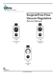
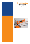
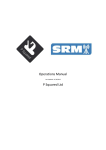
*smith&nephew
VERSAJET™ II
Hydrosurgery System
EN
*smith&nephew
VERSAJET™ II
User guide
Hydrosurgery System
Table of contents
page number
Indications4
Troubleshooting guide
14
Safety4
Glossary of symbols
16
Precautions4
Technical information
16
System components
System specifications
17
Console6
Console front panel
17
Front panel layout
Console rear panel
17
Footswitch7
Product dimensions and weights
17
Back panel layout
8
Handpiece components
8
Single-use handpiece
environmental conditions
17
Single-use handpiece asssebly
8
Console environmental conditions
17
Handpiece options
9
Electromagnetic compatibility
18
System set-up
10
Console set-up
10
Connecting the footswitch
10
Appendix A
Power cord socket
10
Turning the console ON
10
Handpiece quick set-up pictorial guide
11
Company position regarding
the reprocessing and reuse of
single-use only medical devices
Single-use handpiece
set-up and system priming
12
Warnings4
6
6
Console maintenance and
cleaning13
Maintenance13
Cleaning13
Disposal of the console
and accessories
13
Warranty20
Appendix B
20
21
Ordering information
Appendix C
22
Console performance and safety check
Global Customer Service
263
EN
Indications
any sharp instrument, care and attention must
be maintained while using the VERSAJET II Plus
handpieces near delicate vessels and structures.
The VERSAJET II Hydrosurgery System is intended
for wound debridement (acute, chronic wounds and
burns), soft tissue debridement and cleansing of the
surgical site in applications that, in the physician's
judgment, require sharp debridement and pulsed
lavage irrigation.
• VERSAJET II is intended primarily for use in the
operating room environment. Only the 45 degree
VERSAJET II Exact handpieces (66800041 and
66800042) are suitable for use outside the
operating room. Attention to universal infection
control procedures should be applied when using
the device outside the controlled environment of
the operating room.
Safety
The VERSAJET II system is designed for use by
qualified and trained medical professionals. It is
recommended to study this user guide, paying
particular attention to all Warnings and Precautions,
prior to any surgical procedure. Improper system
use or set up, or failure to follow this user guide
may cause injury or damage not covered under the
warranty.
• The 15 degree, 14mm VERSAJET II Exact handpiece
(66800040) and all of the VERSAJET II Plus
handpieces (66800043, 66800044 and 66800045)
should not be used outside the operating room due
to the potential of excessive misting or spraying.
• If the VERSAJET II Exact 45 degree handpieces are
used outside the operating room, ensure the floor
immediately surrounding the treatment area is
covered and any splashes cleaned after treatment
is complete.
Warnings
• This device should be used with particular care
in patients with hemophilia or other blood clotting
disorders and in patients receiving anti-coagulant
medication.
Precautions
• Always begin debridement procedures at the
lowest power setting and increase as necessary
to the optimal setting for the type of tissue being
debrided to avoid unintended tissue removal.
• This device can cut soft tissue. Apply only to
tissues and debris intended to be excised from the
wound.
• This device is not suitable for use in the presence
of a flammable anaesthetic mixture with air or
oxygen.
• In order to avoid unwanted procedural delays,
assure the system is fully operational prior to
administration of anesthesia.
• Increasing console power settings will lead to
more aggressive tissue removal. Use caution
near delicate vessels and structures, such as
neurovascular bundles.
• When used on wounds where bone, tendon or
other hard tissue may be encountered during the
debridement procedure, excessive spraying and/
or misting may occur due to the interruption of the
stream of sterile saline by hard tissues.
• The VERSAJET II handpieces are designed for
connection only to the VERSAJET II system
console. DO NOT attempt to connect to any other
equipment.
• Spraying or misting is more frequent at lower power
settings due to less pressure. Spraying or misting
may be reduced by keeping the waste evacuation
tube straight.
• The VERSAJET II Plus handpieces provide more
aggressive debridement and excision when
compared to the VERSAJET II Exact handpieces.
VERSAJET II Plus is appropriate for wounds that
require aggressive, yet selective, removal of tissues
that are tough, heavily necrotic, contaminated or
burnt. Users should be aware that just as with
• As with all surgical procedures, the VERSAJET II
operator and other clinical personnel should follow
the universal precautions for infection control
(including the use of surgical gloves, facemask that
covers the mouth and nose, protective eye goggles,
protective clothing and anti-slip shoe covers).
4
EN
• For optimal results when debriding hard or
leathery eschar resulting from burn injuries, it is
recommended to first debride the eschar using
sharp debridement techniques followed by the use
of VERSAJET II to complete debridement or excision
of the wound.
• Federal (USA) law restricts this device to sale by or
on the order of a physician.
• Each VERSAJET II disposable handpiece is intended
for SINGLE-USE ONLY. DO NOT RE-STERILIZE.
Discard after use. The VERSAJET II handpieces
are not designed to withstand the rigors of
reprocessing or re-sterilization; device performance
will be compromised and sterility can not be
assured.
Refer to our company position regarding the
reprocessing and reuse of single-use only medical
devices in Appendix A of this manual or visit our
website www.versajet.info
• It is recommended that prior to clinical use of
VERSAJET II, all operators of the device should be
trained in the proper use of VERSAJET II.
Smith & Nephew has developed a training program;
contact your local market representative for details
concerning VERSAJET II training.
• Do not allow saline bag to empty, this could allow
air to enter the supply tube. Air in the supply tube
will temporarily lower device efficiency and may
require re-priming of the system.
• Select an appropriate sized waste container for the
proceedure.
• Connecting the waste evacuation tubing hose,
or any container connected to it, to a vacuum
source is not recommended and may increase the
aggressiveness of tissue removal.
• Monitor fluid level of waste container and empty as
needed.
• Subsequent debridement procedures may be
necessary for complex or highly contaminated
wounds.
• Do not touch the high pressure jet in the operating
window of the handpiece.
• Use only sterile saline solution with this device.
• Examine all components before use. If you believe
a component to be faulty, damaged or suspect,
DO NOT USE. Contact your local Smith & Nephew
VERSAJET II representative.
• Pre-heating saline prior to use with VERSAJET II is
not recommended. Due to the use of high pressure,
some heating of the saline will occur during use.
• The higher the console power setting, the more
pressure being applied with the handpiece tip
or the longer the saline jet is in contact with
the wound area, the greater the possibility of
unintended tissue damage.
5
EN
System components
The VERSAJET II system consists of three primary components:
• Console with footswitch (reusable equipment)
• Single-use handpiece assembly
• Power cord – regionally configured
Console
The VERSAJET II console is an electrically powered device that drives the VERSAJET II handpieces.
The console is provided with an attachable footswitch and power cord.
Front panel layout
3
7
1
9
6
2
8
4
5
1. Illuminated power switch – turns the power ON
7. Illuminated green light ring – indicates positive
and OFF
handset engagement
2. Footswitch socket – interfaces with the
8. Pump interface – interfaces and secures the
footswitch
handpiece pump assembly to the console
3. Power display – displays power setting
9. Key lock symbols – directs user to the open
(UNLOCKED) and the closed (LOCKED) handpiece
pump positions
4. Footswitch connection indicator (LED)
5. System fault indicator (LED)
6. Power controls – allows the user to sequentially
select power settings from 1 (lowest)
through 10 (highest)
6
EN
Power display and fault indicators
1
2
3
1. Power display – displays power setting
Fault indicators – illuminate if a fault is present
2. Footswitch not connected indicator
– an amber LED will illuminate when the footswitch
is not fully connected or is a defective footswitch
01 = lowest power setting
3. System fault indicator
– a red LED will illuminate indicating a power fault
or an out of tolerance pressure condition
• If a fault occurs, the console should be sent
back to the manufacturer for service. DO NOT
attempt to open the unit to perform repair.
10= highest power setting
Footswitch
1. Footswitch pedal – depressing the footswitch
pedal activates the cutting jet
2. UP toe button – depressing the toe button next to
5
the UP arrow increases the power setting
3
3. DOWN toe button – depressing the toe button
2
next to the DOWN arrow decreases the power
setting
4. Footswitch connector – connects the footswitch
to the footswitch socket on the console
4
5. Footswitch cable – connects the footswitch
connector to the footswitch
1
7
EN
Rear panel layout
1
3
2
1. Input power cord socket – interfaces with the detachable power cord through a three prong socket
• The power cord provides electrical power to the console from an electrical outlet. For details of available
power cords, please refer to the Ordering Information section.
2. Protective earth ground terminal (equipotentiality) – allows connection to the main system ground for
testing the equipment
3. Device label – contains information and symbols specific for device
Handpiece components
WARNING: The VERSAJET II handpiece is designed
for connection only to the VERSAJET II Hydrosurgery
System Console (66800039). Do NOT attempt to
connect to any other equipment.
Single-use handpiece assembly
The VERSAJET II single-use handpiece assembly is a
sterile device and should be disposed of after use.
The handpiece has an operating window located
at the instrument's distal tip. When the system is
in operation, a stream of pressurized saline travels
across the opening and creates a localized vaccum
effect. By applying/passing the operating window
over the debridement area the user can excise nonviable tissue and contaminants.
8
EN
1
2
5
3
4
6
7
1. Instrument tip – the metal tip with a small, precise opening where a high velocity stream of sterile saline
selects and excises non-viable tissue and contaminants contained in the operating site • the instrument tip
contains the evacuation oriface
2. Handpiece – an ergonomic handle supporting the instrument tip; receives the high-pressure line and waste
evacuation line at the proximal end (white)
3. Inflow tube – a clear tube with white spike and pinch clamp that connects to a saline bag
4. Pump cartridge – couples with the pump interface on the console (orange)
5. High pressure tube – a tube that carries pressurized saline to the distal tip of the handpiece
6. Waste evacuation tube – a clear tube with a blue connector end that carries evacuated fluid, non-viable
tissue and contaminants to an appropriate waste container
7. Clam shell – a clear plastic enclosure that holds the handpiece and pump cartridge
Handpiece options
The VERSAJET II handpiece is available in two styles – Exact and Plus.
VERSAJET II Exact handpieces
Order no.
Description
66800040
VERSAJET II Exact
disposable handpiece
(15º/14mm)
14mm
15°
66800041
VERSAJET II Exact
disposable handpiece
(45º/14mm)
66800042
VERSAJET II Exact
disposable handpiece
(45º/8mm)
14mm
45°
8mm
45°
VERSAJET II Plus handpieces
Order no.
Description
66800043
VERSAJET II Plus
disposable handpiece
(15º/14mm)
66800044
VERSAJET II Plus
disposable handpiece
(45º/14mm)
66800045
VERSAJET II Plus
disposable handpiece
(45º/8mm)
14mm
15°
14mm
45°
8mm
45°
Lower deck height
Higher deck height
Narrower channel
Wider channel
9
EN
System set-up
This section provides the procedures for set up and operation of the VERSAJET II system.
CAUTION:
Before connecting the device to an electrical outlet, ensure that you have selected the appropriate power cord for
the local power requirements and that the device is connected to a socket that meets the system requirements.
Failure to do so may cause damage to the equipment and void the warranty.
Console set-up
Connecting the footswitch
Connect the footswitch connector into the footswitch
socket on the front of the console, ensuring the
red dots on the connector and socket are aligned.
Position the footswitch for convenient access.
Power cord socket
Insert the female end of the power cord into the threeprong socket on the back of the console. Connect
the other end of the power cord to an appropriate
electrical outlet.
Turning the console ON
Press the power switch. The display will illuminate to
indicate that power is supplied.
CAUTIONS:
Do NOT block the air vents on the bottom of the
console. Air vents allow circulating air to cool the
console.
After each use, thoroughly clean the console,
footswitch and power cord. Please refer to the
Cleaning and Maintenance section.
10
EN
Handpiece quick set-up pictorial guide
11
EN
Single-use handpiece set-up and
system priming
You must ensure that there is an additional open
port on the waste containers lid. Ensure there are
no kinks or other external obstructions in saline
supply, high-pressure and waste evacuation hoses.
9. Insert the footswitch connector into the footswitch
1. Remove the pouch from carton. Inspect pouch to
socket on the front of the console until the
connector locks in place. The red dot on the
footswitch connector should be aligned with the
red dot on the footswitch socket. Position the
footswitch for convenient access.
ensure seals are intact and pouch is undamaged.
Open the pouch ensuring that the sterility of the
inner pouch is not compromised. Aseptically,
transfer inner pouch and contents to the sterile
field.
Note: Chart labels are on the outer pouch.
10.Insert the female three-prong plug of the power
2. Inspect inner pouch to ensure seals are intact and
cord into the back of the console and the other
end into an electrical outlet. Press the power
switch located on the front of the console.
pouch is not damaged. Open inner pouch, remove
the sterile contents and place securely in the
sterile field. Avoid tangling and knotting of hoses.
11. Remove the protective cover from the tip of
3. Remove white handpiece from clam shell and
handpiece.
place in sterile field. Do not remove pump
cartridge (orange handle) from clam shell tray.
12.While holding the handpiece at a safe distance,
set the console power setting to 10. Depress the
footswitch and keep the system running until
saline reaches the distal tip of the handpiece.
An audible hissing sound and a visible saline jet
aimed down the evacuation oriface, indicates the
system is primed. Priming takes approximately 30
seconds. Release the footswitch and reduce the
power setting to 1 before use.
4. Remove the white paper tape from coiled tubing.
Uncoil the various tubing lines. Maintain aseptic
technique for the white handpiece and several
feet of tubing to allow access to the surgical site.
Hand off the inflow tube, orange pump cartridge
in clam shell tray and waste evacuation line to the
circulator nurse for final system set up.
13.CAUTION: Once the system has been primed with
5. The circulator nurse should remove the orange
saline, do not allow the saline bag to empty. An
empty bag can cause air to enter the system and
require re-priming of the system. Tubing should be
clamped when changing saline bags.
pump cartridge from the clam shell and insert
into the pump interface located on the front of the
console until fully seated and then turn clockwise
to the 3 o’clock position. When locked correctly,
the circular light surrounding the pump interface
should illuminate green.
14.Begin debridement procedures starting at the
lowest power setting and increase as necessary
to the optimal power setting for the type of tissue
being excised or debrided.
6. CAUTION: Only insert the saline bag spike AFTER
the orange pump cartridge has been securely
locked in the console. Failure to do so may result
in fluid leakage from the pump cartridge.
15.If the evactuation oriface becomes blocked with
foreign matter, a reduction in device efficiency
or the presence of spray from the insturment tip
may result. To eliminate the obstruction, remove
the handpiece from the wound site, release
the footswitch and remove the obstruction with
forceps. Do not touch the opening in the highpressure jet with forceps. Once the obstruction
is removed, depress the footswitch and check
for steady stream of sterile saline flow. If the
obstruction is not completely removed, repeat
7. Remove sterile cover from bag spike and insert
into sterile saline supply bag. Ensure that the clip
on the saline inflow line is open.
Note: The saline bag MUST be a minimum of
24in/60cm above the console for the system to
prime.
8. Attach end of waste evacuation tubing (blue tip)
to waste container. DO NOT connect to a port
containing a filter or to the port labeled VACUUM.
12
EN
procedure or check that the waste evacuation tube
is not pinched by forceps, stepped on or that the
collection container is full.
(1.12% glutaraldehyde 1.93% phenol/phenate) or an
equivalent high-level disinfectant is recommended.
Dilute the disinfectant solution according to the
manufacturer’s instructions. After disconnecting the
footswitch and power cord from the console, wipe
down all exposed surfaces of both components
in accordance with the guidance for the console.
Dispose of towels, gloves and gown in accordance
with your healthcare facility’s standard guidelines for
biohazardous waste disposal or as prescribed by the
environment in which the console was used.
16.After completing the procedure, turn OFF the
console, by pressing the power switch located on
the front of the console. Disconnect the handpiece
from the pump interface, by turning the orange
pump assembly counterclockwise to the 12 o’clock
position. Remove the pump cartridge by pulling it
straight out. Discard handpiece in accordance with
your healthcare facility’s standard guidelines for
biohazardous waste disposal.
This procedure should be performed after each
console use.
Disposal of the console and accessories
At the end of the console’s useful life, it should
be disposed of in accordance with local laws and
regulations. For compliance with the Waste Electrical
and Electronic Equipment (WEEE) Directive (2002/96/
EC), equipment that has reached the end of its useful
life may be returned to equipment manufacturer.
Please contact Customer Care at 1-800-876-1261 (USA
only) or local Smith & Nephew representative to return
a console for repair or replacement.
Console maintenance and cleaning
Maintenance
The fan slots and other vents on the bottom of the
console should be kept free from obstructions and
periodically inspected for excessive build-up of dust
and/or foreign material.
The pump interface should be inspected periodically
for build-up of deposits and/or debris. A damp cloth
with mild detergent can be used to remove material.
Do not soak the inside. Excessive fluid can cause
damage.
If the power cord or footswitch are damaged, these
should be replaced. Please refer to Appendix B,
Ordering Information section.
Further information on user performance and safety
testing can be found in Appendix C ‘VERSAJET II
Console Performance and Safety Check’.
This is also available for download at
www.versajet.info
Cleaning
Follow your healthcare facility’s standard procedures
for decontaminating surgical equipment to
decontaminate the console, footswitch and power
cord.
The following are the recommendations for console
decontamination: Wear protective gloves, gown
and eye wear. Wipe all surfaces of the console and
footswitch with a disposable towel or cloth soaked
in the disinfectant solution. Sporicidin® Disinfectant
13
EN
Troubleshooting guide
Symptom
Cause
Remedy
No/intermittent
electrical power
Power cord not connected or
connected loosely at console
or electrical outlet
Ensure that power cord is:
• Fully seated into the back of the console and
electrical outlet
Note: The console will default
to power level 1 if power is
interrupted
Footswitch LED
• Not damaged and free of defects
• For replacement power cord contact Customer
Care at 1-800-876-1261 (USA only) or local
Smith & Nephew representative
Power not present at
electrical outlet
• Ensure that the electrical outlet has power
Console power switch not
illuminated
• Press power switch; power switch should
become illuminated
Footswitch not connected
properly
• Observe red alignment dots on footswitch
connector and footswitch socket are properly
aligned
• Connect to a different electrical outlet
• Ensure the footswitch connector is fully inserted
Console not
responding
to footswitch
and footswitch
connector indicator
is NOT illuminated
Footswitch obstructed
• Ensure that there are no objects obstructing the
footswitch from being depressed or releasing
Footswitch inoperative
• Order replacement footswitch (66800472) from
Customer Care at 1-800-876-1261 (USA only) or
local Smith & Nephew representative
System fault LED
illuminated
Power fault caused
by over-current
1. Turn console OFF by pressing power switch
2. Ensure power cord is connected to an
appropriate power source. If necessary try a
different electrical outlet
3. Wait at least 5 seconds after turning OFF
4. Turn console ON by pressing power switch
System over-pressure
condition out of tolerance
• Ensure the yellow high pressure tube on
handpiece is not kinked, obstructed or tangled
• If error light is still illuminated, replace
handpiece
• Contact Customer Care, 1-800-876-1261 (USA
only) or local Smith & Nephew representative to
arrange a return
14
EN
Symptom
Cause
Remedy
Handpiece does not
prime
No/obstructed fluid supply
• Ensure saline bag is full and fluid flows freely
• Check that pinch clamp is fully open
Note: Priming takes
approximately 1 min
at power level 10
• Check high pressure tube for kinks, obstructions
or leaks
• Ensure saline bag is set at a level higher than
the console
• Reconnect or replace as necessary
Air in inflow line
• While keeping handpiece at a safe distance
set console power level to 10 and depress
footswitch to purge all air in inflow tube
• Note: To expedite, the pinch clamp can be used
to pull fluid through the inflow tube
• Caution: Ensure power level is set to 1 after
priming is complete. Ensure continuous flow
of saline. DO NOT allow saline bag to empty
completely before changing
Excessive spray/
spattering
Note: Handpiece
should not come
into contact with
bone tissue as it
obstructs fluid flow
and causes spraying
1. Turn console OFF by pressing power switch
Obstruction of evacuation
orifice (debris, tissue
or other foreign material)
2. Remove obstruction
3. Turn console ON by pressing power switch
4. Restore to desired power level
Obstructed waste evacuation
tube
Ensure that:
• The distal end of the evacuation tube is
connected to a non-filtered port of a waste
collection container
• Collection container is vented
• Evacuation tube is not obstructed, kinked or
pinched
• Collection container is at lowest possible point
below console level
• Collection container is not full
• Saline supply is above console (provides gravity
feed/pressure)
Fluid jet striking edge of
metal evacuation oriface
Replace handpiece. Return initial handpiece by
contacting Customer Care at 1-800-876-1261 (USA
only) or local Smith & Nephew representative
15
EN
Glossary of symbols
Equipment
classification
Isolation type BF applied
part
Single-use
do not reuse
European
representative
CSA international
classification
Keep dry
Lot number
EU:
not for general waste
Storage temperature
Serial number
Date of manufacture
Product catalog
number
Caution:
see instructions for use
also indicates FAULT on
the front panel
LATEX
only
This product and
packaging do not contain
natural rubber latex
Place of manufacture
Do not use if package is
damaged
Protect from direct
sunlight
Fuse
Equipotentiality
(protective grounding)
Green point (UK)
Footswitch
connection
Federal (USA) law
restricts this device to
sale by or on the order of
a physician.
CE mark
RoHS compliant
Technical information
STERIL E EO
Method of
sterilization
Contact Customer Care at 1-800-876-1261 (USA only)
or local Smith & Nephew representative to return
console for repair or replacement.
CAUTION: Only VERSAJET II system equipment should
be connected to the console.
There are no user serviceable parts within the
console. All required service must be performed by
the manufacturer.
16
EN
System specifications
Product dimensions and weights
Console
Console
Size
Front panel
15in W x 11.8in D x 5.8in H
38.1cm W x 30cm D x 14.8cm H
Power switch, ON/OFF (I /0)
Footswitch connection
Weight
Power setting (levels 1 – 10)
IP classification IPX1
26lbs/11.8kg
Footswitch
Pump interface
Size
Lock position (for pump cartridge)
7.5in W x 7.25in D x 2in H
19cm W x 18.4cm D x 5cm H
Unlock position (for pump
cartridge)
Weight
3lbs/1.1kg
Amber footswitch indicator light
Cord length
15ft/4.6m
Red fault indicator light
IP classification IPX8
Rear panel
Power cord
Prior to connecting the device to an electrical
outlet, determine local voltage and electrical supply
requirements. Ensure the cable is compatible.
Power inlet
IEC60320-1 C14 style power inlet
with dual fuse holder
Power cord
Detachable hospital grade power
cord with C13 plug
Power input
rating
100-240 VAC
600 W
50/60 Hz
Fuse ratings
Dual slo-blo type T6.3A/250 VAC
5 x 20 mm fuses
Length
15ft/4.6m
Single-use handpiece environmental conditions
Unless otherwise stated, the following conditions
apply for product use as well as shipping and
handling
Temperature
range
Shipping and
handling
-40°F (-40°C) to 125°F (52°C)
Product use
50°F (10°C) to 90°F (32°C)
10% to 90%, non-condensing
700 to 1060 hPa
Mode of
operation
Continuous
Humidity range
Applied part
classification
Type BF
Atmospheric
pressure
Equipment
classification
Class I
Compliance
IEC 60601-1
UL 60601-1
CAN/CSA C22.2 No.601.1
Listing
CSA International
Console environmental conditions
Unless otherwise stated, the following conditions
apply for product use as well as shipping and
handling.
Temperature
range
17
Shipping and
handling
-4°F (-20°C) to 131°F (55°C)
Product use
50°F (10°C) to 90°F (32°C)
Humidity range
10% to 90%, non-condensing
Atmospheric
pressure
700 to 1060 hPa
EN
Electromagnetic compatibility
This equipment has been tested and found to comply with the limits for medical devices to IEC 60601-1-2-2001.
These limits are designed to provide reasonable protection against harmful interference in a typical medical
installation.This equipment generates, uses and can radiate radio frequency energy and, if not installed and used
in accordance with the instructions, may cause harmful interference to other devices in the vicinity. However,
there is no guarantee that interference will not occur in a particular installation.
Guidance and Manufacturer’s declaration – electromagnetic immunity.
The VERSAJET II Hydrosurgery System (66800039) is intended for use in the electromagnetic environment specified below. The customer or the
user of the VERSAJET II Hydrosurgery System should assure that it is used in such an environment.
Immunity test
Electrostatic discharge
(ESD)
IEC 61000-4-2
IEC 60601 test level
Compliance level
±6 kV contact
±8 kV air
±6 kV contact
±8 kV air
Electrical fast transient/
burst
IEC 61000-4-4
±2 kV for power supply lines
±2 kV for power supply lines
±1 kV for input/output lines
±1 kV for input/output lines
Surge
IEC 61000-4-5
±1 kV differential mode
±2 kV common mode
<5% UT
(>95% dip in UT) for 0.5 cycle
40% UT
(60% dip in UT) for 5 cycles
70% UT
(30% dip in UT) for 25 cycles
<5% UT
(>95% dip in UT) for 5 sec
±1 kV line to line
±2 kV line to earth
Voltage dips, short
interruptions and voltage
variations on power
supply input lines
IEC 61000-4-11
>95% for 10ms
60% for 100ms
30% for 500ms
>95% for 5000ms
Electromagnetic environment - guidance
Floors should be wood, concrete or ceramic tile.
If floors are covered with synthetic material, the
relative humidity should be at least 30%.
Mains power quality should be that of a typical
commercial or hospital environment.
Mains power quality should be that of a typical
commercial or hospital environment.
Mains power quality should be that of a typical
commercial or hospital environment. If the
user of the VERSAJET II Hydrosurgery System
requires continued operation during power
mains interruptions, it is recommended that the
VERSAJET II Hydrosurgery System be powered
from an uninterruptible power supply or battery.
NOTE UT is the AC mains voltage prior to application of the test level.
Power frequency
(50/60 Hz) magnetic field
IEC 61000-4-8
3 A/m
0,3 A/m
Conducted RF
IEC 61000-4-6
3 Vrms
150 kHz to 80 MHz
3 Vrms
Radiated RF
IEC 61000-4-3
3 V/m
80 MHz to 2.5 GHz
3 V/m
Power frequency magnetic fields should be at
levels characteristic of a typical location in a
typical commercial or hospital environment.
Portable and mobile RF communications
equipment should be used no closer to any
part of the VERSAJET II Hydrosurgery System,
including cables, than the recommended
separation distance calculated from the equation
applicable to the frequency of the transmitter.
Recommended separation distance
d = 1.2√P
d = 1.2√P (80 MHz to 800 MHz)
d = 2.3√P (800 MHz to 2.5 GHz)
where P is the maximum output power rating
of the transmitter in watts (W) according to
the transmitter manufacturer and d is the
recommended separation distance in metres (m).
Field strengths from fixed RF transmitters, as
determined by an electromagnetic site survey a,
should be less than the compliance level in each
frequency range.b
Interference may occur in the vicinity of
equipment marked with the following symbol:
NOTE 1: At 80 MHz, the higher frequency range applies.
NOTE 2: These guidelines may not apply in all situations. Electromagnetic propagation is affected by absorption and reflection from structures,
objects and people.
a. Field strengths from fixed transmitters, such as base stations for radio (cellular/cordless) telephones and land mobile radios, amateur radio,
AM and FM radio broadcast and TV broadcast cannot be predicted theoretically with accuracy. To assess the electromagnetic environment
due to fixed RF transmitters, an electromagnetic site survey should be considered. If the measured field strength in the location in which the
VERSAJET II Hydrosurgery System is used exceeds 3V/m, the VERSAJET II Hydrosurgery System should be observed to verify normal operation.
If abnormal performance is observed, additional measures may be necessary, such as reorienting or relocating the VERSAJET II Hydrosurgery
System.
b. Over the frequency range 150 kHz to 80 MHz, field strengths should be less than 3 V/m.
18
EN
Guidance and Manufacturer’s declaration – electromagnetic emissions.
The VERSAJET II Hydrosurgery System (66800039) is intended for use in the electromagnetic environment specified below. The customer or the
user of the VERSAJET II Hydrosurgery System should assure that it is used in such an environment.
Emissions test
Compliance
RF emissions
CISPR 11
Group 1
RF emissions
CISPR 11
Class A
Harmonic emissions
IEC 61000-3-2
Class A
Voltage fluctuations/flicker emissions
IEC 61000-3-3
Complies
Electromagnetic environment - guidelines
The VERSAJET II Hydrosurgery System uses RF energy only
for its internal function. Therefore, its RF emissions are
very low and are not likely to cause interference in nearby
electronic equipment.
The VERSAJET II Hydrosurgery System is suitable for use
in hospital establishments and those directly connected to
the public low-voltage power supply network that supplies
buildings used for industrial purposes.
WARNING: The VERSAJET II Hydrosurgery System should not be used adjacent to or stacked with other electrical equipment and that if adjacent
or stacked use is necessary, the VERSAJET II Hydrosurgery System should be observed to verify normal operation in the configuration in which it
will be used.
Recommended separation distances between portable and mobile RF communications equipment and The VERSAJET II Hydrosurgery
System (66800039).
The VERSAJET II Hydrosurgery System is intended for use in an electromagnetic environment in which radiated RF disturbances are controlled. The
customer or the user of The VERSAJET II Hydrosurgery System can help prevent electromagnetic interference by maintaining a minimum distance
between portable and mobile RF communications equipment (transmitters) and The VERSAJET II Hydrosurgery System as recommended below,
according to the maximum output power of the communications equipment.
Rated maximum output
power of transmitter W
Separation distance according to frequency of transmitter M
150 kHz to 80 MHz
150 kHz to 80 MHz
80 MHz to 800 MHz
800 MHz to 2.5 GHz
d = 3.5√P
d = 12√P
d = 1.2√P
d = 2.3√P
0.01
0.35
1.2
0.12
0.23
0.1
1.1
3.8
0.38
0.73
1
3.5
12
1.2
2.3
10
11
38
3.8
7.3
100
35
12
12
23
For transmitters rated at a maximum output power not listed above, the recommended separation distance d in metres (m) can be estimated using
the equation applicable to the frequency of the transmitter, where P is the maximum power rating of the transmitter in watts (W) according to the
transmitter manufacturer.
NOTE 1: At 80 MHz and 800 MHz, the separation distance for the higher frequency range applies.
NOTE 2: These guidelines may not apply in all situations. Electromagnetic propagation is affected by absorption and reflection from structures,
objects and people.
19
EN
Warranty
Appendix A
Limited one year warranty
Company position regarding the
reprocessing and reuse of
single-use only medical devices
Limited Warranty. Smith & Nephew warrants, for
a period of one year from the date of sale of the
console, that the console (“Product”) shall perform to
specifications as stated in the product manual. In the
event of failure to perform to specifications,
Smith & Nephew shall repair or replace the Product at
its discretion, at no charge to Customer in accordance
with its repair policy, as stated in the Product Terms
and Conditions.
As a manufacturer of single-use medical devices,
including multi-use systems with single-use patient
contact components, it is our position that these
devices are not designed or manufactured to
withstand the rigors of reprocessing and therefore
should not be reprocessed.
Single-use medical devices are intended to be used
on an individual patient during a single procedure
and then discarded. They are not intended to be
reprocessed and used again. Labeling identifies
such devices as single-use and is not intended to be
reprocessed and used again.
In order to keep this product warranty in effect,
Customer must promptly notify Smith & Nephew
of any defects in writing within thirty (30) days of
discovery of such defects or within one (1) year of the
sales order.
This warranty does not cover: (i) Products packaged
or labeled by someone other than Smith & Nephew
or its authorized agents; (ii) Products not used in
compliance with the specifications in the product
manuals; (iii) Products used in conjunction with
single-use handpieces used more than one time; (iv)
Products used in conjunction with expired single-use
handpieces; (v) defects due to misuse, reprocessing,
alteration, unauthorized repair or negligent handling,
or defects due to lack of care by the Customer, or
assigned user of the Product including but not limited
to storage, handling or cleaning.
The use of reprocessed devices may present
unacceptable risks to the health and safety of patients
and healthcare professionals. Tissue and organ
damage as well as cross-infection can result from the
reuse of a single-use device, because of practical
issues of cleaning single-use devices. Moreover, the
rigors of reprocessing can impair the performance and
adversely affect the safety of a single-use device, as a
result of changes in the physical state of the device.
OTHER THAN THE WARRANTY STATED ABOVE SMITH
& NEPHEW, INC., MAKES NO REPRESENTATIONS
OR WARRANTIES OF ANY KIND WHATSOEVER,
EXPRESSED OR IMPLIED, INCLUDING BUT NOT
LIMITED TO REPRESENTATIONS OR WARRANTIES WITH
RESPECT TO THE MERCHANTABILITY, OR FITNESS
OR SUITABILITY FOR ANY PURPOSE OR USE BY
CUSTOMER OF THE PRODUCT.
IN NO EVENT SHALL SMITH & NEPHEW, INC. BE LIABLE
FOR ANY ANTICIPATED PROFITS, OR OTHER INDIRECT,
INCIDENTAL OR CONSEQUENTIAL DAMAGES OF ANY
KIND WHATSOEVER OR LOSS OF TIME INCURRED BY
THE CUSTOMER WITH THE PURCHASE OR USE OF THE
PRODUCT. FURTHER, SMITH & NEPHEW, INC. SHALL
IN NO EVENT BE LIABLE FOR ANY EXEMPLARY OR
PUNITIVE DAMAGES.
20
EN
Appendix B
Ordering information
66800039
VERSAJET II console
• includes footswitch, power cord and user manual
66800040
VERSAJET II Exact handpiece
15°/14mm
66800041
VERSAJET II Exact handpiece
45°/14mm
66800042
VERSAJET II Exact handpiece
45°/8mm
66800043
VERSAJET II Plus handpiece
15°/14mm
66800044
VERSAJET II Plus handpiece
45°/14mm
66800045
VERSAJET II Plus handpiece
45°/8mm
66800472
VERSAJET II multi-function footswitch
66800474
VERSAJET II Hydrosurgery System user manual
66800979
VERSAJET II cart
66800475
VERSAJET II replacement shelf (retrofit to 50800)
66800193
Power cord, North America
66800213
Power cord, United Kingdom
66800291
Power cord, Central Europe
66800302
Power cord, South Africa
66800303
Power cord, Australia/New Zealand
To order, contact Customer Care at 1-800-876-1261 (USA only) or local Smith & Nephew representative
21
EN
Appendix C
Performance check procedure
Console performance and safety check
A checklist is provided at the end of this document to
record the results of the following checks.
Purpose
Physical appearance check
1. Make sure console is unplugged from electrical
The purpose of this procedure is to provide a
performance and safety check for the VERSAJET™ II
console (66800039).
power.
2. Check console for visible dents, cracks or missing
pieces.
Important note: The VERSAJET II console is NOT
user serviceable and under no situation should the
casing be opened. Any attempt to open the unit by
the user will void all warranties and render the user
responsible for all subsequent repairs to the unit.
Contact your local Smith & Nephew Customer Care
representative or sales representative to resolve all
console problems.
3. Inspect console and fan ventilation slots located
on the bottom of the instrument. Remove
obstructions, dust or foreign materials using
vacuum and/or disposable wipes.
4. Inspect console labels and markings for legibility
and partial or missing labels.
Scope
5. Using the pump interface setting standard tool
This procedure is applicable to the VERSAJET II
console as a reference guide for customers and
service providers wishing to perform performance
checks. Refer to the VERSAJET II Hydrosurgery System
manual for additional information on the correct use of
the console and its specifications.
6. Check footswitch and footswitch cable for signs of
(15SN-0099), check that the pump interface
rotates freely between UNLOCK and LOCK position
and back to UNLOCK.
exposed wires, loose or missing insulation.
7. Check footswitch mechanical operation for engage
and disengage by depressing the footswitch pedal
and releasing.
Equipment
Table 1
Optical tachometer
8. Inspect the UP/DOWN toe buttons for excessive
Ametek 1726 or
equivalent (hospital
is responsible for
purchase)
Electrical testing
equipment
(hospital responsible for
purchase)
RPM verification tool
(speed stick)
Smith & Nephew part
number 15SN-0089
(contact your local sales
representative)
Pump interface
setting standard tool
Smith & Nephew part
number 15SN-0099
VERSAJET II footswitch
Smith & Nephew part
number 66800472
VERSAJET II
Hydrosurgery System
manual
Smith & Nephew part
number 66800474
wear.
9. Inspect power cord for any frayed or missing
insulation; bent, loose or missing plug blades or
earth/ground.
System diagnostics check
1.
Make sure console is plugged into an electrical
outlet.
2. Press the illuminated power switch to the ON
position and verify that the switch is illuminated
and green in color. Verify the light extinguishes
with the switch in the OFF position. Press the
power switch to the ON position.
3. When power is turned ON, the VERSAJET II
console will perform the following visual
sequence for you to verify that system
indicator(s) are operating properly.
22
EN
a. Verify that the footswitch connection LED
indicator flashes amber ON/OFF
b. Verify that the system fault LED indicator
flashes red ON/OFF
an authorized service center for repair.
6. Verify the console power setting value changes
when arrows are pressed – there are a total
of ten different power settings. – Note: test
both switches on the front panel and also the
corresponding switches on the footswitch.
c. Verify that the pump interface illuminated
green light ring flashes green ON/OFF
d. Verify that the power display flashes
88 ON/OFF
7. Verify that the pump interface illuminated green
light ring is illuminated only when the pump
interface setting standard tool is locked in the
3 o’clock position
4. Verify console defaults to power setting 01
when console is turned ON and after the visual
sequence is complete.
8. Verify the amber footswitch connection LED is:
5. Verify that no system fault is indicated (with red
• ON when the footswitch connector is not
inserted into the footswitch socket.
LED). Note: A red LED indicates a system error that
will prevent the console from operating. If a system
fault is indicated, the console must be returned to
• OFF when the footswitch connector is inserted.
Front panel layout
3
9
7
1
6
2
8
4
5
1. Illuminated power switch – turns the power ON
7. Illuminated green light ring – indicates positive
and OFF
handset engagement
2. Footswitch socket – interfaces with the
8. Pump interface – interfaces and secures the
footswitch
handpiece pump assembly to the console
3. Power display – displays power setting
9. Key lock symbols – directs user to the open
(UNLOCKED) and the closed (LOCKED) handpiece
pump positions
4. Footswitch connection indicator (LED)
5. System fault indicator (LED)
6. Power controls – allows the user to sequentially
select power settings from 1 (lowest)
through 10 (highest)
23
EN
5. Aim the tachometer optical beam so that the
Console speed check
reflector on the speed stick produces an RPM
reading.
1. Insert the speed stick until fully seated into the
opening of the pump interface.
2. Turn the speed stick tool to the LOCKED position.
6. Measure speed (specification = 425 ± 50RPM).
7. Set the console to the highest power setting of 10.
3. Set the console to the lowest power setting of 01.
8. Depress and hold the footswitch DOWN to allow
the console to cycle its motor/transmission.
9. Aim the tachometer optical beam so that the
reflector on the speed stick produces an RPM
reading.
4. Depress and hold the footswitch DOWN to allow
the console to cycle its motor/transmission.
10.Measure speed (specification = 1290 ± 100RPM).
24
EN
Safety check procedure
Electrical testing check
Connect console to electrical outlet (AC mains).
Connection to mains grounding is accomplished
through use of the grounding post located on the rear
panel (see following diagram).
The pump interface is the correct location to establish
a connection with the patient applied part.
Attach test lead here.
25
EN
Product description: VERSAJET II™ console - model 66800039
Classification:
class I / type BF equipment
Requirements:
IEC 60601-1
Table 2
Test
Equipment Condition
Limit at 120 V
Limit at 240V
Ground integrity
Normal
0.2 Ohms
0.2 Ohms
Earth leakage
Normal
< 250 µ Amp
< 500 µ Amp
Earth leakage
Single-fault
< 500 µ Amp
< 1000 µ Amp
Enclosure leakage
Normal
< 50 µ Amp
< 100 µ Amp
Enclosure leakage
Single-fault
< 250 µ Amp
< 500 µ Amp
Patient leakage
Normal
< 50 µ Amp
< 100 µ Amp
Patient leakage
Single-fault
< 250 µ Amp
< 500 µ Amp
Input VAC applied to
patient applied part
Single-fault
< 2500 µ Amp
< 5000 µ Amp
Notes:
• For earth leakage current, single-fault condition shall mean the interruption of either power supply conductor,
one at a time.
• For enclosure leakage current or patient leakage current, single-fault condition shall mean the interruption of
either power supply conductor or the protective earth conductor, one at a time.
• For patient leakage current, single-fault condition shall also mean application of rated mains voltage to the
patient applied part relative to the protective earth conductor.
Important note
The VERSAJET II console is NOT user serviceable and under no situation should the casing be opened. Any
attempt to open the unit by the user will void all warranties and render the user responsible for all subsequent
repairs to the unit. Contact your local Smith & Nephew customer care representative or sales representative to
resolve all console problems.
26
Physical appearance check - Caution: console is unplugged and placed on bench for this step
Step
Yes
1
Check console for visible dents, cracks and missing pieces.
2
Check that ventilation slots are free from obstructions, dust or foreign materials.
3
Check that labels and markings are intact and legible with no smudges.
4
Check that the pump interface rotates between lock and unlock positions and
remains in place.
5
Check footswitch and attached cable for signs of damage or missing insulation.
6
Check footswitch mechanicals for system activation by depressing and releasing.
7
Inspece UP/DOWN power controls for excessive wear.
8
Inspect power cord for any frayed or missing insulation and bent, loose or
missing plug blades or earth/ground.
No
Comments
System diagnostics check - Note: console is plugged in and placed on bench for this step
9
Adjust main power switch to ON/OFF positions; verify illumination status when ON.
10
Verify that system indicator(s) are operating properly.
10a
Verify that the footswitch connection LED indicator flashes amber ON/OFF
10b
Verify that the system fault LED indicator flashes red ON/OFF
10c
Verify that the pump interface illuminated green light ring flashes green ON/OFF
10d
Verify that the power display flashes 88 ON/OFF
11
Verify console defaults to power setting 01 when unit is turned ON.
12
Verify system fault indicator red LED does not illuminate.
13
Verify the console power display value changes when arrows are depressed –
there are 10 settings.
14
Verify that the pump interface illuminated green light ring functions properly.
15
Verify that the footswitch connection LED indicator functions properly.
Console speed check - Note: console is plugged in and placed on bench for this step
• A hand held optical tachometer is needed for this step
16
Power ON console by pressing illuminated power switch.
17
Insert the speed stick into the pump interface and turn to the LOCKED position.
18
Set console to its lowest power setting 01.
19
Depress footswitch pedal allowing motor and transmission to cycle.
20
Measure speed per console speed check instructions; verify the RPM is 425 ± 50.
21
Set console to its highest power setting 10.
22
Depress footswitch pedal allowing motor and transmission to cycle.
23
Measure speed per console speed check instructions; verify the RPM is 1290 ± 100.
Electrical equipment safety check - Note: console is plugged in and placed on bench for this step
• A meter capable of measuring micro amps is required
24
Power ON console by pressing illuminated power switch.
24
Attach test leads to ground plug and pump interface as per electrical testing instructions.
25
Take readings as per electrical testing instructions to check if leakage is occurring
(Table 2).
26
Disconnect test leads and power OFF by pressing illuminated power switch.
27
Unplug power cord from electrical outlet and from rear panel of console.
Summary of results
28
Overall physical appearance showed no anomalies and unit is clean.
29
Basic functional setup indicates functions evaluated are operational.
30
Console speed verification meets specification as defined in test protocol.
31
Electrical equipment safety testing indicates readings meet requirements.
• Please photocopy this page when performing the checklist so that you will always have a blank copy. • If any of the Summary
Results are “NO” this could be an indication of a need for Service or Repair. • Please contact your Smith & Nephew Customer Care
representative immediately at 1-800-876-1261 (USA only). • Have this report available at time of call.
EN
Page intentionally left blank
Customer Assistance
For more information regarding VERSAJET™ II Hydrosurgery System, or for additional customer assistance, please
refer to the Smith & Nephew Customer Care Details below:
Australia
Smith & Nephew Pty Ltd.
315 Ferntree Gully Road
PO Box 242
Mount Waverley
Victoria 3149
Tel: +61 3 8540 6777
Fax: +61 3 9544 5086
Austria
Smith & Nephew GmbH
Concorde Business Park C3
Österreich
A-2320 Schwechat
Tel: +43 1 70 79102
Fax: +43 1 70 79101
[email protected]
Belgium
Smith & Nephew SA-NV
Kareelovenlaan 3b
1140 Brussel
Tel: +32 2 702 2911
Fax: +32 2 726 1035
[email protected]
Canada
Smith & Nephew Inc.
2250 Alfred Nobel Boulevard
St. Laurent, Quebec H4S 2C9
Tel: 1 800 463 7439
Fax: 1 800 671 9140
Denmark
Smith & Nephew A/S
Slotsmarken 14
2970 Hoersholm
Tel: +45 4580 6100
Fax: +45 4580 6151
[email protected]
Finland
Smith & Nephew Oy
Äyritie 12 C
01510 Vantaa
Tel: +358 (0)207 866 300
Fax: +358 (0)207 866 320
France
Smith & Nephew SAS
Espace Novaxis
25 Blvd. Marie et Alexandre Oyon
72019 Le Mans Cedex 2
Tel: (33) 02 43 83 23 82
(33) 02 43 83 24 14
Fax: (33) 02 43 83 23 83
[email protected]
Germany
Smith & Nephew GmbH
Wound Management
Osterbrooksweg 71
D-22869 Schenefeld
Tel: +49 (040) 87 97 44 0
Fax: +49 (040) 87 97 44 375
[email protected]
Italy
Smith & Nephew
Wound Management
Via de Capitani, 2A
20041 Agrate Brianza (MI)
Tel: 800 393 060 (numero verde attivo 8.30-18.00)
039 6094223 - 6094224
Fax: 039 6094274
Centro Assistenza Clienti:
[email protected]
Ireland
Smith & Nephew
Oxygen Care Ltd.
2 Holfeld Business Park
Kilmacanogue
Co. Wicklow
Ireland
Tel: 01 276 9700
Fax: 01 276 4970
[email protected]
24 hour clinical support line:
Ireland 01 217 0484
Netherlands
Smith & Nephew B.V.
Postbus 525
2130 AM Hoofddorp
Bezoekadres:
Kruisweg 637
2132 NB Hoofddorp
Tel.: 020 654 39 99
Fax: 020 653 20 99
[email protected]
New Zealand
Smith & Nephew Limited
PO Box 442
Shortland Street
Auckland 1140
Tel: +64 9 828 4059
Fax: +64 9 820 2866
Norway
Smith & Nephew A/S
Postboks 224
1379 Nesbru
Besøksadresse:
Nye Vakåsvei 64
1395 Hvalstad
Tel: +47 66 84 20 20
Fax: +47 66 84 20 90
[email protected]
Portugal
Smith & Nephew, Lda.
Estrada Nacional n° 10, Km 131
Parque Tejo - Bloco C
2626-445 Forte de Casa
Vila Franca de Xira (Portugal)
Tel: +351 21 446 0650
Fax: +351 21 446 0679
South Africa
Smith & Nephew (Pty) Ltd.
PO Box 92
Pinetown 3600
Tel: +27 (0)31 242 8111
Fax: +27 (0)31 242 8120
Spain
Smith & Nephew SA
Fructuós Gelabert 2 y 4
08970 Sant Joan Despí
Barcelona
Tel: +34 93 373 73 01
Fax: +34 93 373 7453
Sweden
Smith & Nephew AB
Kråketorpsgatan 20
PO Box 143
431 22 Mönldal
Tel: +46 31 746 58 00
Fax: +46 31 87 05 32
Switzerland
Smith & Nephew AG
Glutz Blotzheim-Strasse 1
4502 Solothurn
Tel: +41 32 624 56 60
Fax: +41 32 624 56 81
United Arab Emirates
Smith & Nephew FZE
Level 4
National Bank of Abu Dhabi Building
Dubai Health Care City
PO Box 9715
Dubai
Tel: +971 4 429 9111
Fax: +971 4 429 9100
United Kingdom
Smith & Nephew Wound Mangement
Healthcare Ltd.
Healthcare House
101 Hessle Road
Hull, HU3 2BN
Tel: 01482 222200
Fax: 01482 222211
[email protected]
24-hour Clinical Support Line:
UK 0845 120 0167
United States
Smith & Nephew, Inc.
970 Lake Carillon Drive
St. Petersburg, FL 33716
Tel: 1 800 876 1261
Fax: 727 392 6914
[email protected]
1 866 998 NPWT (6798)
Wound Management
Smith & Nephew, Inc.
970 Lake Carillon Drive, St. Petersburg, FL 33716
Smith & Nephew Medical Ltd.
Hull HU3 2BN
England
www.smith-nephew.com
www.versajet.info
www.globalwoundacademy.com
Customer Care Center
1 800-876-1261
T 727-392-1261
F 727-392-6914
66800474
only
©2011 Smith & Nephew
™Trademark of Smith & Nephew
Certain marks Reg. US Pat. & TM Off.
PI03485
07/2011
0
40565 1 2549
7