1
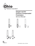
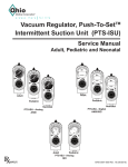
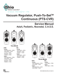
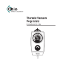
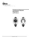
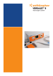
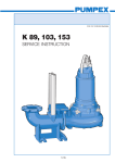
Surgical/Free-Flow Vacuum Regulators Service Manual | (On) | (On) ME D 400 100 80 500 60 200 600 40 120 Vacuum 140 -mm Hg 160 HI GH LOW 300 20 100 180 700 200 FUL L V AC Surgical/Free-Flow North American Standard North American High International High 6700-0088-000 Rev.6 1 User Responsibility Safety Instructions This manual provides you with important information about the Surgical/Free Flow Regulators. To ensure the safe and proper use of this device, READ and UNDERSTAND all of the safety and operating instructions. IF YOU DO NOT UNDERSTAND THESE INSTRUCTIONS, OR HAVE ANY QUESTIONS, REFER TO THIS SERVICE MANUAL, CONTACT YOUR SUPERVISOR, DEALER OR THE MANUFACTURER BEFORE ATTEMPTING TO USE THE DEVICE. Assurance Department. The user of this Product shall have the sole responsibility for any malfunction which results from improper use, faulty maintenance, improper repair, damage, or alteration by anyone other than Ohio Medical. AAA A 12345 This alpha character indicates the year of product manufacture and when the Serial number was assigned; “Y” = 1995, “Z” = 1996, “A” = 1997, etc. “I” and “O” are not used. Receiving / Inspection: CAUTIONS Remove product from package and inspect for damage. If product is damaged, DO NOT USE and contact your dealer or equipment provider. Only competent individuals trained in the repair of this WARNINGS This device is to be used ONLY by persons who have been properly trained on the operation of the device. Incorrect use of this device may cause serious injury to a patient. Do not use this device in the presence of flammable anesthetics. Static charges may not dissipate and a possible explosion hazard exists in the presence of these agents. This device should ONLY be used for high flow, high vacuum pressure applications. NEVER use the Surgical Free-Flow Vacuum Regulator for low flow applications. Improper vacuum levels can cause a variety of injuries. To help reduce the risk of injury, appropriate suction applications MUST be used. When using the Surgical Free Flow Device, direct contact with blood vessels and or vital organs should be avoided. Direct exposure of high vacuum levels to tissue may result in serious injury. The Surgical Free Flow Device should never be used for low flow vacuum applications, including endotracheal suctioning, nasogastric suctioning and Chest Tube suction. This Product will perform as described in this operating manual and accompanying labels and/or inserts, when assembled, operated, maintained and repaired in accordance with the instructions provided. This Product must be checked periodically. A defective product should not be used. Parts that are broken, missing, worn, distorted or contaminated should be replaced immediately. Should such repair or replacement become necessary, see the Ohio Medical service manual for service or repairs to this product. For service advice, Ohio Medical recommends that a telephone request be made to the nearest Ohio Medical Regional Service Center. This product and any of its parts should only be repaired using written instructions provided by Ohio Medical or by Ohio Medical trained personnel. The Product must not be altered without the prior written approval of Ohio Medical’s Quality 2 equipment should attempt to service it. Detailed information for more extensive repairs is included in this service manual. Not for field or transport use.* * The categories of Field and Transport Use are specifically defined in ISO 10079-3 “Field” means accidents or emergencies outside the hospital. “Transport” means use in ambulances, cars and airplanes. These situations may expose the equipment to uneven support, dirt, water, mechanical shock and temperature extremes. Ohio Medical suction equipment has not been tested to comply with the specific requirements of these categories. . MAX High Flow High Vacuum = maximum = high flow, high vacuum pressure Surgical/Free-Flow = high vacuum/high flow regulator | (On) = vacuum On O (Off) = vacuum Off mmHg = Millimeters of Mercury kPa = Kilopascal mL = Milliliter mm = Millimeter g = grams LPM = Liters per minute in = Inch o C = Degress Celsius o F = Degrees Fahrenheit DISS 6700-0088-000 Rev.6 = Diameter Index Safety System = Consult Instructions for Use Table of Contents 1/Precautions .......................................................... 4 1.1 Definitions........................................................ 4 1.2 Warnings ......................................................... 4 1.3 Cautions .......................................................... 5 1.4 Intended Use ................................................... 5 2/Scope .................................................................... 6 2.1 North American Surgical/Free-Flow Vacuum Regulators. ........................................ 6 2.2 International Surgical/Free-Flow Vacuum Regulator ......................................................... 6 3/Description and Specifications .......................... 7 3.1 Description ...................................................... 7 3.2 Specifications .................................................. 8 4/Operation.............................................................. 9 4.1 Equipment Set-up............................................ 9 4.1.1 Attaching the Overflow Safety Trap ...... 10 4.2 Mode Selection.............................................. 10 4.3 Setting the Suction Level............................... 10 4.4 Pre-use Checkout Procedure .........................11 4.5 Patient Set-up................................................ 12 5/Cleaning and Sterilization................................. 13 5.1 Cleaning ........................................................ 13 5.1.1 Routine Exterior Cleaning .................... 13 5.1.1.1 Approved Cleaning Solutions ... 13 5.1.2 Internal Component Cleaning............... 13 5.2 Sterilization .................................................... 13 7/Service - Disassembly and Assembly ............. 15 7.1 Service Tools and Equipment ........................ 15 7.2 Disassembly .................................................. 15 7.3 Assembly ....................................................... 18 8/Service Checkout Procedure............................ 19 8.1 Set-up ............................................................ 20 8.2 Flow Test ....................................................... 20 8.3 Gauge Test .................................................... 20 8.3.1 High Vacuum Gauges ONLY ................ 20 8.3.2 Standard Vacuum Gauges ONLY ......... 20 8.4 Regulation Test.............................................. 20 8.5 Bleed Test...................................................... 20 8.6 Leak Test ....................................................... 21 9/Maintenance ....................................................... 22 9.1 General Maintenance of Suction Equipment ..................................................... 22 9.2 Recommended Maintenance Schedule ........ 22 9.2.1 Maintenance Schedule ......................... 22 9.3 Repair Policy ................................................. 23 9.4 Technical Assistance ..................................... 23 9.5 Return Instructions ........................................ 23 9.6 Disposal Instructions ..................................... 23 10/Ordering Information....................................... 24 10.1 Illustrated Parts ............................................. 24 10.2 Service Kit ..................................................... 25 Appendix Installation procedure for Adapters/Probes and Fittings ............................................................A-1 6/Troubleshooting ................................................ 14 6700-0088-000 Rev.6 3 1/Precautions 1.1 Definitions Note: A Note provides additional information to clarify a point in the text. Important: An Important statement is similar to a note but of greater emphasis. CAUTION: Indicates a potentially hazardous situation, which if not avoided, could result in damage to the device or other property. WARNING: Indicates a potentially hazardous After patient use, regulators may be contaminated. Handle in accordance with your hospital’s infection control policy. Clean and disinfect all suction equipment before shipment for service to ensure transportation personnel and/or service personnel are not exposed to any hazardous contamination. Clean and disinfect all suction equipment if contaminated before disassembly, to ensure service personnel are not exposed to hazardous contamination. Following sterilization with ethylene oxide, parts situation, which if not avoided, could result in death or serious should be quarantined in a well ventilated area to allow dissipation of residual ethylene oxide gas absorbed by injury. o o the material. Aerate parts for 8 hours at 130 F (54 C). Attention. Alerts you to a warning or caution in the text. 1.2 Warnings If the vacuum regulator is repaired or disassembled in any manner, the service checkout procedure (Section 8 Service Checkout Procedure) must be performed before using the equipment on the patient. The pre-use checkout procedure (Section 4.4 Pre-use Checkout Procedure) MUST be performed BEFORE using this equipment on each patient. If the regulator fails any part of the pre-use checkout procedure, it must be removed from service and repaired by qualified service personnel. ALWAYS connect the regulator to the vacuum source and check its operation BEFORE attaching the patient connection. Connect the vacuum regulator to the vacuum source ONLY. Connection to pressure sources, even momentarily, could injure the patient or operator and damage the equipment. The fitting port of the regulator MUST be occluded when setting the prescribed suction level. This prevents the patient from receiving higher than required suction levels. DO NOT use this device in the presence of flammable anesthetics. Static charges may not dissipate and a possible explosion hazard exists in the presents of these agents. 4 6700-0088-000 Rev.6 1/Precautions 1.3 Cautions 1.4 Intended Use Cleaning the gauge may cause damage which will result in inaccurate readings. The Ohio Medical Corporation® Surgical/Free-Flow Vacuum Regulator is a vacuum-powered body fluid suction apparatus that is intended to collect and remove body fluids in High Pressure/High Flow applications; generally in surgical procedures to aspirate fluid and debris from surgical fields. DO NOT steam autoclave or liquid sterilize the Surgical/ Free-Flow Vacuum Regulator. Severe impairment to the operation of the regulator will result. The only acceptable method of sterilization is with gas (ethylene oxide). DO NOT use any Loctite® products or any products which contain methacrylate ester as an active ingredient to seal the threads on the adapters/probes and fittings. Only competent individuals trained in the repair of this equipment should attempt to service it. Sterilization with ethylene oxide mixtures may cause crazing (minute superficial cracking) of some plastic parts. Crazing will be more pronounced when mixtures containing Freon® are used. The gauge assembly MUST be handled with utmost care to retain its precision. If the lens is removed, DO NOT rest the gauge on its face. To help prevent aspirate from entering the regulator, wall outlet and pipeline equipment, a safety trap and suction filter should be attached prior to its use. Aspirate in the regulator, wall outlet and pipeline equipment may impair its operation. The use of the safety trap and suction filter will help prevent this and extend the life of the suction equipment. To prevent stripping the plastic threads, place the screw in the hole and turn counter-clockwise until it drops into the original threads, then tighten the screw. Use of lubricants other than recommended may degrade plastic or rubber components (Section 7.1 Servcice Tools and Equipment). . 6700-0088-000 Rev.6 5 2/Scope This service manual contains service, maintenance, and parts information on five models of the Surgical/ Free-Flow Vacuum Regulator: 2.1 North American Surgical/Free- 2.2 International Surgical/FreeFlow Vacuum Regulators Flow Vacuum Regulator Note: Part numbers given are for vacuum regulators without fittings or adapters. | (On) 400 300 500 200 600 High 6700-1247-900 Clockwise 0 to 700 mmHg 100 700 Note: Part numbers given are for vacuum regulators without fittings or adapters. High 6700-1248-900 Counter-clockwise 0 to 760 mmHg (0 to 101.3 kPa) | (On) ME D 80 120 140 160 HI GH LOW 100 -mm Hg 60 40 20 180 200 Standard 6700-1246-900 Clockwise 0 to 200 mmHg 6 FUL L V AC Surgical/Free-Flow 6700-0088-000 Rev.6 3/Description and Specifications and gauge from the vacuum circuit, preventing damage from aerosols and contaminants. For added durability, the regulator is housed in an impact resistant case. 3.1 Description WARNING Do not use this device in the presence of flammable anesthetics. Static charges may not dissipate and a possible explosion hazard exists in the presents of these agents. The Surgical/Free-Flow Vacuum Regulator is designed for applications in high-use areas where high flow rates and minimal maintenance requirements are of significant benefit. Flow rates of up to 150 LPM are made possible by the use of a large bore, unobstructed passage through the regulator. In place of the conventional diaphragm-valve assembly, the regulator uses a unique device called a regulating bar to control suction. During use, as the flow requirement increases, the regulator bar automatically opens to maintain suction at the preset level. When the flow requirement decreases, the regulator bar automatically closes to maintain suction at the preset level. The same mechanism compensates for changes in supply vacuum to automatically maintain the preset suction level. This unique design adds reliability and extended service life because it isolates the regulating apparatus Mode Selector Switch All models contain a vacuum gauge which indicates suction supplied by the regulator. Both High Vacuum (0 to 760 mmHg [0 to 101.3 kPa]) and Standard (0 to 200 mmHg [0 to 26.7 kPa]) options are available. The Surgical/Free-Flow Vacuum Regulator is available with a wide variety of direct mounting and bracket mounting configurations. These configurations enable the regulator to be used with virtually any centrally piped system. The regulator can be easily disassembled for maintenance and cleaning. 1. Suction Control Knob - Allows adjustment of suction to the patient. 2. Mode Selector Switch - Allows quick mode changes. a. O (Off) - No suction is supplied to the patient. b. | (On) - Suction can be adjusted with the suction control knob. 3. Vacuum Gauge - Displays the suction level to the patient during use. | (On) 400 300 Vacuum Gauge 500 200 600 Adapter Port 100 700 Suction Control Knob Wrench Fitting Port Front and Side View 6700-0088-000 Rev.6 7 3/Descriptions and Specifications 3.2 Specifications Gauge: Accuracy: ±5% of full scale deflection Flow Rate: 0 to 150 LPM without fittings at full increase setting depending on supply vacuum and open air flow. Regulated Suction Ranges: Standard Model High Models 0 to 200 mmHg (0 to 26.7 kPa) 0 to 760 mmHg (0 to 101.3 kPa) Weight: (Less Fittings) 22 oz (624 g) Dimensions: (Less Fittings) Height: 7 in (178 mm) Width: 3.5 in (89 mm) Depth: 4.6 in (117 mm) Latex Tubing, 0.25 in (6.4 mm) ID X 12 in (30 cm) supplied: 0 to full vacuum Flow dependent on source and setup Disposable tubing (Available separately in some markets; 6 mm ID X 450 mm, 750 mm and 2 m) to connect regulator and collection bottle 0 to full vacuum Flow dependent on source and setup Disposable Suction Filter: 0 to full vacuum 0 to 100 LPM @ 650 mmHg (86.7 kPa) Environmental Specifications Operating Temperature Range: 40 to 120oF (4 to 49oC) Storage Temperature Range: 0 to 160oF (-18 to 71oC) Operating and Storage Relative Humidity 5 to 95% 8 6700-0088-000 Rev.6 4/Operation 4.1 Equipment Set-up WARNINGS: Connection to positive pressure sources such as oxygen and medical air, even momentarily, could injure the patient or operator. Always connect the regulator to the vacuum source and check its operation before attaching the patient connection. CAUTIONS: Connection to positive pressure sources such as oxygen and medical air, even momentarily, could damage the equipment. If the regulator is equipped with an adapter for wall outlets, insert the adapter into the vacuum wall outlet. If the regulator is mounted elsewhere, connect a vacuum supply hose between the regulator’s adapter port and the wall outlet. Connect the collection bottle’s vacuum port to the regulator’s fitting or overflow safety trap with the appropriate vacuum tubing. Note: For proper installation of adapters/probes and fittings see Appendix A-1. Use hospital-supplied suction tubing between the vacuum regulator and the collection container, as well as between the patient port of the collection container and the patient (minimum inside diameter is 0.25 in [6 mm]). An Ohio Medical® high flow suction filter and/or overflow safety trap should be used between the collection container and regulator to prevent contamination of the regulator, wall outlet and pipeline equipment. ISO 10079-3 (Section 5.1.2.) states that “the usable volume of the collection container shall be not less than 500 mL.” High Flow Suction Filters Hydrophilic Pkg of 20 6730-0350-800 Pkg of 200 6730-0351-800 Hydrophobic Pkg of 3 Pkg of 10 Pkg of 50 Tubing x tubing nipple 6730-0570-800 6730-0571-800 6730-0572-800 Vacuum Port Vacuum Regulator 1/8” NPT x tubing nipple 6730-0580-800 6730-0581-800 6730-0582-800 Patient Port O(OFF) 400 400 300 600 500 200 600 100 100 700 Connective Tubing Disposable Suction Filter Surgical/Free-Flow Collection Bottle Underwater Seal Line 2 cm H2O Made in USA Overflow Safety Trap Equipment Set-up 6700-0088-000 Rev.6 9 4/Operation 4.1.1 Attaching the Overflow Safety Trap (OST) 4.2 Mode Selection | (On) - Suction can be adjusted with the suction control knob. CAUTION To help prevent aspirate from entering the regulator, wall outlet and pipeline equipment, a safety trap should be attached prior to its use. Aspirate in the regulator, wall outlet and pipeline equipment may impair their operation. The use of the safety trap and suction filter will help prevent this and extend the life of suction equipment. | (On) | (On) O (Off) - No suction is supplied to the patient. O (Off) Trap fitting 1. Raise the sleeve and insert the trap into the regulator fitting. 2. Turn the trap clockwise about one and a half turns to engage the threads. The trap does not need to be screwed tight; an O-ring in the regulator fitting provides a vacuum seal. The trap should rotate freely to allow the desired tubing positioning. 3. Lower the sleeve to lock the trap in position. Regulator Sleeve 3 Safety Trap 4.3 Setting the Suction Level WARNING The regulator MUST be occluded when setting the prescribed suction level so that the patient does not receive higher than required suction. 1. Clamp the connective tubing to occlude the fitting port. 2. Turn the mode selector switch to | (On). 3. Rotate the suction control knob until the vacuum gauge indicates the required setting. 3 | (On) 400 300 500 600 400 50 60 40 300 500 200 30 70 High Flow 200 High Vacuum 20 600 80 100 90 700 10 700 100 a - kP Hg - mm Surgical/Free-Flow DISS fitting 1. Insert the trap into the regulator fitting. Situate the tubing in the desired position. 2. Turn the DISS wing nut clockwise to engage the threads and tighten (there is no O-ring, so the vacuum seal depends on a tight connection). Regulator Wing Nut 3 Safety Trap 3 10 6700-0088-000 Rev.6 Clamp 100 4/Operation 7. With the tubing still clamped, increase the suction to 300 mmHg (40.0 kPa). (For the standard model, increase the suction to 100 mmHg [13.3 kPa]). 4.4 Pre-use Checkout Procedure WARNING The pre-use checkout procedure MUST be performed BEFORE using the equipment on each patient. If the regulator fails any part of the pre-use checkout procedure, it must be removed from service and repaired by qualified service personnel. 8. Slowly open and close the clamped tubing to create various flow rates through the regulator. Ensure that the suction level is maintained when the tubing is clamped. Always connect the regulator to the vacuum source and check its operation before attaching the patient connection. | (On) 400 300 500 400 50 60 40 300 500 200 30 70 High Flow 200 High Vacuum 20 80 600 600 100 90 10 700 100 100 700 - kP a Hg - mm Surgical/Free-Flow Clamp Before the vacuum regulator is used, it must be tested for correct operation as outlined below. All tests must be performed with the regulator in its normal (vertical) operating position and with a minimum supply vacuum of 450 mmHg (60.0 kPa). Release Clamp 1. Turn the mode selector switch to O (Off). 2. Rotate the suction control knob one full turn clockwise (increase). 400 300 500 400 50 300 60 70 200 600 3. Clamp tubing to occlude the fitting port. The gauge needle should not move. 9. Reduce the suction level to zero and set the mode selector switch to O (Off). O(OFF) 40 High Flow High Vacuum 80 500 30 200 O(OFF) 600 20 100 90 10 700 100 400 100 700 300 - kP a 500 -mm Hg 300 60 70 200 600 80 400 50 40 High Flow High Vacuum 500 30 700 10 700 100 - kP a Hg -mm Surgical/Free-Flow Surgical/Free-Flow Clamp 4. With the tubing still clamped, set the mode selector switch to | (On) | (On) 5. The gauge needle should not move. 400 300 500 6. Rotate the suction control knob fully anti-clockwise (decrease). 300 60 70 200 600 80 400 50 40 High Flow High Vacuum 500 30 700 200 600 20 100 90 10 700 100 100 - kP a Hg -mm Surgical/Free-Flow Clamp 6700-0088-000 Rev.6 200 600 20 100 90 11 100 4/Operation 4.5 Patient Set-up 6. Turn the mode selector switch to | (On). 1. Make sure the pre-use checkout procedure (Section 4.4 Pre-Use Checkout Procedure) has been performed. | (On) 400 300 500 600 2. Clamp the connective tubing and set the mode selector switch to | (On). 400 50 60 40 300 500 200 30 70 High Flow 200 High Vacuum 20 80 600 100 90 700 10 700 100 100 - kP a - mm Hg 3. Set the prescribed suction level. Surgical/Free-Flow WARNING The regulator MUST be occluded when setting the prescribed suction level so that the patient does not receive higher than required suction. | (On) 400 300 500 400 50 60 40 300 500 200 30 70 High Flow 200 High Vacuum 20 80 600 600 100 90 10 700 100 100 700 - kP a Hg - mm Surgical/Free-Flow Underwater Seal Line 2 cm H2O Made in USA Clamp 4. Turn the mode selector switch to O (Off). 5. Attach tubing to the vacuum port of the collection container. Patient Connective Tubing O(OFF) 400 300 500 600 400 50 300 60 40 500 200 30 70 High Flow 200 High Vacuum 600 20 80 100 90 700 10 700 100 100 - kP a - mm Hg Surgical/Free-Flow Underwater Seal Line 2 cm H2O Made in USA 12 6700-0088-000 Rev.6 Underwater Seal Line 2 cm H2O Made in USA 5/Cleaning, Disinfection and Sterilization 5.1 Cleaning and Disinfection 5.2 Sterilization WARNING Should misuse occur, resulting in accidental flooding of the regulator, the regulator may be sterilized using ethylene oxide (ETO). After sterilization, follow the instructions in Section 8 Service Checkout Procedure. After patient use, regulators may be contaminated. Handle in accordance with your hospital’s infection control policy. WARNING 5.1.1 Routine Exterior Cleaning Routine cleaning of the regulator is recommended as a standard procedure after each use. Wipe all exterior surfaces with a solution of water and mild detergent and/or an approved cleaning solution. 5.1.1.1 Approved Cleaning Solutions • Virex® (Quaternary Ammonium 0.2%): Mixture of 1 fl. oz. of Virex® to 1 gallon (128 fl. oz.) tap water using Virex®128 • Kleenaseptic® Full strength from spray can • Bleach (Sodium Hypochlorite 0.5%): Mixture of 13 fl. oz. of Clorox household bleach to 1 gallon (128 fl. oz.) tap water • Betco® TB Plus Mixture of 1 fl. oz. to 1 gallon (128 fl. oz.) tap water • Glutaraldehyde • Isopropyl Alcohol 70% • Hydrogen Peroxide 3% • Cavicide®: Ready to use full strength CAUTION Do not steam autoclave or liquid sterilize the regulator. Severe impairment to the operation of the regulator will result. The only acceptable method of sterilization is with gas (ethylene oxide). Sterilization with ethylene oxide mixtures may cause crazing (minute superficial cracking) of some plastic parts. Crazing will be more pronounced when mixtures containing Freon® are used. Note: The vacuum regulator should only be sterilized if it is contaminated or maintenance is to be performed. 1. The regulator should be sterilized with the mode selector switch in the | (On) position. 5.1.2 Internal Component Cleaning CAUTION Following sterilization with ethylene oxide, parts should be quarantined in a well ventilated area to allow dissipation of residual ethylene oxide gas absorbed by the material. Aerate parts for 8 hours at 130oF (54oC) Cleaning the gauge may cause damage which will result in inaccurate readings. 1. To disasssemble the unit, refer to Section 7 Service - Disassembly and Assembly for instructions. 2. All internal components, with the exception of the gauge, may be cleaned with a solution of warm water and mild detergent. 3. Dry all components with a lint-free cloth before assembly. 2. The only acceptable method of sterilization is with ethylene oxide. Ethylene oxide mixtures can be used at temperatures of 125 to 135°F (52 to 57°C). If this temperature cannot be obtained, room temperature sterilization with 100% ethylene oxide can also be used. Sterilization is not recommended as a standard procedure after each use. 3. After each sterilization check the condition of the filter. The filter is located just above the fitting port at the rear of the regulator. If the filter appears to have shrunk, replace it before placing the regulator back in service. Place the regulator in the vertical position and connect to a supply vacuum of 450 mmHg (60.0 kPa). 4. Perform service checkout procedure (Section 8 Service Checkout Procedure). 6700-0088-000 Rev.6 13 6/Troubleshooting Problem A. No gauge indication and no suction in any setting Possible Causes 1. No supply vacuum 2. Poor connection 3. Blocked adapter port 4. Blocked backplate 5. Blocked adapter B. No gauge indication but suction is being delivered C. Gauge indication but no suction is being delivered D. Suction level cannot be adjusted Remedy 1. Correct supply problem 2. Check all connections and seals 3. Unblock port 4. Clean with soap and water and a bottle brush 5. Unblock/replace 1. Blocked gauge pressure sensing orifice 2. Gauge mechanism locked by debris 3. Gauge mechanism damaged 4. Tubing connected to bellows is blocked or disconnected 1. Unblock orifice 1. Blocked fitting port 2. Overflow safety trap shut off 1. Unblock port 2. Reset float and/or empty overflow safety trap 3. Replace external filter 4. Replace fitting 5. Remove debris 3. Blocked external filter 4. Blocked fitting 5. Gauge mechasim locked by debris 1. Loose regulating bar 2. Tubing connected to bellows is blocked or disconnected 3. Damaged or loose valve tube 2. Remove debris 3. Replace gauge 4. Unblock or reconnect tubing 1. Tighten regulating bar 2. Unblock or reconnect tubing 3. Replace or reconnect valve tube E. Inaccurate gauge reading Note: All gauge needles should come to rest within the zero range bracket or return to the stop pin when no suction is being supplied. F. With the fitting port occluded, unable to decrease the suction level and gauge needle does not return to zero when switched to O (Off) G. Mode selector switch sticks in O (Off) or | (On) position 1. Damaged gauge 1. Replace gauge 1. Blocked filter and/or orifice 2. Damaged gauge 1. Clear orifice and replace filter 2. Replace gauge 1. Dry or damaged O-rings 1. Lubricate or replace and lubricate O-rings 2. Remove and clean mode selector switch assembly H. Insufficient flow through regulator 1. Partial blockage in wall supply 2. Contaminated passage ways 2. Partial blockage in regulator 14 6700-0088-000 Rev.6 1. Confirm wall supply open air flow meets minimum hospital requirements 2. Unblock if necessary. Perform the flow test in the service checkout procedure section of this manual (Section 8.2 Flow Test). Clear blockage if necessary. 7/Service - Disassembly and Assembly 7.1 Service Tools and Equipment 7.2 Disassembly CAUTION WARNING Use of lubricants other than recommended may degrade plastic or rubber components. The following items should be on hand during any service procedure. • Supply vacuum: 450 mmHg (60.0 kPa) minimum and 80 LPM open air flow minimum • Low vacuum calibration gauge, 225 mmHg (30.0 kPa) full scale*(Ohio Medical P/N 6700-0353-800) • High vacuum calibration gauge, 760 mmHg (101.3 kPa) full scale*(Ohio Medical P/N 6700-0352-800) • 50 LPM flowmeter(Ohio Medical; P/N 6700-0355800) • Bubble leak tester • Hexagonal allen wrench, 3/32 in • Phillips head screwdriver, No. 2 • Flat head screwdriver, 1/4 in • Open end wrench, 5/16 in • Tweezers (filter remover) • Wooden toothpick (O-ring remover) • Dow Corning® 111 grease Ohio Medical P/N 67000074-200) • Tubing clamp • Bottle brush If the vacuum regulator is repaired or disassembled in any manner, the service checkout procedure (Section 8 Service Checkout Procedure) must be performed before using the equipment on the patient. Clean and sterilize all suction equipment if contaminated before disassembly, to ensure service personnel are not exposed to hazardous contamination. CAUTION The gauge assembly must be handled with utmost care to retain its precision. If the lens is removed, DO NOT rest the gauge on its face. 6700-0088-000 Rev.6 15 7/Service - Disassembly and Assembly 10 12 18 14 13 9 11 13 16 14 16 15 17 14 13 19 8 20 12 6 7 5 4 3 2 1 ) 1. 2. 3. 4. 5. 6. 7. 8. 9. 10. 11. 12. 13. 14. 15. 16. 17. 18. 19. 20. 21. 22. 23. 24. 25. 26. 27. 28. 29. 30. 31. 32. 33. 16 Screw, Socket Head Cap, 4-40 x 1/2” Locking Cam Washer, Flat .28” OD, .125” ID Spring Washer Increase Label Control Knob Regulator Cover Control Shaft Snap Fit Lens O-rings (2), Gauge Gauge Assembly (Includes gauge, O-rings, and lens) Tubing, .125” OD (2) Adapter (3) O-ring (3) Bellows Nut, Elastic Stop, 6-32 (4) O-ring, 2-010, Buna-N (2) Surgical/Free-Flow Base Bottom Connector Screw, Flat Head 6-32 X 1/2” (2) Selector Switch Assembly Washer, Flat Screw, Buttonhead Cap, 8-32 X 5/16” Inlet Connector, Universal Screw, Round Head 6-32 X 7/8” (2) Filter Screw, No. 6 Pan Head (4) 30 Valve Tube Regulating Bar Screw, Buttonhead Cap 8-32 X 3/8” (4) Rear Window 33 Tubular Speed Clip Locking Knob | (O n Item & Description 21 16 22 23 24 17 18 25 26 30 27 (4 required) 29 28 31 32 6700-0088-000 Rev.6 7/Service - Disassembly and Assembly 1. Remove the four screws located at the corners of the back cover. Hold the regulator with the front cover and knob facing upward. Rotate the suction control knob clockwise until the cover/knob assembly is free of the rest of the regulator. 2. Unscrew the cap screw from the suction control knob on the front cover. Pull the suction control knob off. 3. Carefully pull the gauge assembly out of its mount on the base. The snap fit lens can also be removed (If applicable). Pull down plastic tab with right index finger whuile holding gauge frame with left hand. Snap Fit Lens Removal 4. Remove the two small tubes which are connected from the bellows to the base. 5. Use the locking wrench to remove the two screws holding the rear window in place. Remove the window. 6. Locate the regulating bar inside the recessed enclosure. Unscrew the two retaining screws and remove the regulating bar and bellows. 7. Remove the valve tube from the recessed enclosure. 8. Remove the adapter and fitting ports and associated O-rings. 9. Pull the internal filter out of the socket using a pair of tweezers. 10. Loosen the screw that holds the selector switch assembly in position and pull the selector switch assembly out of the base. 6700-0088-000 Rev.6 Detail Back Cover 17 7/Service - Disassembly and Assembly 7.3 Assembly CAUTION To prevent stripping the plastic threads, place the screw in the hole and turn counter-clockwise until it drops into the original threads, then tighten the screw. 1. Lubricate the adapter and fitting port O-rings. Assemble the adapter and fitting ports with appropriate O-rings to the base. 8. Place the knurled end of the control shaft through its hole in the front cover and slide the suction control knob onto the shaft. Place the curved spring washer and flat washer in the center hole of the knob. 9. Start the cap screw in the hole. Run the screw all the way in until the knob is locked in position. The locking cam should be in place on the screw head so that it seats against the tab in the control knob from a clockwise direction. 3. Connect the valve tube and install the bellows and regulating bar to the base. 10. Loosen the cap screw one turn counter-clockwise until the cam hits the tab on the control knob. If the suction control knob does not turn freely, loosen the cap screw. 4. Install the rear window. Use the locking wrench to tighten the two screws. 11. Hold the base assembly with the bellows and gauge facing upward. 5. Connect the two small tubes from the bellows to the base. 12. Place the cover over the base and engage the control shaft with the bellows by turning the suction control knob counter-clockwise. 2. Install a new filter. 6. Lubricate the selector switch assembly O-rings and fit into the base assembly. Tighten the retaining screw which holds the selector switch assembly in place. To prevent damage to the plastic base, do not over tighten the screw. 7. Lubricate the gauge assembly O-rings. Fit the gauge into the base assembly. 18 13. Install the four cover screws. To prevent stripping the plastic threads, place the screw in its hole and turn counter-clockwise until it drops into its original threads, then tighten the screw. 14. Perform the service checkout procedure (Secton 8 Service Checkout Procedure) before returning the regulator to service. 6700-0088-000 Rev.6 8/Service Checkout Procedure WARNING If the vacuum regulator is repaired or disassembled in any manner, the service checkout procedure must be performed before using the equipment on a patient. Important: This entire service checkout procedure must be performed in numerical order. Mode Selector Switch | (On) Supply Vacuum Gauge 0 to 760 mmHg (0 to 101.3 kPa) 400 300 Vacuum 500 200 600 100 700 Vacuum Regulator Supply Vacuum Suction Control Knob 450 mmHg (60.0 kPa) minimum and open flow of 80 LPM minimum Occluded High Vacuum Calibration Gauge 760 mmHg (101.3 kPa) Flowmeter 50 LPM Low Vacuum Calibration Gauge 225 mmHg (30.0 kPa) Service Checkout Tests 6700-0088-000 Rev.6 19 8/Service Checkout Procedure 8.1 Set-up 8.3.2 Standard Vacuum Gauge ONLY 1. Verify that there is a minimum of 450 mmHg (60.0 kPa) vacuum on the supply gauge. 1. Connect the regulator’s fitting port to the low calibration gauge with tubing. 2. The supply open flow must be 50 LPM minimum. 2. Set the mode selector switch to | (On). 3. Connect the supply vacuum to the adapter port. 3. Ensure that the gauge is in agreement with the low vacuum calibration gauge within the ± 10 mmHg (± 1.3 kPa) tolerance. Recommended test points are 40, 80, and 140 mmHg. (5.3, 10.7, and 18.7 kPa) 8.2 Flow Test 1. Connect the regulator’s fitting port to the flowmeter with tubing. 2. Set the mode selector switch to | (On) and rotate the suction control knob fully clockwise (increase). 3. Verify that the flow rate exceeds 30 LPM. 8.4 Regulation Test 1. Disconnect the calibration gauge and occlude the fitting port. 2. Depending on the type of regulator, perform one of the following. 4. Set the mode selector to O (Off). 5. Disconnect the flowmeter. 8.3 Gauge Test Note: All Ohio Medical gauges are supplied with an accuracy of ±5% of full scale deflection throughout their range. The table below is provided for reference. Gauge Standard Vacuum Range 0 to 200 mmHg (0 to 26.7 kPa) Tolerance ± 10 mmHg (± 1.3 kPa) High Vacuum 0 to 760 mmHg (0 to 101.3 kPa) ± 38 mmHg (± 5.1 kPa) Note: All gauge needles should come to rest within the zero range bracket or return to the stop pin when no suction is being supplied. Gauge needles which do not comply may be out of calibration. When checking gauge accuracy, be sure that the calibration gauge has an accuracy of 1% of full scale deflection or better. 8.3.1 High Vacuum Gauges ONLY 1. Connect the regulator’s fitting port to the high calibration gauge with tubing. a. If using a high vacuum regulator (North American or International), set the gauge to 300 mmHg (40.0 kPa). b. If using a standard vacuum regulator (North American), set the gauge to 100 mmHg (13.3 kPa). 3. Open and close the fitting port several times. 4. With the fitting port occluded, the gauge should return to the setting listed in step 2 within a tolerance of: ± 38 mmHg (± 5.1 kPa) for the high vacuum gauge or ± 10 mmHg (± 1.3 kPa) for the standard vacuum gauge 8.5 Bleed Test 1. Occlude the fitting port and set the vacuum level to 100 mmHg (13.3 kPa). 2. Set the selector switch to O (Off) and observe the gauge needle. It must return to the zero range bracket or stop pin within 10 seconds. 2. Turn the mode selector switch to | (On). 3. Ensure that the gauge is in agreement with the high vacuum calibration gauge within the ± 38 mmHg (± 5.1 kPa) tolerance. Recommended test points are 100, 300, and 400 mmHg (13.3, 40.0, and 53.3 kPa). 20 6700-0088-000 Rev.6 8/Service Checkout Procedure 8.6 Leak Test 1. Set the mode selector switch to O (Off). 2. Connect the regulator fitting port to the bubble leak tester port A with tubing. 3. Rotate the suction control knob 1/2 turn in the clockwise (increase) direction. 4. Observe the bubble leak tester. No bubbles should appear. 5. Rotate the suction control knob fully in the counterclockwise (decrease) direction. 6. Set the mode selector switch to | (On). 7. Observe the bubble leak tester. No bubbles should appear. Mode Selector Switch O (OFF) 400 300 Vacuum 500 200 600 100 700 Port B Vacuum Regulator Port A Suction Control Knob Sealed 1/4” ID Clear Tubing with Knife Edge 1.0 in Water Bubble Leak Tester Bubble Leak Test Set-up 6700-0088-000 Rev.6 21 9/Maintenance Routine maintenance and inspection are important to the performance of suction equipment. The following is a recommended list for care of suction equipment after each patient use. 9.1 General Maintenance of Suction Equipment WARNINGS The pre-use checkout procedure (Section 4.4 Pre-use Checkout Procedure) must be performed before using this equipment on each patient. If the regulator fails any part of the pre-use checkout procedure, it must be removed from service and repaired by qualified service personnel. To reduce service personnel exposure to hazardous contamination, clean and disinfect all suction equipment before disassembly. Surgical/Free-Flow Vacuum Regulators should be kept in use or used on a rotating basis. Unused equipment may tend to deteriorate. Maintenance of the vacuum piping system is as important as maintenance of the suction equipment. The use of collection bottles with reliable shut-off valves, overflow safety trap assemblies and disposable suction filters will protect the regulator and piping system. The flow rate at the wall outlet should be checked on a yearly basis and suitable cleaning of the outlets should be performed. The flow rate measurement should meet local standards. 1. Perform a thorough cleaning by washing all bottles, tubing, metal connectors, etc, and removing all residue. 2. Wipe all exterior surfaces with a solution of water and mild detergent. 3. Perform a careful visual inspection. 4. Check that the high flow disposable suction filter is clean and in good condition. 5. Check that all tubing is in good condition and connected securely to the correct ports. 6. Check the floats in the overflow safety trap and collection bottle for correct operation. 7. Perform the pre-use checkout procedure. 9.2 Recommended Maintenance Schedule In addition to the pre-use checkout procedure, the following periodic maintenance should be performed. 9.2.1 Maintenance Schedule Item Minimum Frequency Comments Service Checkout Procedure Every 4 months O-Rings Inspect every 4 months; Replace every 24 months If the regulator does not pass the service checkout procedure (Section 8 Service Checkout Procedure), refer to Section 6 Troubleshooting of this manual. Repair as necessary. Replace as necessary to minimize in use failures. Internal Filters Inspect every 4 months; Replace as necessary. Replacement interval will depend greatly on hours of usage and condition of operating environment. Valve Tube Inspect every 4 months Replace as necessary High Flow Disposable Suction Filter Replace after each patient use Replace more frequently if flow deteriorates 22 6700-0088-000 Rev.6 9/Maintenance 9.3 Repair Policy 9.5 Return Instructions WARNING 1. Call for a Return Material Authorization (RMA) number before sending any items for warranty and/ or non-warranty repair. (1-866-549-6446) Clean and disinfect all suction equipment before shipment for service to ensure transportation personnel and/or service personnel are not exposed to any hazardous contamination. CAUTIONS Do not steam autoclave or liquid sterilize the Surgical/Free-Flow Vacuum Regulator. Severe impairment to the operation of the regulator will result. The only acceptable method of sterilization is with gas (ethylene oxide). Only competent individuals trained in the repair of this equipment should attempt to service it. Do not use malfunctioning equipment. Make all necessary repairs. Have the equipment repaired by qualified service personnel or by Ohio Medical. Parts listed in the service manual for this product may be repaired or replaced by a competent, trained person who has experience in repairing devices of this nature. After repair, perform the service checkout procedure (Section 8 Service Checkout Procedure) to ensure that it is functioning properly, and complies with the published specifications. 9.4 Technical Assistance 2. Clean and sterilize the vacuum regulator. 3. Package the vacuum regulator securely for protection, preferably in the original container. 4. Include a letter describing in detail any difficulties experienced with the vacuum regulator. Include the person, title, and telephone number to contact for functional questions. 5. If the vacuum regulator is under warranty, include the warranty information that came with the device and a copy of the invoice. 6. Include a purchase order to cover repair of a regulator not under warranty. 7. Ship the vacuum regulator prepaid. Write your return address and billing address information on the package or letter that comes with the package. For U.S.A. Warranty and Non-Warranty Repairs, mail the package to: Ohio Medical Corporation 1111 Lakeside Drive Gurnee, IL 60031 RMA #________________ If technical assistance is required, contact Ohio Medical technical support listed on the back cover. In other locations contact your nearest Ohio Medical office or authorized Ohio Medical distributor. 9.6 Disposal Instructions Dispose of vacuum regulator in accordance with local regulations. 6700-0088-000 Rev.6 23 10/Ordering Information 10 12 14 18 10 9 11 13 16 14 16 17 8 19 14 15 13 20 12 10.1 Illustrated Parts Item & Description 1. 2. 3. 4. 5. 6. 7. 8. 9. 10. 11. 12. 13. 24 Part Number Screw, Socket Head Cap, 4-40 X 1/2” .................................6700-0170-400 Locking Cam ................................0212-1705-300 Washer, Flat .28” OD, .125” ID .....6700-0174-400 Washer, Spring .............................6700-0148-400 Increase Label North American ..........................6700-0250-100 International ...............................0206-5154-300 Control Knob ................................0206-5187-300 Regulator Cover ...........................6700-0198-500 Control Shaft ................................0206-5188-300 Snap Fit Lens ...............................6700-0087-500 O-rings (2), Gauge .......................6700-0130-500 Gauge Assembly (Includes gauge, O-ring, and lens) North American Standard...........6700-0050-200 North American High ..................6700-0050-201 International High .......................6700-0050-204 Tubing, .125” OD (2) ....................0206-5186-300 Adapter (3) ...................................6700-0173-400 7 6 5 4 3 2 1 14. O-ring (3) ......................................0210-0593-300 15. Bellows Assembly (Includes bellows, adapters and O-rings) ..................6700-0165-700 16. Nut, Elastic Stop, 6-32 (4) ............6700-0175-400 17. O-ring (2) ......................................6700-0131-500 18. Base Assembly (Includes base, adapter, and serial number label) North American ..........................6700-0161-700 International ...............................6700-0162-700 19. Bottom Connector..........................0206-5195-300 20. Screw, Flat Head 6-32 X 1/2” (2) ...6700-0171-400 6700-0088-000 Rev.6 10/Ordering Information | (O n) 21 16 22 23 17 24 18 25 26 30 27 (4 required) 29 28 30 31 32 33 Item & Description Part Number 21. Selector Switch Assembly North American ..........................6700-0067-700 International ...............................6700-0067-701 22. Washer, Flat .................................6700-0164-400 23. Screw, Buttonhead Cap, 8-32 X 5/16” ...............................6700-0165-400 24. Inlet Connector, Universal ............0206-5149-300 25. Screw, Round Head 6-32 X 7/8” (2) ............................6700-0176-400 26. Filter .............................................0206-5181-300 27. Screw, No. 6 Pan Head (4)...........6700-0151-400 28. Valve Tube....................................0206-5182-300 29. Regulating Bar..............................0206-5183-300 30. Screw, Buttonhead Cap 8-32 X 3/8” (4) ............................6700-0172-400 31. Rear Window ................................0206-5180-300 32. Tubular Speed Clip .......................0206-5163-300 33. Locking Knob................................0212-1932-300 10.2 Service Kit Selector Switch Assembly Replacement Kit, ..................................................... 6700-0013-200 Kit includes: Buttonhead Screw, 8-32 Flat Washer Selector Switch Assembly 6700-0088-000 Rev.6 25 Appendix Installation procedure for Adapters/Probes and Fittings. CAUTION Do not use any Loctite® products or any products which contain methacrylate ester as an active ingredient to seal the threads on the adapters/ probes and fittings. All adapters/probes and fittings should be sealed and installed properly to prevent leaks and to support the equipment when mounted. Both vacuum regulator ports are 1/8-27 NPTF tapered pipe threads. It is important to note that adapters/probes and fittings seal on the thread and may have threads exposed after they have been tightened properly. The torque range for installing adapters/probes and fittings is 4.0 ft-lb (5.4 N-m) minimum to 10.0 ft-lb (13.6 N-m) maximum. Prior to installing the adapter/probe or fitting, seal the thread with Teflon® (PTFE) tape or one of the following lubricants: Adapters/probes and fittings which are not keyed for specific orientation, should be torqued to approximately 6.0 ft-lb (8.1 N-m). Dow Corning® 111 (Ohio Medical P/N 6700-0074-200) Adapters/probes and fittings that are keyed to specific orientation, must be torqued initially to 4.0 ft-lbs. Additional torque is applied only until orientation is correct. Ball Vac Kote® (37951M) (Ohio Medical P/N 02200091-300) A-1 26 6700-0088-000 Rev.6 Notes 6700-0088-000 Rev.6 27 North America United States Customer Service, Distribution Center Technical Support, Sales and Service Equipment Service Center Ohio Medical Corporation 1111 Lakeside Drive Gurnee, IL 60031 USA P: +1 866 549 6446 P: +1 847 855 0500 F: +1 847 855 6218 EC REP OxygenCare Ltd. 2 Holfeld Business Park Kilmacanogue Co Wicklow Ireland Tel: +353 1 2769700 Fax: +353 1 2764970 © 2013 Ohio Medical Corporation. This document contains information that is proprietary and confidential to Ohio Medical Corporation. Use of this information is under license from Ohio Medical Corporation. Any use other than that authorized by Ohio Medical Corporation is prohibited. Ohio Medical Corporation is a registered trademark and Push-to-Set is a trademark of Ohio Medical Corporation. ISO is a registered trademark of International Organization for Standardization. Vac Kote is a registered trademark of the Ball Aerospace & Technology Corp. Loctite is a registered trademark of Henkel Corporation. Teflon and Freon are registered trademarks of E.I. du Pont de Nemours and Company. Cavicide is a registered trademark of Metrex Research Corporation. Virex is a registered trademark of S.C. Johnson & Son, Inc. Kleenaseptic is a registered trademark of Metrex Research Corporation. Betco is a registered trademark of Betco Corporation. 28 6700-0088-000 Rev.6 04/2013