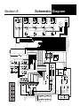
1
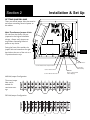
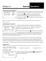
ILM001E June, 2000 Price $5.50 USD Operation Manual Drawn Arc Stud Welding Power Source SW1200 & SW2000 BE SURE THIS INFORMATION REACHES THE OPERATOR. EXTRA COPIES ARE AVAILABLE THROUGH YOUR SUPPLIER. CAUTION THESE INSTRUCTIONS ARE FOR EXPERIENCED OPERATORS. If you are not fully familiar with the principles of operation and safe practices for arc welding equipment, we urge you to read AWS SP “Safe Practices” available from the American Welding Society. Do NOT permit untrained persons to install, operate, or maintain this equipment. Do NOT attempt to install or operate this equipment until you have read and fully understand these instructions. If you do not fully understand these instructions, contact your supplier for further information. Be sure to read the Safety Precautions before installing or operating this equipment. Table of Contents SECTION 1: Safety Precautions 3 SECTION 2: Set Up 7 SECTION 3: Normal Operation Basic Auto Weld Advanced Features SECTION 4: 10 12 14 Optional Features Preset Memory Gas Data Recorder Multi-Gun 18 20 20 23 SECTION 5: Special Techniques 24 SECTION 6: Trouble Shooting 29 SECTION 7: System Maintenance 32 SECTION 8: Schematic Diagram 33 SECTION 9: Part List 34 APPENDIX A: Menu Trees 36 USERS RESPONSIBILITY This equipment will perform in conformity with the description contained in this manual and accompanying labels and/or inserts when installed, maintained and repaired in accordance with the instructions provided. This equipment must be checked periodically. Defective equipment should not be used. Parts that are broken, missing, worn, distorted or contaminated should be replaced immediately. Should such repair or replacement become necessary, the manufacturer recommends that a telephone or written request for service advice be made to the Authorized Distributer from whom purchased. This equipment or any of it’s parts should not be altered without the prior written approval of the manufacturer. The user of this equipment shall have the sole responsibility for any malfunction which results from improper use, faulty maintenance, damage, improper repair or alteration by anyone other than the manufacturer or a service facility designated by the manufacturer. 2 Section 1 Table o Safety Precautions WARNING: These Safety Precautions are for your protection. They summarize precautionary information from the references listed in the Additional Safety Information section. Before performing any installation or operating procedures, be sure to read and follow the safety precautions listed below as well as all other manuals, material safety data sheets, labels, etc. Failure to observe Safety Precautions can result in injury or death. PROTECT YOURSELF AND OTHERS Some welding, cutting, and gouging processes are noisy and require ear protection. The arc, like the sun, emits ultraviolet (UV) and other radiation and can injure skin and eyes. Hot metal can cause burns. Training in the proper use of the processes and equipment is essential to prevent accidents. Therefore: 1) 2) 3) 4) 5) 6) Always wear safety glasses with side shields in any work area, even if welding helmets, face shields and goggles are also required. Use a face shield fitted with the correct filter. Cover sparks and rays of the arc when operating or observing operations. Warn bystanders not to watch the arc and not to expose themselves to the rays of the electric-arc or hot metal. Wear flameproof gauntlet type gloves, heavy long-sleeve shirt, cuffless trousers, high topped shoes, and a welding helmet or cap for hair protection, to protect against arc rays and hot sparks or hot metal. A flameproof apron may also be desirable as protection against radiated heat and sparks. Hot sparks or metal can lodge in rolled up sleeves, trousers cuffs or pockets. Sleeves and collars should be kept buttoned, and open pockets eliminated from the front of clothing. Protect other personnel from arc rays and hot sparks with a suitable non-flammable partitions or curtains. Use goggles over safety glasses when chipping slag or grinding. Chipped slag may be hot and can fly far. Bystanders should also wear goggles over safety glasses. FIRES AND EXPLOSIONS Heat from flames and arcs can start fires. Hot slag or sparks can also cause fires and explosions. Therefore: 1) 2) 3) 4) 5) Remove all combustible materials well away from the work area or cover the materials with a protective nonflammable covering. Combustible materials include wood, cloth, sawdust, liquid and gas fuels, solvents, paints and coatings, paper, etc. Hot sparks or hot metal can fall through cracks or crevices in floors or wall openings and cause a hidden smoldering fire or fires on the floor below. Make certain that such openings are protected from hot sparks and metal. Do not weld, cut, or perform other hot work until the work piece has been completely cleaned so that there are no substances on the work piece which might produce flammable or toxic vapors. Do not do hot work on closed containers. They may explode. Have appropriate fire extinguishing equipment handy for instant use, such as a garden hose, water pail, sand bucket or portable fire extinguisher. Be sure you are trained for proper use. Do not use equipment beyond its ratings. For example, overloaded welding cable can overheat and create a fire hazard. 3 6) 7) After completing operations, inspect the work area to make certain there are no hot sparks or hot metal which could cause a later fire. Use fire watchers when necessary. For additional information, refer to NFPA Standard 51B, “Fire Prevention in Use of Cutting and Welding Processes,” available from the National Fire Protection Association,Batterymarch Park, Quincy, MA 02269 ELECTRICAL SHOCK Contact with live electrical parts and ground can cause severe injury or death. DO NOT use welding current in damp areas, if movement is confined, or if there is danger of falling. 1) 2) 3) 4) 5) 6) 7) 8) 9) Be sure the power source frame (chassis) is connected to the ground system of the input power. Connect the work piece to a good electrical ground. Connect the work cable to the work piece. A poor or missing connection can expose you or others to a fatal shock. Use well-maintained equipment. Replace worn or damaged cables. Keep everything dry, including clothing, work area, cables, torch/electrode holder and power source. Make sure that all parts of your body are insulated from work and from the ground. Do not stand directly on metal or the earth while working in tight quarters or a damp area; stand on dry boards or an insulating platform and wear rubber-soled shoes. Put on dry, hole-free gloves before turning on the power. Refer to ANSI/ASC Standard Z49.1 (listed on page 6) for specific grounding recommendations. Do not mistake the work lead for a ground cable. ELECTRIC AND MAGNETIC FIELDS Electric and magnetic fields may be dangerous. Electric current flowing through any conductor causes localized Electric and Magnetic Fields (EMF). Welding and cutting current creates EMF around welding cables and welding machines. Therefore: 1) 2) 3) Welders having pacemakers should consult their physician before welding. EMF may interfere with some pacemakers. Exposure to EMF may have other health effects which are unknown. Welders should use the following procedures to minimize exposure to EMF: A) Route the electrode and work cables together. Secure them with tape when possible. B) Never coil the torch or work cable around your body. C) Do not place your body between the torch and work cables. Route cables on the same side of your body. D) Connect the work cable to the work piece as close as possible to the area being welded. E) Keep welding power source and cables as far away from your body as possible. FUMES AND GASES Fumes and gases can cause discomfort or harm, particularly in confined spaces. Do not breathe fumes and gases. Shielding gases can cause asphyxiation. Therefore: 1) 2) 3) 4) Always provide adequate ventilation in the work area by natural or mechanical means. Do not weld, cut, or gouge on materials such as galvanized steel, stainless steel, copper, zinc, lead, beryllium, or cadmium unless positive mechanical ventilation is provided. Do not breathe fumes from these materials. Do not operate near degreasing and spraying operations. The heat or arc rays can react with chlorinated hydrocarbon vapors to form phosgene, a highly toxic gas, and other irritant gasses. If your develop momentary eye, nose, or throat irritation while operating, this is an indication that ventilation is not adequate. Stop work and take necessary steps to improve ventilation in the work areas. Do not continue to operate if physical discomfort persists. Refer to ANSI/ASC Standard Z49.1 (see listing on next page) for specific ventilation recommendations. 4 CYLINDER HANDLING Cylinders, if mishandled, can rupture and violently release gas. Sudden rupture of cylinder, valve, or relief device can injure or kill. Therefore: 1) 2) 3) 4) 5) Use the proper gas for the process and use the proper pressure reducing regulator designed to operate from the compressed gas cylinder. Do not use adaptors. Maintain hoses and fittings in good condition. Always secure cylinders in an upright position by chain or strap to suitable hand trucks, undercarriages, benches, walls, post, or racks. Never secure cylinders to work tables or fixtures where they may become part of an electrical circuit. When not in use, keep cylinder valves closed. Have valve protection cap in place if regulator is not connected. Secure and move cylinders by using suitable hand trucks. Avoid rough handling of cylinders. Locate cylinders away from heat, sparks, and flames. Never strike an arc on a cylinder. For additional information, refer to CGA Standard P-1, “Precautions for Safe Handling of Compressed Gases in Cylinders”, which is available from Compressed Gas Association, 1235 Jefferson Davis Highway, Arlington, VA 22202 EQUIPMENT MAINTENANCE Faulty or improperly maintained equipment can cause injury or death. Therefore: 1) 2) 3) 4) 5) 6) Always have qualified personnel perform the installation, troubleshooting, and maintenance work. Do not perform any electrical work unless you are qualified to perform such work. Before performing any maintenance work inside a power source, disconnect the power source from the incoming electrical power. Maintain cables, grounding wire, connections, power cord, and power supply in safe working order. Do not operate any equipment in faulty condition. Do not abuse any equipment or accessories. Keep equipment away from: - heat sources such as furnaces - wet conditions such as water puddles and inclement weather - oil or grease - corrosive atmospheres. Keep all safety devices and cabinet covers in position and in good repair. Use equipment only for its intended purpose. Do not modify it in any manner. ELECTRICALLY POWERED EQUIPMENT Faulty or improperly electrified equipment can cause injury or death. Therefore: 1) 2) 3) 4) Always have qualified personnel perform the installation, troubleshooting, and maintenance work. Do not perform any electrical work unless you are qualified to perform such work. Before performing any work inside a power source, disconnect the power source from the incoming electrical power using the disconnect switch at the fuse box before working on the equipment. Install equipment in accordance with the U.S. National Electrical Code, all local codes and the manufacture’s recommendations. Ground the equipment in accordance with the U.S. National Electrical Code and the manufacturer’s recommendations. 5 MOVING PARTS CAN CAUSE INJURY Electric fan can start at any time without warning and cause severe injury, therefore: 1) 2) 3) 4) 5) Always disconnect electrical power prior to service to prevent the fan from starting unexpectedly. Keep all doors, panels, covers, and guards closed and securely in place. Have only qualified people remove guards or covers for maintenance and troubleshooting as necessary. Keep hands, hair, loose clothing, and tools away from moving parts. Reinstall panels or guards and close doors when servicing is finished and before re-energizing welder. ADDITIONAL SAFETY INFORMATION For more information on safe practices for electric arc welding refer to the following publications: The following publications, which are available form the American Welding Society, 550 N.W. LeJuene Road, Miami, FL 33126, are recommended to you: 1) ANSI/ASC Z49.1 - “Safety in Welding and Cutting” 2) AWS C5.1 - “Recommended Practices for Plasma Arc Welding” 3) AWS C5.6 - “Recommended Practices for Gas Metal Arc Welding” 4) AWS SP - “Safe Practices” - Reprint, Welding Handbook. 5) ANSI/AWS F4.1, “Recommended Safe Practices for Welding and Cutting of Containers That Have Held Hazardous Substances.” This symbol appearing throughout this manual means ATTENTION! BE ALERT! Your safety is involved. The following definitions apply to DANGER, WARNING, CAUTION found throughout this manual. DANGER Used to call attention to immediate hazards which, if not avoided, will result in immediate, serious personal injury or loss of life. WARNING Used to call attention to potential hazards which could result in personal injury or lost of life. CAUTION Used to call attention to hazards which could result in minor personal injury. 6 Section 2 Installation & Set Up Location The power supply should be located: On a flat, level floor. Near the work area to limit welding cable length (shorter lengths are preferred). In a dry area away from moisture. Placed to protect it from grinding dust and other contaminates. To provide min. 12 clearance on all sides for cooling. Such that the leg openings and the area between the legs is not blocked (again for cooling). Electrical DANGER ALL Electrical connections should be made by a properly certified electrical professional. It is recommended that a line disconnect switch be installed in the input circuit to the welding power source. This provides a safe and convenient means to completely remove all electrical power from the welding power supply whenever it is necessary to perform any work on it Before making the electrical input connections to the welding power source, machinery lockout procedures should be employed. If the connection is to be made from a line disconnect switch, the switch should be padlocked in the open position. If the connection is made from a fuse box, remove the fuses from the box and padlock the cover in the closed position. If the unit is connected to a circuit breaker, or other disconnecting device without locking facilities, attach a red tag to the device to warn others that the circuit is being worked on. Connect the input conductors to the welding power source before making connections to the three-phase input voltage. Check the input voltage jumper link arrangement on the main weld transformer and control transformer to make sure the transformer is connected correctly for the incoming line voltage. The ground terminal is connected to the welding power supply frame and is for grounding purposes only. Do not connect a conductor from the ground terminal to any of the line terminals. This will result in an electrically energized (HOT) power supply frame. Always connect the input grounding conductor to the long 1/4-20 stud on the base panel f irst. This stud will already have green or green with yellow stripe wires connected to it. Fusing / Cable Recommendations SW1200 Guage 230 V 100A 1 460 V 50A 4 SW2000 150A 75A Guage 1/0 2 All Disconnect Fuses should be delay type The red, black and white wires on the incoming cable do not need a termination. The green (or green with yellow stripe) ground wire will need a ring terminal with a 1/4 clearance hole. 7 Section 2 Installation & Set Up SETTING JUMPER LINKS There are several jumper links that must be set before connecting electrical power to the welder. Main Transformer Jumper Links All units from the factory are prejumpered to the highest selectable voltage. Always verify jumper settings before connecting electrical power to any device. Facing the front of the welder, the jumper links are located on the right hand side at the rear of the unit on a 12 position barrier strip. L1 L2 L3 Input Contactor Control Transformer Jumper Links Control Transformer Control Transformer Fuse 460 Volt Jumper Configuration The extra jumper links can be stacked for convienent storage. 230 Volt Jumper Configuration 8 12 Position Barrier Strip GND/PE Green or Green With Yellow Stripe(s) Section 2 Installation & Set Up Control Transformer Similar to the main transformer, the control transformer also has configurable jumper links. These are located directly on the control transformer on the side nearest the front of the unit. The control transformer is located at the top of the axillary module (see diagram on preceeding page) which also houses the contactor and the main transformer jumper block. There are two wires connected to the control transformer terminals H1 and H4. These wires must remain attached after configuring the control transformer jumper links. 230 Volt Configuration 460 Volt Configuration For the 460V configuration, the extra jumper link may be secured to the #10-24 stud located on the base pan in front of the 12 position barrier strip. Connecting Incoming Power To connect incoming electrical power it is necessary to remove the right side cover. Remove the screws retaining the right side panel (Use a 3/8 nut runner, or a large flat blade screw driver). Strip back the outer cable jacketing so WARNING socket there is approximately 4 of insulated leads. Strip approximately ½ of insulation on each conductor. Crimp a lug with a ¼ hole onto the green conductor. Thread the 4 leads through the cord grip on the lower left hand side of the back of the welder. Connect the red, white and black wires to L1, L2 and L3 on the contactor. Use a large flat bladed screwdriver to secure the incoming leads to the contactor. These connections should be tight. Tighten cord grip onto incoming cable jacket. Connect the ground lead to the long bolt on the floor pan as shown in the diagram on the right. There is already a green with yellow stripe wire attached to this bolt. Trap this lug between the two nuts and tighten the nuts. 9 Section 3 Normal Operation Controls Diagram Upper Rotary Knob Scroll Up Lower Rotary Knob Lock Scroll Down Flow Enabled Gas Control Memory Presets (8) Display Scroll Right Active LED Data Module Control Serial Port Auto Weld Reset Home Auto/Man Manual Feed Feed Error Weld Error Manual Weld Gun 1 Gun 2 Gun 3 Gun 4 Power Switch Some features shown are optional. Screen Conventions Welder Function Data Line #1 Data Line #2 Information Line 1 Welder Function Line 2 Data Line Controlled by Upper Rotary Knob Line 3 Data Line Controlled by Lower Rotary Knob Line 4 Information (Maintenance Required, more info on next screen, locked/unlocked) Display Backlighting To extend display life, the backlight will turn off after a few minutes. This is normal. The next button push or knob turn will light the backlight again. Home Screen Normal Operate GUN1 Main Current 550A Main Time 0.250S The Home screen is either the Normal Operaion screen or the Auto weld screen depending on the selected mode. To weld the home screen must be showing. You can always reach this screen (except when entering or changing a password) by depressing the home button on the front panel. If the welder is left in some other screen the unit will automatically return to the home screen after a short time. 10 Section 3 Normal Operation POWER UP Press (to the right or towards the 1) and momentarily hold the power switch, located on the lower left side of the control panel. SmartWeld 1200 60Hz The power supply initiates a self test. This test lasts approximately 5 Version 1.7 seconds. During this test routine none of the welderss functions, Build 1238 including welding, will operate. This is normal. The test will verify system Selftest...OK RAM and system ROM. At the end of the test it will display OK if all functions check out. If the system has a malfunction, the display will show a failure and the system will not operate. During the self test all system LEDs will light so the operator can verify that the LEDs are working. Note: your screen may be slightly different. When self test ends, the display will automatically show the home screen (the Normal Operate or Auto Weld screen depending in which mode the unit was left). Any values in main current or main time are saved from the last time the welder was used. Note: values are ONLY saved after a weld is made or the home button is pressed. Rotary Knobs The rotary knobs have an acceleration feature built into them. As you turn the knobs faster, the values change by greater amounts. When you turn the knobs slower, the values change by small amounts. For example, you would like to set the welder to 1000 amps, but the display is showing 50 amps. By turning the the knob quickly the display will jump in large steps towards 1000 amps. As the display value gets close to 1000 amps, turn the knob slowly to dial the exact value. WELD SETTINGS Recommended Power Supply Current & Time Settings The top rotary knob adjusts the data on the second line on the screen. In the Normal Operate screen the knob would adjust the main weld current. Clockwise rotation increases weld current and counter clockwise rotation decreases weld current. The bottom Rotary Knob adjusts the main weld time. Like the current, turning the knob clockwise increases the main weld time. Stud Size 1/4 5/16 3/8 1/2 5/8 3/4 7/8 1 Current 350 A 420 A 530 A 800 A 1000 A 1325 A 1680 A 2000 A Time .250 sec .310 sec .380 sec .500 sec .680 sec .750 sec .830 sec .870 sec Stud Size 6mm 8mm 10 mm 12 mm 14 mm 16 mm 20 mm 24 mm Current 350 A 420 A 580 A 720 A 880 A 1040 A 1440 A 1900 A Time .250 sec .310 sec .430 sec .500 sec .590 sec .660 sec .780 sec .850 sec Stud Gun Settings The time & current setting in the previous section will vary with the stud guns lift and plunge settings. Typical values are 3/32 for gun lift and 1/8 for gun plunge. For this power supply, stud lift is recommended to be at 3/32. 11 Section 3 Normal Operation WELDING There are several different stud welding processes that this welder can perform. Be sure that your stud gun is set up properly for the process you intend to use. See Section 5 for discussion of different processes. Position the gun against the work. Press down on the stud gun to make sure the ferrule or spark shield sits firmly against the work. While holding the gun in position, pull the trigger. The weld will initiate (gas flow will start if the gas module is enabled) and complete. Continue to hold the gun against the work for 1/2 sec to allow the molten metal to cool. Pull the gun off of the stud. This completes a weld sequence. OTHER CONVENIENCE FEATURES Accessing, using or understanding these features is not necessary for successful stud welding. These features increase the functionality, convenience and ease of use of the stud welder. AUTO WELD Automatic Mode GUN1 Stud Size 1/4ÀFT Stud Material STEEL This feature simplifies set up for the less experienced operator and minimizes adjustments required for changes in base/stud material and setup. This mode is called Auto Weld since it allows the operator to set up the power supply based on the fastener size and type rather than requiring the operator to know correct time and current settings. This feature is activated by the Auto Weld button on the front panel. The green LED in the Auto Weld button will light indicating the power supply is in Auto Weld mode. NT stands for No Thread, FT for The upper rotary knob selects the fastener diameter. Choices are: Full Thread, PD for Pitch Diameter. 1/4 5/16 3/8 1/2 5/8 for 2000 Amp only 3/4 7/8 and 1 6mm 8mm 10mm 12mm 16mm for 2000 Amp only 20mm and 24mm The lower control knob selects the stud material. Choices are: STEEL for low carbon steels (C1008-C1018), ALLOY for stainless steels. The operator then welds normally. The system measures parameters during the weld cycle and adjusts the weld to attempt to achieve optimum weld results. The Auto Weld feature is not intended to solve all welding problems. It has been designed to weld well in typical applications. It can compensate for variations in materials and variations in the stud gun lift settings. *** THE AUTO WELD MODE ONLY WORKS WHEN WELDING DOWN HAND. That is with the stud gun pointed towards the floor. Welding in other positions will require the manual mode and adjustments to parameters. The auto settings also assume that for studs 1/2 (12mm) and larger that the stud gun is using a plunge dampener. If the Auto Weld mode is not providing satisfactory weld results, use the manual mode and set the weld parameters to achieve your desired results. 12 Section 3 REVIEW LAST WELD RESULTS Weld Results GUN1 Act. Current 503A Actual Time 0.257S Normal Operation This feature confirms that the weld results are consistent with the settings that have been selected. To see the actual time and current results of the last weld press the scroll right button. This shows the actual measured values for main weld current and main weld time for the scroll right button again returns you to previous weld. Pressing the the Home screen. When using Auto Weld, data is reported in Amps and Energy (WattSeconds). Note: Due to many factors these values may not EXACTLY match your settings. Results within a few percent of your settings are normal. MAINTENANCE COUNTER Maintenance Counter Alert Set 5,000 Alert Count 4,879 à Press ! To Clear This feature allows the operator, shop supervisor or maintenance department to track service intervals. Tracking service intervals allows maintenance to be skipped when not required or calls attention to maintenance requirements when they are due. From the Home Screen pressing the scroll down button once displays the maintenance screen. This screen shows the actual welds since the last maintenance interval. This also shows the maintenance alert set point. When the actual welds since the last maintenance interval are greater than or equal to the maintenance alert set point the message ! Maintenance flashes across the bottom line of the Home Screen. When this occurs, the counter can be reset from the Maintenance Screen. If the last row of the Maintenance Screen displays the à lock symbol the feature can not be reset with out entering the unlocking code (See Code Section for detail on entering the code). Once the screen is unlocked the alert can be cleared by pressing the reset button on the front panel. Once unlocked, the set point is changed by the upper rotary knob. This value changes by 100s. If desired, this feature can be turned off by turning the knob to the left until OFF is displayed. Suggested Uses This feature can be used in conjunction with preventative maintenance programs. It can be used for many purposes. Some suggestions might be: - Blowing dust out of the power supply - Cleaning/Servicing Stud Gun - Changing Weld Chucks Total Lifetime Welds Maintenance Counter Total Count: 3,999,999,999 While in the maintenance screen, pressing the scroll right button will show the number of welds since the power supply was built up to a maximum of 4 billion welds. 13 Section 3 Normal Operation ADVANCED FEATURES PILOT ARC PilotArc Adjust GUN1 Pilot Current 100A Pilot Time 0.050S à Pilot arc control is an advanced topic. If you do not have a good understanding of the stud welding process do not adjust these values. The factory default setting of 100 Amps for 0.050 seconds is sufficient for most stud welding purposes. The weld sequence is broken into two phases: the pilot arc phase and the main arc phase. The pilot arc is typically a low current arc for a short duration that is used to establish the main arc. The pilot arc allows for a smooth transition to the main arc and improves welding results. Hot Plunge scroll To access the Pilot Arc screen from the home screen, press the down button twice. If the last row of the Pilot Arc screen displays the à lock symbol then the pilot arc can not be changed without entering the unlocking code. (See Code Section for details on entering the code). Current (Amps) Pilot Arc Phase Main Arc Phase The pilot arc is adjusted the same way as the main arc (See Normal Operation). A time value of 0 disables the pilot arc phase of the weld. The display will show OFF when a time value of 0 is selected. HAMMER MODE Time (ms) From the home screen, press the Hammer Mode GUN1 scroll down button 3 times to access the Hammer Mode screen. This mode is most useful when welding on dirty, rusty, mill scale or painted Hammer Status ON surfaces (painted surfaces require a special stud). The system Hammer Count 10 automatically detects ground. If ground is not found the gun lifts and à plunges to break through the scale or paint. It will repeat this lift/plunge (hammer) sequence until ground is detected at which point the stud will weld. After the set number of hammers the system stops and returns to the ready state. If the lower left corner of the Hammer Mode screen displays the à lock symbol then the Hammer Mode can not be changed without entering the unlocking code. (See Code Section for details on entering the code). The upper rotary knob cycles the hammer mode between on and off. The lower rotary knob adjusts the number of hammers between 1 and 15 hammers; a setting of 5-10 is usually sufficient. Lift Check If the hammer mode is off and the system does not detect ground (i.e. the gun is air triggered), the gun will cycle once without welding. This is useful for checking lift settings in the gun. If gas flow is enabled, gas will flow during lift check. This can be used on power up to purge the gas line. 14 Section 3 Normal Operation FEATURE LOCKING Feature locking All Locked This function allows restricted access to none, some or all of the power supplys advanced features. This is beneficial for many circumstances: à For companies trying to establish an ISO9000 style program this prevents unauthorized changes to the set up. If 0.5 seconds of gas pre-flow time is programmed the unit can prevent operator adjustments to that time value. Prevents changes to advanced features, like pilot arc, which should only be changed by experienced operators. Prevents conflicts between shifts. If a Memory Preset has been programmed by a 1st shift operator, the Memory Preset may be over written by a 2nd shift operator. If the Memory Preset feature is locked then this conflict is prevented and can be controlled by a supervisor. scroll down button 5 times to access the Feature Locking screen. Note: The From the home screen press the Feature Locking Screen is always locked even if the user code has been entered in another screen. To access this menu, the user must unlock it with the user code. Once unlocked, the upper rotary knob selects one of 3 options: Option 1: All Locked. All Features are locked and require the entry of a user code to adjust values. Option 2: All Unlocked. No Features are locked. Option 3: Selective Locking. Some Features are locked and require entry of a user code to adjust values. SELECTIVE FEATURE LOCKING The first item that comes up under Selective Feature Locking is the Feature Locking Maintenance Counter. Turning the lower rotary knob will change the (Maintenance) Counter Lock from Locked to Unlocked and back again. Selective Locking Counter Locked Á For Next Maint Counter Gas Mode Pilot Arc Limits To adjust other features press the scroll right button. The following features will come up in order (if available): Hammer Mode Preset Language Error Each feature can be individually locked or unlocked to prevent unauthorized adjustment. Some features are optional. If that optional module is not installed, you will not see the choice to lock/unlock that feature. 15 Section 3 Normal Operation ERROR REPORTING Weld Errors Reporting Gun1 On Starting at the home screen press the scroll down button 6 times to reach the error reporting screen. If the last row of the Error Screen displays the à lock symbol the feature can not be reset with out entering the unlocking code (See Code Section for detail on entering the code). To unlock this screen you must enter the user password. This feature only applies to the manual stud welding mode. In the automatic mode this feature does not apply - errors will always be reported. If this feature is on, all current under & over errors (errors 5, 13, 14 & 15 See Trouble Shooting pages) will be reported in the display. For example, if a current of 250 amps is selected and 280 amps is delivered this would reset button would need to be pressed trigger the 10% over current error. The display would lock up and the to clear that weld output. If the reporting feature is off then this example would not have generated an error and the operator would be able to continue without interruption. The errors are calculated in the following manner: If the set time is greater than 0.150 seconds then the error reporting limits are ±10%. If the set time is less than or equal to 0.150 seconds then the error reporting limits are ±25%. When using short weld times (less than or equal to 0.150 seconds), the mechanical time variations of gun lift become more significant relative to the weld time. This can cause wide variations in delivered weld current. As times shorten more (less than or equal to 0.90 seconds) control may not be able to stay within 25% all of the time. Error reporting may cause unnecessary interuption to the operators work flow. Therefore, error reporting may be turned off. SET USER CODE / UNLOCKING FEATURES Starting at the home screen press the scroll down button 7 times to reach the set user code menu. This menu is always locked. To change the Set New User Code user code this feature MUST be unlocked. To unlock this screen you must First Usercode Key enter the user password. Must Be à ÃÄÅ********** The first key press must be the button. This tells the unit to expect a password. The display will show a ÄÅ key symbol to indicate that it is ready to be unlocked. The factory default password is 33333. Press the key numbered 3 (labeled on the bottom) a total of 5 times. This unlocks all screens. NOTE: The screens relock automatically when the home button is pressed or when the time out returns the unit to the home screen. Once this feature is unlocked, a new user code can be entered. First, press the button to indicate a password is being entered. This must be followed by any other 5 numbered buttons (number labels are below the keys) in any sequence. The menu will prompt the user to reenter the same password to verify the password is correct (Again, 16 Section 3 Normal Operation Set New User Code ÄÅ********** LANGUAGES Language à English the code key must be pressed first). Once the new password is confirmed the code is changed. DO NOT FORGET YOUR CODE. If the code is lost there is NO way to recover it. In the event that the user code is lost the entire system memory can be erased to reset the password to the factory default (See trouble shooting). From the home screen press the scroll down button 8 times (or the scroll up button once) to access the Language Screen. This allows the unit to display the screens in English, Spanish or French. The upper rotary knob selects which language to use on the screens. Once a language is selected all menus will be displayed in that language. If the last row of the Maintenance Screen displays the à lock symbol the feature can not be reset with out entering the unlocking code (See Code Section for detail on entering the code). AUTOMATIC SAFETY SHUTDOWN This welder includes an Automatic Safety Shutdown. There are two ways the safety shutdown can be activated. Thermal Overload Protection This feature will shut the unit down in the event that the fan can not cool the power supply adequately. The unit will not power up until it has returned to a safe operating temperature. The unit can go into thermal overload for two reasons. The first reason would be a malfunction in the unit itself. The second reason would be that the duty cycle has been exceeded. When the unit cools down the thermal overload protection will automatically reset. After the thermal overload has reset the unit will function normally. Shorted Weld SCR If the microprocessor detects voltage at the output terminals when the unit is not welding it will shut the unit off. This means that one of the six main switching devices has shorted. If this condition occurs, the unit could potentially weld without triggering a gun. This is a potentially dangerous condition. The microprocessor detects this condition and shuts the welder down. The unit can be restarted, but will shut down almost immediately once this condition is detected. The unit must be repaired. 17 Section 4 Optional Features GENERAL INFORMATION The system microprocessor automatically detects and identifies each installed module. Once detected the system is ready to use the optional feature. All optional features are accessed by pressing the control button(s) on the optional feature. When working on a multigun unit, all setting changes are made to the active gun. To make a gun the active gun, press the gun control button for that gun (or air trigger the gun you wish to adjust) i.e. if you want to recall/ review/change settings for Gun 3, press the gun 3 button on the gun control panel or pull the trigger on Gun 3 while gun 3 is in the air. When a unit is set up for multiple guns, it keeps separate settings for each gun. Only settings for the active gun can be changed. PRESET MEMORY MODULE This module stores 8 different weld schedules for EACH GUN. This module stores all the weld parameters for a given setting. These parameters include: Main arc time Main arc current Pilot arc time Pilot arc current Hammer Mode The module also stores settings for option features: Gas Mode Gas Pre-Flow Time Gas Post-Flow Time Upper Time Control Limit Lower Time Control Limit Upper Current Control Limit Lower Current Control Limit The Preset Memory module has a write-on surface next to each decal to jot down a reminder as to the program stored in that location. Use a felt tipped pen to make your notes. Do not use pencil or ball point pen because these will damage the write-on surface. The felt tip markings can be removed with a damp cloth. Recalling Stored Settings Preset 3 GUN1 Main Current 550A Main Time 0.250S à Reviewing Stored Settings Preset 7 Progrm GUN1 Press Preset Button Again to Program  To Review To recall a weld schedule, press the button next to the setting you want to recall. In multi-gun systems be sure that the gun is correctly selected for the settings you wish to recall. The display will change to show the recalled values as well as showing which program number you are using. Additionally, the LED next to the program you selected will light up. You are ready to weld with these settings. Press & hold the button next to the memory location you wish to review. The LED next to that location will start to flash and the display will change to the review screen (Once the LED flashes you may release the button). scroll down button allows you to see all of the stored Pressing the parameters for that weld schedule. No values may be changed. This mode is for reviewing data only. To exit the review press the Home key on the front panel. 18 Section 4 Optional Features Preset 3 Review GUN1 Main Current 550A Main Time 0.250S à  For More Preset 3 Review GUN1 Pilot Current 100A Pilot Time 0.050S à  For More Preset 3 Review GUN1 Hammer Status OFF Preset 3 Review GUN1 Gas Mode OFF à  For More à  For More Preset 3 Review GUN1 Pre-Flow 0.500S Post-Flow 0.500S à  For More Preset 3 Review GUN1 Current Upper 580A Current Lower 520A à  For More Preset 3 Review GUN1 Time Upper 0.310S Time Lower 0.280S à  For More Saving Weld Schedules Preset 7 Progrm GUN1 Pressing the scroll down button moves to each successive screen. The large arrows show the order that the screens will appear. Once you have selected the gun and set up the weld schedules as you like these settings can be saved in a Memory Preset location. To save a schedule in a Memory Preset, press and hold the desired memory preset button until the LED flashes (you can release the button once it starts flashing). This puts you into the review mode (see previous section). If the last row of the Programming Screen displays the à lock symbol the weld schedule can not be saved with out entering the unlocking code (See Code Section for detail on entering the code). Pressing the same Memory Preset button again stores the data in that Memory Preset location. You are returned to the home screen after a few seconds. Programmed 19 Section 4 GAS MODULE Gas Flow Mode GUN1 Gas Flow Status ON à  To Time Off Mode: On Mode: Optional Features This module allows the use of shielding gas during welding. To access the gas functions press the control button on the gas module. This brings up the gas menu on the display. This screen allows you to select the gas mode. The upper rotary knob turns the gas mode on and off. Note: it is a good idea to use the shielding gas recommended by the stud manufacturer. This disables all gas functions for the selected gun. This mode controls the gas flow during the weld cycle. When the trigger is pulled the unit starts a pre-flow gas cycle to purge the weld zone. Gas continues to flow during the weld cycle. After the weld is complete gas continues to flow while the molten metal cools. This is the post-flow phase. Gas Flow Time GUN1 Pre-Flow 1.000S Post-Flow 1.000S à  To Mode By pressing the scroll down button the display changes to allow programming the pre-flow and post flow timing. The upper rotary knob controls pre-flow time while the lower rotary knob controls post-flow time. These times can be adjusted from 0 seconds (off) to a maximum time of 2 seconds. A setting of 0.5 seconds for both pre and post flow works well for many stud welding applications. If multiple guns are installed, the gas mode, pre-flow and post-flow values are set individually for each gun. Adjust the pre and post flow times to what works best for a particular application. If the lower left corner of the Gas Mode screen displays the à lock symbol then the Gas Mode can not be changed without entering the unlocking code. (See Code Section for details on entering the code). When the gas flow is enabled the flow enabled LED will be lit. Note: this LED shows the status for the active gun. If this is a multi-gun unit the LED will show the status of only the gun number shown on the display. Remember, pulling the gun trigger or pressing the gun control button will cause the display to show the information for that gun. DATA RECORDER MODULE This module preforms two functions: 1) It can output a data stream to a printer, laptop or any other device capable of capturing serial ASCII data. 2) Accepts preprogrammed limits for time and current. The unit then compares the weld results to those limits. If the actual weld results fall above or below those limits welding is halted to allow for corrective actions. These features can be useful to companies using SPC or implementing ISO9000 or QS9000 programs. 20 Section 4 Optional Features To access the data functions, press the control button on the data module. This brings up the data limit menu on the display. The first screen is the current limit screen. This allows the system to track weld results versus predefined current limits. If the screen is locked, then it must be unlocked before any values may be changed. To change the Upper Current Limit use the upper rotary knob and use the lower rotary knob to adjust the Lower Current Limit. If the value for that limit is continually reduced, the display will show that limit as OFF and will not check against that limit. The Upper Limit can not be set below the Lower Limit and the Lower Limit can not be set above the Upper Limit. If you try to adjust the Lower Limit above the Upper Limit, the welder will automatically increase the Upper Limit to keep it above the lower limit. Similarly, when the Upper Limit is reduced to the Lower Limit, the system will reduce the Lower Limit to keep it below the Upper Limit. Limit: Current GUN1 Current Upper 550A Current Lower 480A à  For More For example, the desired weld may be 500 amps. Weld engineering may allow results which vary from the 500 amp target. The limits might be set up as shown to the left. This would pass any weld as acceptable that is greater than or equal to 480 amps and less than or equal to 550 amps. Any weld which was outside this range would halt the welder and display an error so corrective action could be taken. Limit:Time GUN1 Time Upper 0.270S Time Lower 0.220S à  For More Once in the Limit Current screen, pressing the scroll down button displays the Limit Time screen. The Upper and Lower Limits for weld time operate similarly to those for current. By reducing the time values to a minimum, the display will eventually show that limit is OFF. As with the Current Limits the Upper Time Limit can not be below the Upper Time Limit. The welder will adjust the Limits if the user attempts to defeat this. This provides a total of 4 limits. Any number of limits, from none to all 4, can be active at one time. When one or more of the 4 limits is active then the active LED on the Data Recorder Module will be lit. This light shows the status of the data recorder for the active gun. Pressing scroll down again displays the time, date and printer speed screen. Details on adjusting these items are on the next page. Detected Errors If the data recorder module detects an error, i.e. one of the 4 limits has not been met, the display will show an error. It will only show an error for the first limit that is not met. If there is a condition where more than one limit is not met, multiple errors will NOT be displayed. When an error is displayed, the unit will not weld on that output again until the error has been cleared (reset). Clearing Errors: To clear an error press the reset button on the front panel. If the error screen is locked, it must be unlocked before the error can be cleared. 21 Section 4 Optional Features Adjusting the Time and Date Date/Time Time 3:54 PM Date 7/29/2000 à  For More scroll right button to activate the time change mode. The Press the hour (and AM/PM ) will start to flash. Either rotary knob will adjust the hour. This setting also adjusts AM/PM by adjusting the hour before or after 12:00. Press the scroll right button again and the minute will flash. Again, either rotary knob will adjust the minute. By pressing the scroll right button again the month will start to flash. Either rotary knob will adjust the month up or down. Repeat this procedure to adjust the day and year. Pressing the scroll down button again brings up the Printer Speed (BAUD Rate) screen. Capturing Output Data Once installed, the data recorder module will ALWAYS report weld data. If weld data is not required, the printer port can be left unconnected. The data is not saved in any way and must be captured by some device after every weld. The 9 pin male connector on the front panel must be connected to an appropriate device to capture data. A serial printer (verify with printer manufacturer) with a standard serial cable or a laptop running a terminal program with a null modem cable can be used to capture output. Changing Data Rate Printer Speed BAUD Rate 9600 à  For More BAUD RATE: Data Bits: Stop Bits: Parity: The top rotary knob will change the welders output BAUD rate. If the lower left corner of the Printer Speed screen displays the à lock symbol then the Printer Speed can not be changed without entering the unlocking code. (See Code Section for details on entering the code). Pressing scroll down again returns the display to the Limit:Current screen. 9600/4800/2400/1200 8 1 None 22 Section 4 Optional Features MULTI-GUN The Multi-gun feature allows the welder to support 2 to 4 total stud Normal Operate GUN2 welding guns. All switching is transparent to the operator. An operator can grab any of the multiple guns and weld with that guns weld Main Current 550A parameters. He can then set that gun down and pick up another gun and Main Time 0.250S weld with THAT guns parameters. All parameter switching is handled by the microprocessor. In fact, the unit can be treated as being 4 separate welders. All parameters, including parameters in optional modules can be set independently of one another. The only restrictions are that only 1 gun can weld at a time and the duty cycle of the welder can not be exceeded. To change weld parameters for a given gun, press the control button for that gun. Note if you only have 2 guns installed and press the control button for gun 3 or gun 4 nothing will happen. For instance: to set the weld parameters for gun 2, press the gun 2 control button. The Gun indicator in the upper right will change to show GUN2. Additionally, the LED above the Gun2 Control Button will light up. To change any weld parameter for a particular gun, you must first select that guns control button. Alternatively, you can air trigger that gun as long as the Home screen is currently displayed. Auto Feed / High Level Control Because of the advanced nature of these features, they are not covered in this document. Should your welder be equipped with any of these features a separate document will accompany your welder. For any questions contact your authorized dealer. 23 Section 5 Special Welding Techniques PROCESS DISCUSSIONS This section is provided to give a brief overview of different stud welding processes. If you have additional questions, consult your distributor for additional information or refer to the Recommended Practices for Stud Welding; ANSI/AWS C5.4, American Welding Society, Inc. General Process Discussion The arc stud welding process involves the same basic principles as any other arc welding process. Application of the process consists of two steps: (1) Weld heat is developed with an arc between the stud (electrode) and the plate (work). (2) The two pieces are brought into contact when the proper temperature is reached. The time required to complete a weld varies with the cross-sectional area of the stud. For example, weld time typically would be about 0.13 seconds for a 10 gage (0.134 in.[2.6 mm]) stud, and 0.92 seconds for a 7/8 in. (22 mm) diameter stud. There are 4 basic Arc Stud Welding Processes 1. 2. 3. 4. Standard Drawn Arc Stud Welding (DASW). This Process uses a flux load embedded into the weld stud and a sacrificial ceramic ferrule for shielding. Gas Arc Stud Welding (GASW). This process uses no flux load and no ceramic ferrule. It does rely on shielding gas to protect the weld zone. Short Cycle Stud Welding (SCSW). This process uses no flux, ferrule or shielding gas. Welds are achieved with high currents and short weld times. Welds of this nature are subject to porosity. Gas Arc Short Cycle Stud Welding (GASCSW). This weld uses high current and short weld times similar to SCSW, but adds shielding gas to prevent porosity. Standard Drawn Arc Stud Welding (DASW) with ferrule The stud is loaded into the stud gun or weld head chucking mechanism, the ferrule (also known as an arc shield) is placed into the ferrule grip over the end of the stud, and the gun is properly positioned for welding, The trigger is then depressed, starting the automatic welding cycle. A lift mechanism within the body of the gun is energized. This lifts the stud off the work and, at the same time, creates an arc. The end of the stud and part of the work piece are melted by the arc. When the preset arc period is completed, the welding current is automatically shut off and the lift mechanism is de-energized by the control unit. The gun plunges the stud into the molten pool on the work to complete the weld. The gun is then lifted from the stud and the ferrule is broken off. The Drawn Arc Stud Welding (DASW) process is the most robust stud welding process. It can weld effectively and reliably under a broad range of conditions. The flux/ferrule combination also provides the greatest weld penetration into the base material. Of the available arc processes, this should be the designers first choice. The other processes are typically selected as a trade off for some factor. 24 Section 5 Special Welding Techniques Gas Arc Stud Welding (GASW) (uses shielding gas) This process is similar to the DASW with a few exceptions. The stud is loaded into the chuck. There is a spark shield used for gas delivery in place of the ferrule grip and the ferrule. The gun is properly positioned. The trigger is pulled and gas pre-flow begins. When the pre-flow time has elapsed the automatic weld cycle begins and follows the same sequence as DASW. At the end of the weld cycle gas post-flow begins. After the gas post-flow concludes the entire weld cycle is complete and the gun can be removed. While the actual weld arc times are similar to DASW there is typically gas pre-flow and post-flow times which add to the overall time per weld. Since no ferrule is required handling and cleanup are reduced. The absence of a ferrule has pros and cons. On the plus side it can reduce the cost of the studs. It also lends itself to automated processes since the handling operations are reduced. On the minus side there is less fillet control. This can create difficulties when welding in any direction other than down handed. Additionally, shielding gas does not typically offer as deep of penetration as flux. Short cycle Stud Welding (SCSW) This process is similar to DASW except no flux load or ferrule is used. Instead of a ferrule grip and ferrule a spark shield is used. The process sequence is the same as for DASW. Because there is no flux or shielding gas this process typically exhibits porosity. The fundamental difference between this process and DASW is that high currents and short weld times are used. The short weld time minimizes the effect of the porosity. This is the least expensive process in that no ferrule or gas is utilized. This process also uses the shortest weld times. Short weld times are used to minimizes the porosity from the unshielded atmosphere. Because of the porosity inherent in this process it is generally not a recommended process. Factors such as thin sheet metal, insignificant strength requirements, significant cost constraints, and very high installation speed requirements may over ride weld quality and this process may be chosen. Gas Arc Short Cycle Stud Welding (GASCSW) This process combines GASW and SCSW. This uses the short cycle process, but adds shielding gas to eliminate the effects of porosity. By reducing the weld time versus GASW there is better fillet control. However, weld current requirements are increased and can require a larger power supply. The reduced weld time also reduces weld penetration. This can be a plus for arc welding onto thinner gauge sheet metal. Because shielding gas is used, the installed cost is greater than SCSW, but porosity is eliminated. SPECIAL TECHNIQUE DISCUSSION Low-Carbon Steel Low-carbon (mild) steels can be stud welded with no major metallurgical problems. The upper carbon limit for steel to be arc stud welded without preheat is 0.30 percent. If work sections are relatively thin for the stud diameters being welded, the carbon limit may be somewhat higher because of the decreased cooling effect of the work. If the section to which the stud is to be welded is relatively thick, stud welding of steel with more than 0.30 25 Section 5 Special Welding Techniques percent carbon using normal techniques and without preheat must be evaluated. The most important factor regarding work section thickness is that the material must be heavy enough to permit welding the studs without melt-through. Medium Carbon Steel If medium carbon steels are to be stud welded, it is imperative that preheat be used to prevent cracking in the heat- affected zones. In some instances, a combination of preheating and postheating after welding is recommended. In the case of tough alloy steels, either preheating or postheating may be used to obtain satisfactory results. In cases where the welded assemblies are to be heat treated for hardening after the welding operation, the preheating or postheating operation may be eliminated if the parts are handled in a manner that prevents damage to the studs. Low Alloy Steel Generally, the high-strength, low alloy steels are satisfactorily stud welded when their carbon content is 0.15 percent or lower. This range fits the analyses of low alloy steels used in welding and forming operations. If the carbon content exceeds 0.15 percent, it may be necessary to preheat the work to a low preheat temperature to obtain desired toughness in the weld area. When the hardness of the heat-affected zones and the stud fillet does not exceed 30 Rockwell C, studs can be expected to perform well under almost any type of severe service. Although good results have been obtained with hardness ranges up to 35 Rockwell C, it is best to avoid extremely high working stresses and fatigue loading. In special cases where microstructures are important, the weld should be evaluated and qualified for the specific application considered. Since alloy steels vary in toughness and ductility at high hardness levels, weld hardness should not be used as the sole criterion for weld evaluation. Heat Treated Structural Steel Many structural steels used in shipbuilding and in other construction are heat-treated at the mill. Heat-treated steels require that attention be given to the metallurgical characteristics of the heat-affected zone. Some of these steels are sufficiently hardenable that the heat-affected zones will be martensitic. This structure will be quite sensitive to underbead cracking, and it will have insufficient ductility to carry impact loads. Therefore, for maximum toughness in these steels, a preheat of 700°F (370°C) is recommended. Consideration of the application and end use of the stud will further influence the welding procedures to be followed. Stainless Steel Most classes of stainless steel may be stud welded. The exceptions are the free-machining grades. However, only the austenitic stainless steels (300 grades) are recommended for general application. The other types are subject to air hardening, and they tend to be brittle in the weld area unless annealed after welding. The weldable stainless steel grades include American Iron and Steel Institute (AISI) Types 302, 304, 305, 308, 309, 310, 316, 321, 347, 410 and 430. Types 302, 304 and 316 are most commonly used for stud welding. Stainless steel studs may be welded to stainless steel or to mild steel as the application may require. The welding setup used is the same as that recommended for low-carbon steel except for an increase of approximately 10 percent in power requirement. Where stainless steel studs are to be welded to mild steel, it is essential that the 26 Section 5 Special Welding Techniques carbon content of the base metal not exceed 0.20 percent. When welding stainless steel studs to mild steel with 0.20 to 0.28 percent carbon, or to low-carbon hardenable steels, Type 308, 309, or 310 studs are recommended. Because of the composition of the weld metal when chromium-nickel alloy studs are welded to mild steel, the weld zone may be quite hard. The hardness will depend on the carbon content in the base metal. It is possible to overcome this by using studs with high-alloy content such as Type 309 or 310. It is also suggested when welding stainless steel studs to mild steel that a fully annealed stainless steel stud be used. Plated Material Stud Welding can be successfully accomplished onto plated base materials. Care must be taken when arc welding onto plated materials as harmful gasses can be generated. Typical plating on base materials is zinc on galvanized sheet. The rust prohibitive zinc is burned away in the weld zone and no longer provides rust protection at the weld zone. Even if stainless steel fasteners are used there is potential for corrosion in the weld zone. Frequently, corrosion resistance is desired on the fastener, yet the cost of stainless is prohibitive. Many manufacturers produce weld studs with various platings. Most common is a nickel plate, but other platings are available. As with plated base materials, the plating is burned away in the weld zone. There is a potential for corrosion in the weld zone. Shielding Gas Selection for Steels The choice of gas depends on two factors, weld penetration and appearance. Pure argon provides the best looking welds, but has the least weld penetration. To increase penetration C02 is added to the mix. C02 percentages range from 10% to 25% depending on the desired level of penentration. Stainless steel will typically use a mix of 82% Argon and 18% C02. Other mixes are used to achieve different results. Aluminum In general, all plate alloys of the 1100, 3000, and 5000 series are considered excellent for stud welding; alloys of the 4000 and 6000 series are considered fair; and the 2000 and 7000 series are considered poor. Most aluminum weld studs are manufactured from 5000 series aluminum. Base Metal Preparation Base metal to which studs are to be welded should be free of anodic coatings, moisture or other foreign material to assure obtaining sound welds. These areas may be cleaned by etching, brushing with a stainless steel bristle brush, scraping or grinding. Prior to welding, surface areas to which studs will be welded should be clean and free of foreign matter including the following: (1) Paint (2) Moisture (3) Heavy oxide film (4) Oil, grease, indelible markings, etc. (5) Anodic coatings Cleaning may be accomplished by mechanical means (milling, stainless steel wire brushing), chemical methods, or 27 Section 5 Special Welding Techniques both. Oil, grease, and similar contaminants should be removed with a suitable, safe solvent. (The use of chlorinated hydrocarbons should be avoided.) A heavy oxide film may require removal by chemical means. Welding should take place within eight hours after cleaning. Electrical Arrangements. Arc stud welding of aluminum should be performed with direct current, electrode positive (DCEP). This is the opposite of standard stud welding. For aluminum, the gun should be connected to the RED output terminal and the ground should be connected to the BLACK output terminal. CAUTION Stud Welding using DCEP (direct current, electrode positive) SHOULD NOT be used in multi-gun mode. If you have a multi-gun unit and need to weld aluminum or other material studs using DCEP, only connect 1 gun. NEVER MIX electrode positive (DCEP) and electrode negative (DCEN) on this stud welder. Shielding Gas for Aluminum Shielding gas for arc stud welding and drawn-arc capacitor discharge stud welding is generally argon of at least 99.95 percent purity. Helium may be used with large studs to take advantage of the higher arc energy (required for magnesium). The gas should be directed to the weld area with an adaptor foot, and permitted to flow only 3 while the gun is held against the work in the welding position. Generally, 10ft /hr (9l/min) is a good starting point for gas flow; however, the shielding gas flow rates recommended by the stud manufacturer should be used. Other Materials. On a moderate scale, stud welding is being done commercially on various brass, bronze, nickel-copper, and nickelchromium-iron alloys. These applications are usually very special ones requiring careful evaluation to determine suitability of design. Nickel, nickel-copper, and nickel-chromium-iron alloy stud welds tend to contain porosity and crevices. The mechanical strengths, however, are usually high enough to meet most requirements. The weld itself should not be exposed to corrosive media. 28 29 Weld Current Under 10% Weld Energy Over 10% Weld Energy Under 10% 5 6 7 The unit has detected the weld current was 10% less than the requested weld current was delivered. This error occurs when the Smart Weld feature detects a weld energy 10% above the target weld energy. This error occurs when the Smart Weld feature detects a weld energy 10% below the target weld energy. The weld results have exceed the weld time low SPC limit set up in the data recorder module. The weld results have exceed the weld time high SPC limit set up in the data recorder module. Weld Limit Time High 3 Weld Limit Time Low The weld results have exceed the weld current low SPC limit set up in the data recorder module. Weld Limit Current Low 2 4 The weld results have exceed the weld current high SPC limit set up in the data recorder module. Meaning Weld Limit Current High Error 1 Error Number Corrective Action Selected weld current setting is outside Verify that set current falls within the SPC target the SPC limit. points. Changes were made to gun setup. Verify gun lift and plunge settings. If there was a significant change in stud or base material (i.e. carbon content) and SPC limits are There was a significant change to weld tight, then these values may be exceeded. Check materials. material, stud gun settings. Also SPC limits may be too tight for the given application. Selected weld current setting is outside Verify that set current falls within the SPC target the SPC limit. points. Changes were made to gun setup. Verify gun lift and plunge settings. If there was a significant change in stud or base material (i.e. carbon content) and SPC limits are There was a significant change to weld tight, then these values may be exceeded. Check materials. material, stud gun settings. Also SPC limits may be too tight for the given application Selected weld current setting is outside Verify that set current falls within the SPC target the SPC limit. points. Changes were made to gun setup. Verify gun lift and plunge settings. If there was a significant change in stud or base material (i.e. carbon content) and SPC limits are There was a significant change to weld tight, then these values may be exceeded. Check materials. material, stud gun settings. Also SPC limits may be too tight for the given application. selected weld current setting is outside Verify that set current falls within the SPC target the SPC limit. points. Changes were made to gun setup. Verify gun lift and plunge settings. If there was a significant change in stud or base material (i.e. carbon content) and SPC limits are There was a significant change to weld tight, then these values may be exceeded. Check materials. material, stud gun settings. Also SPC limits may be too tight for the given application Verify all electrical wiring. Improper electrical connection. Verify fuses. Clean & Adjust Stud Gun. Stud Gun Malfunction. Verify lift setting is 1/16" to 3/32". Stud Gun Malfunction. Clean & Adjust Stud Gun Verify all electrical wiring. Improper electrical connection. Verify fuses. Power supply malfunction. Send unit in for repair. Stud Gun Malfunction. Clean & Adjust Stud Gun Verify all electrical wiring. Improper electrical connection. Verify fuses. Power supply malfunction. Send unit in for repair. Possible Cause(s) Section 6 Trouble Shooting Meaning Possible Cause(s) Weld Current Over 25% Factory System Error Stud didn't lift Decrease gun lift Arc Extinguishes 16 17 - Weld Current Under 25% 30 Weld Time Below 0.150 Secs Stud Gun Malfunction. Improper electrical connection. The welder is not able to successfully light or maintain an electric arc Reduce gun lift. Clean gun. Contact Distributor or Factory. Check wiring into welder. Check wiring at disconnect. Verify all fuses are good. Contact local power company or check power generation source (generator). Inspect gun cables for shorts or opens. Check connections inside gun for shorts. Replace gun coil. None Verify all electrical wiring. Verify fuses. Verify all electrical wiring. Verify fuses. Clean & Adjust Stud Gun Reduce gun lift. Increase weld time. Turn off error reporting. (Page 16) Verify all electrical wiring. Verify fuses. Clean & Adjust Stud Gun Reduce gun lift. Increase weld time. Turn off error reporting. (Page 16) None Reduce gun lift. Clean gun. Contact Distributor or Factory. Corrective Action Poor ground path. Check ground path & make sure there is good electrical conductivity Can be caused when the stud lifts off the work prior to current flow starting. Reduce gun lift You may just see a small quick flash None This is typically caused when the stud gun does not lift the stud off the work The welder detected that the stud piece until after current flow has did not lift off of the work and started. Typically the stud or flux ball draw an arc. "sticks" to the work piece without drawing an arc. None to User The unit has detected that more than 25% of requested weld current was delivered. Improper electrical connection. The unit has detected that less than Stud Gun Malfunction. 25% of requested weld current was delivered. Weld Time Below 0.150 Secs This is typically caused when the stud gun does not lift the stud off the work The measured weld voltage was piece until after current flow has Weld Voltage Low below a predetermined value. started. Typically the stud or flux ball "sticks" to the work piece without drawing an arc. The welder has detected that one Incoming Electrical Power connected or more phases of the 3 phase Input Phase Missing improperly. input is not available. Blown Fuse(s). The input power frequency is more Incoming electrical power phase is Input Frequency Out of Range than ±5 Hz from nominal. incorrect. The unit has detected excessive Damage to gun cables. Gun Coil Overcurrent current to the gun coil. This type of failure may cause damage to the Malfunctioning Gun Coil. Factory Test Error None to User None Weld Current The unit has detected that more Improper electrical connection. Over 10% than 10% of requested weld Error 15 14 13 12 11 10 9 8 Error Number Section 6 Trouble Shooting - Can't Unlock Screens Meaning Possible Cause(s) Over heating. The number of welds on the Maintenance alert tracker has exceed the target point. Fusing User has forgotten password. Rated thermal capacity has been exceeded. Failure in the main weld rectifier. Shorted weld SCR. The welder is exceeding the fuse capacity Time for maintenance. The unit did not pass the power up Malfunctioning Main Board. self test. Unit won't stay turned on / Safety Issue Unit turns off unexpectedly. ! Maintenance - - Self Test Failed Error - Error Number + 33333 Open Front Panel and locate the main circuit board on the right hand side of the control cabinet. Press the Factory Reset switch located near the center of the board. NOTE: This will clear all saved settings and return the user password to the factory default password. Try factory default: Verify proper fusing at the electrical box. Verify that the single LED near the middle of the board is on. If off or blinking then the board is malfunctioning and requires repair. Go to the maintenance tracking screen (unlock if necessary) and press reset to clear tracker. Adjust the set point if the maintenance message is appearing too frequently. If unit is warm to touch, let it cool down. The thermal overload condition will reset itself. The safety circuit has detected a short and has shut the power supply down. Send the unit it for repair. Corrective Action Section 6 Trouble Shooting 31 Section 7 System Maintenance SYSTEM MAINTENANCE This system has been designed to be essentially maintenance free. The only recommended maintenance is to blow out the power supply once a year. Dirt, grinding dust and other contaminates can accumulate over time and they deteriorate the power supplys cooling performance. If the unit is located in a dirty environment the unit should be blown out more frequently. Typically, most trouble stems from the stud gun. The stud gun should be serviced once every quarter. Monthly service may be required if use is exceptionally heavy. Please refer to the stud gun service manual for maintenance guidelines and instructions. 32 33 L3 L2 T3 T2 WIRE 22 WIRE 28 WIRE 32 WIRE 31 WIRE 30 1 2 3 4 WIRE 22 Blue Black X2 FNM1 WIRE 24 230V 460V Jumper Links Control Transformer Brown Green/Yellow XF Thermal SW 110C CONTROL TRANSFOMER WIRE 28 H4 H2 H3 H1 WIRE 32 Line Voltage Jumpers 1 2 3 4 Thermal SW 80C COIL K1 1 2 3 4 5 6 7 8 9 10 11 12 13 14 15 WIRE 25 WIRE 20 WIRE 14 WIRE 9 WIRE 8 WIRE 11 WIRE 10 WIRE 13 WIRE 12 WIRE 5 WIRE 6 WIRE 7 WIRE 22 WIRE 23 WIRE 25 WIRE 19 SCR5 SCR2 5 6 8 6 5 2 4 8 NEON Main Power Switch (Rear View) 1 3 WIRE 25 WIRE 19 WIRE 14 7 SCR6 SCR3 WIRE 16 7 3 2 1 2 3 4 5 6 7 8 9 10 11 12 Main Board SCR (Bridge) WIRE 15 Current Transducer Main Board Power Multi-Gun Single Gun 1 2 3 4 Brn Wht Blue Blk Single Gun Control Main Board Brn Wht Blue Blk Multi-Gun 1 Control MultiGun Board Brn Wht Blue Blk Multi-Gun 2 Control MultiGun Board Brn Wht Blue Blk Multi-Gun 3 Control MultiGun Board Brn Wht WIRE 7 WIRE 6 WIRE 5 Blue Multigun Auxillary Power MultiGun Board 1 2 3 Blk Multi-Gun 4 Control Multigun Steering Bridge MultiGun4 Weld- MultiGun4 Weld+ MultiGun3 Weld- MultiGun3 Weld+ MultiGun2 Weld- MultiGun2 Weld+ MultiGun1 Weld- MultiGun1 Weld+ Weld- Weld+ 6 5 4 3 2 1 WIRE 29 WIRE 27 Fan Cap WIRE 23 1 2 3 4 5 6 7 8 9 10 11 12 13 14 15 Transformer Connector SCR4 SCR1 6 5 4 3 2 1 T1 Contactor K1 460V 6 5 T3 4 3 T2 2 1 T1 MAIN TRANSFORMER Ga 1/0 2 WIRE 4 2000A 150A 75A 6 5 4 3 2 1 L1 230V Jumper Links Line Voltage 1 2 3 4 5 6 7 8 9 10 11 12 Ga 1 4 3 GND 4 Line Voltage Jumpers 1200A 100A 50A 2 SIG WIRE 3 230 V 460 V Weld Choke -15 WIRE 2 WIRE 26 Provided only as a guide. Your requirements may vary 1 WIRE 1 Incoming Power / Fusing (Time Delay Type) +15 6 5 4 3 2 1 WIRE 18 WIRE 17 WIRE 20 WIRE 19 WIRE 18 WIRE 17 WIRE 16 WIRE 15 WIRE 14 WIRE 13 WIRE 12 WIRE 11 WIRE 10 WIRE 9 WIRE 8 WIRE 7 WIRE 6 WIRE 5 WIRE 4 WIRE 3 WIRE 2 WIRE 1 6 5 4 3 2 1 20 19 18 17 16 15 14 13 12 11 10 9 8 7 6 5 4 3 2 1 Section 8 Schematic Diagram WIRE 24 Section 9 Parts List 34 Section 9 Item Description Parts List Part Number SW1200 SW2000 PAS240 01 Sheet Metal Top 02 Sheet Metal Left Side PAS242 Sheet Metal Right Side PAS241 PBS241 PAD241 03 Schematic Decal Cross Brace PAC280 05 Multigun SCR Support Pan PAC281 A-Arm Left Front / Right Rear PAC260 A-Arm Right Front / Left Rear PAC261 Description Rectifier Assembly PBS242 04 06 Item 26 Part Number SW1200 SW2000 PAE1050 Single Phase Filter Network PBE1050 PAE800 AC Surge Network PAE802 SCR Harness PAH001 PAM2 Single Sided Heatsink 27 SPC12-37ZP Spring Pin Locator ETP Thermal Paste 28 PAM3 Double Sided Heatsink 07 Front Sheet Metal Reinforcement Bracket PAK111A 29 Weld SCR ESR55006PK 08 Base Pan PAC221 30 SCR Clamp 1200A PAM200 09 Chassis Leg PAC201 31 Snubber Diode 10 Front Sheet Metal Assembly PAS225 32 Snubber Diode Bracket 11 Rear Sheet Metal PAS230 33 Rectifier Buss Bar PAE1001 Steering SCR Assembly PAE1060 PAK125 Auxillary Module Tray 12 Voltage Jumper Decal PAD125 Steering SCR Heatsink Jumper Wire T1 PAH013 Steering SCR Jumper Wire T2 PAh012 Jumper Wire T3 PAH011 14 15 16 17 18 Isolation Shoulder Washer Common Side Jumper Rectifier Bracket Left Side PAK101A WFN43-62-25 PAM250 Finish Panel (standard) Finish Panel (Robot/HLC connector) Transformer 60hz Transformer 50hz Weld Choke Cooling Fan Assembly Contactor 1200A Control Transformer Control Transformer Fuse PAE501 PAE500 PAE600 22 23 24 25 36 37 EC370-6 38 ECB-1 ETB70-12 Terminal Strip PAM1301 ECT1000 39 ECT1500 PAP101C PAP1201B 40 PAM1300 PBM1300 PAE2000 PAM110 PAH004 PAE3 41 42 43 Items Not Shown PAE801 CW3KK-1.3 CW5LL-1.3 CW34K-2.3 CW5ML-2.3 CW34K-3 CW5ML-3 PAM71 WSN25-62-50x42-39 PAE80 Multi-gun Steering SCR Harness PAH016 Memory Module Blanking Plate PAS140A Memory Module Assembly PAE2102 Weld Output Blanking Plate PAM1100 Standard Weld Output (3 Hole) Weld Output with Gas (4 Hole) Weld Output with Autofeed (7 Hole) Small Module Blanking Plate Data Recorder Module Gas Control Module Panel Mount Weld Cable Connector (Red) Panel Mount Weld Cable Connector (Black) PAM1110 PAM1120 PAM1130 PAS120A PAE2103 PAE2101 CCL1/0RFR CCL1/0RFB Gas Connector Panel Mount PNBQ-156B Gun Control Cable Panel Mount Connector Feeder Bowl Cable Panel Mount Connector ETBJ70 Terminal Strip Jumper Link Protective LCD Screen Shield Current Transducer 1200A Main PCB (right side) Multigun/Autofeed Board (Left Side) Control Panel User Interface Assembly Rotary Knobs Ribbon Cable to Main Board Power Switch PAM251 PBE501 PBE500 PBE600 PAE902 PAE101 PBE101 ETC440/220-110-50 EFFNM-1 Fan Capacitor Mtg Bracket 20 21 35 WSN25-62-50x42-39 Fan Capacitor 19 PAM202 WFN43-62-31 PAH010 Isolation Shoulder Washer PAM4 ESR120002PK Isolation Flat Washer PAK102A Isolation Flat Washer PAM50 Steering SCR Clamp Rectifier Bracket Right Side Delta Jumper Wire T1-T3 13 34 ESR75006PK PBM200 ED5004 PAH014 PAH015 Autofeed Air Line Bulkhead Connector PNB25T25TS Gas Manifold Gas Valve Gas Valve Station Plug Autofeed Air Manifold Autofeed Valve Autofeed Valve Station Plug Multi-gun / Autofeed Blanking Plate Multi-gun User Interface Mutli-gun / Auto Feed User Interface Robot / High Level Control Harness Multi-gun Ground Jumper Link PNMA-4 PNVA24-2 PNMA-PLUG PNMB-4 PNVA24-4 PNMB-PLUG PAS130A PAE1202 PAE1203 PAH017 PAE80 44 45 46 47 48 Weld Output Filter Cable 1200A Rectifier to Choke Cable 1200A Choke to Ground Cable 1200A Rectifier to Gun Control Panel Retention Straps Items Not Shown 51 Multi-gun/Autofeed Aux Power Harness 52 Incoming Power Cord Grip 53 Rear Sheet Metal Hole Plug 54 Ribbon Cable Main PCB to MG PCB 49 Retention Strap Spring PAM72 55 Power Cable Main PCB to MG PCB PAH005 50 Main Wiring Harness PAH002 56 Autofeed Solenoid Harness PAH008 35 PAH003 ECG150P PNP75 PAH006 Appendix A Menu Tree STANDARD MENU TREE This is a quick reference to find a specific welder function. This is the basic menu tree that comes standard with all power supplies 36 Appendix A PRESET MEMORY Menu Tree GAS MODULE DATA RECORDER These menu trees are for optional modules. Each tree can be brought up on the display screen by pressing the corresponding control button on the optional module. With multiple guns there are no additional menu trees. However, the settings in the standard menu tree and optional menu trees can be set differently for each gun. 37