1
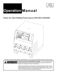
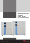
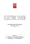
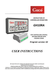
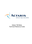
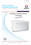
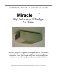
Installation, Operation and
Maintenance Manual
TX 250A
TX 500A
TX 750A
TX 1000A
Rev. 2014.10.01
Page 1 of 24
Turbovex A/S
Industrivej 45, DK – 9600 Aars
Telefon: +45 96 98 14 62 – Fax: +45 98 96 42 24
e-mail: [email protected] – www.turbovex.dk
1.0.0 Table of contents
1.0.0 TABLE OF CONTENTS ........................................................................................................................................ 2
2.0.0 ILLUSTRATIONS .................................................................................................................................................. 2
3.0.0 GENERAL INFORMATION ................................................................................................................................. 3
3.1.0 FOREWORD ........................................................................................................................................................ 3
3.2.0 FIELDS OF APPLICATION ................................................................................................................................ 3
3.3.0 MISUSE ................................................................................................................................................................ 3
3.4.0 CONTENTS OF DELIVERY ............................................................................................................................... 3
3.4.0 OPERATING PRINCIPLE ................................................................................................................................... 4
3.5.0 MAIN COMPONENTS: ....................................................................................................................................... 5
4.0.0 INSTALLATION ..................................................................................................................................................... 6
4.1.0 SCALE ILLUSTRATION..................................................................................................................................... 6
4.2.0 LOCATION .......................................................................................................................................................... 7
4.2.1 MINIMUM DISTANCE ....................................................................................................................................... 9
4.2.2 WALL- OR CEILING-MOUNTED UNIT ........................................................................................................... 9
4.3.0 INSTALLATION OF UNIT................................................................................................................................ 11
4.3.1 INSTALLATION WITH 2 DUCTS .................................................................................................................... 11
5.0.0 CONNECTION ...................................................................................................................................................... 16
5.1.0 WATER CONNECTION .................................................................................................................................... 16
5.1.1 FROST PROTECTION OF WATER HEATING COIL ..................................................................................... 16
5.2.0 POWER CONNECTION .................................................................................................................................... 18
5.3.0 POWER CONNECTION FOR ACCESSORIES ................................................................................................ 19
6.0.0 TECHNICAL SPECIFICATIONS ...................................................................................................................... 20
6.1.0 VENTILATION SYSTEM ................................................................................................................................. 20
7.0.0 OPERATION ......................................................................................................................................................... 21
7.1.0 REGULATION OF AIRFLOW .......................................................................................................................... 21
7.2.0 HEAT REGULATION........................................................................................................................................ 21
7.3.0 MASTER / SLAVE. ............................................................................................................................................ 21
8.0.0 SERVICE ............................................................................................................................................................... 22
8.1.0 CHANGE OF FILTER ........................................................................................................................................ 22
8.2.0 CLEANING OF EXCHANGER ......................................................................................................................... 23
9.0.0 DECLARATION OF CONFORMITY ................................................................................................................ 24
2.0.0 Illustrations
FIGURE 1 CONTENTS OF DELIVERY ............................................................................................................................. 3
FIGURE 2 MAIN COMPONENTS ...................................................................................................................................... 5
FIGURE 3 SCALE ILLUSTRATION................................................................................................................................... 6
FIGURE 4 LOCATION, CONVENTIONAL. ...................................................................................................................... 7
FIGURE 5 LOCATION IN A FALSE CEILING .................................................................................................................. 7
FIGURE 6 MINIMUM DISTANCE ..................................................................................................................................... 9
FIGURE 7 WALL-MOUNTED WITH WALL DUCTS………. ......................................................................... 10
FIGURE 8 CEILING-MOUNTED WITH CEILING DUCTS…. ....................................................................................... 10
FIGURE 9 LOCATION OF DUCTS................................................................................................................................... 10
FIGURE 10 MEASUREMENTS FOR MOUNTING THE SUSPENSION BRACKET OF A TX COMFORT UNIT ...... 11
FIGURE 11 WATER CONNECTION ................................................................................................................................ 16
FIGURE 12 CIRCUIT DIAGRAM ..................................................................................................................................... 18
FIGURE 13 CIRCUIT DIAGRAM FOR ACCESSORIES ................................................................................................. 18
Page 2 of 24
Turbovex A/S
Industrivej 45, DK – 9600 Aars
Telefon: +45 96 98 14 62 – Fax: +45 98 96 42 24
e-mail: [email protected] – www.turbovex.dk
3.0.0 General information
3.1.0 Introduction
This user manual contains technical information about installation, operation and
maintenance of the unit.
3.2.0 Fields of application
TX Comfort is designed for comfort ventilation in institutions, offices, dining spaces,
conference rooms and indoor spaces occupied by people.
3.3.0 Misuse
TX Comfort is designed for the living spaces described above in section 3.2.0. The system
is not designed for the purpose of local exhaust ventilation.
3.4.0 Contents of delivery
The TX Comfort unit is delivered with the following main components:
1. Turbovex TX Comfort unit
2. Suspension bracket
3. TX electronic controller
Figure 1 Contents of delivery
2.
1.
3.
Page 3 of 24
Turbovex A/S
Industrivej 45, DK – 9600 Aars
Telefon: +45 96 98 14 62 – Fax: +45 98 96 42 24
e-mail: [email protected] – www.turbovex.dk
3.4.0 Operating principle
Turbovex TX Comfort is a decentralized ventilation system with built-in heat recovery for
ventilation of comfort rooms in particular in indoor living spaces.
TX Comfort operates with an aluminium counter flow heat exchanger (5) to ensure
maximum heat recovery. The unit utilizes warm indoor air to heat up inflowing fresh
outdoor air. The counter flow heat exchanger’s sole function is for heat retention.
Airflow:
The air supply ventilator (6) (Figure 2) creates inflow of fresh outdoor air through the filter
(10), leading the inflow through the heat exchanger (5), and further through the air supply
grate (4) and out into the room.
At the same time the air exhaust ventilator (7) creates outflow of indoor air leading it
through the exhaust pipe (2) and further out to the open air outside.
The desired temperature of the air supply is regulated on the control panel. A sensor
records the actual temperature of the flowing air supply. If the temperature is lower than
the setpoint, the control system reduces the flow of the air supply warming it as it flows
through the heat exchanger.
Page 4 of 24
Turbovex A/S
Industrivej 45, DK – 9600 Aars
Telefon: +45 96 98 14 62 – Fax: +45 98 96 42 24
e-mail: [email protected] – www.turbovex.dk
3.5.0 Main components:
Figure 2 Main components
Page 5 of 24
Turbovex A/S
Industrivej 45, DK – 9600 Aars
Telefon: +45 96 98 14 62 – Fax: +45 98 96 42 24
e-mail: [email protected] – www.turbovex.dk
4.0.0 Installation
4.1.0 Scale illustration
Figure 3 Dimension Drawing
Dimension [mm]
TX 250A
TX 500A
TX 750A
TX 1000A
A
595.00
828.00
895.00
1050.00
B
403.00
493.00
565.00
665.00
C
500.00
710.00
766.00
917.00
D
313.00
382.00
442.00
542.00
E
1155.50
1505.50
1766.50
2066.50
F
1141.00
1491.00
1750.00
2050.00
G
1200.00
1550.00
1800.00
2100.00
H
906.00
1156.00
1355.00
1630.00
I
134.50
189.00
210.00
235.00
J
159.50
205.00
235.00
235.00
K
136.60
186.60
202.50
252.50
L
280,00
350,00
390,00
465,00
M
185,00
245,00
280,00
310,00
Page 6 of 24
Turbovex A/S
Industrivej 45, DK – 9600 Aars
Telefon: +45 96 98 14 62 – Fax: +45 98 96 42 24
e-mail: [email protected] – www.turbovex.dk
4.2.0 Location
The unit is generally placed on a wall directly under the ceiling. This location best exploits
the coanda effect as it leads the air further into the room along the surface of the ceiling. In
this way inflowing air can mix with the room’s existing air for a longer period of time and
thereby prevent draught. This location, as the point for supply and exhaust airflow,
provides optimal circulation within a room.
Figure 4 Location, conventional
The TX Comfort series also has the possibility of locating the unit in false ceilings. In this
way, the unit is less visible.
Figure 5 Location in a false ceiling
Page 7 of 24
Turbovex A/S
Industrivej 45, DK – 9600 Aars
Telefon: +45 96 98 14 62 – Fax: +45 98 96 42 24
e-mail: [email protected] – www.turbovex.dk
The TX Comfort series offer the possibility of installing ducts through the wall or the roof.
Fresh air can also flow in through a wall duct while exhaust air flows out through the roof.
This results in optimal conditions in comparison to a set up with close proximity between
the air supply and the air exhaust.
Page 8 of 24
Turbovex A/S
Industrivej 45, DK – 9600 Aars
Telefon: +45 96 98 14 62 – Fax: +45 98 96 42 24
e-mail: [email protected] – www.turbovex.dk
4.2.1 Minimum distance
Minimum allowed distance between the unit and walls, cupboards or other surfaces.
Figure 6 Minimum distance
Mål
TX 250A
TX 500A
TX 750A
TX 1000A
E
1155.50
1505.50
1766.50
2066.50
L
600.00
850.00
950.00
1100.00
It is important to check that there is sufficient space for the sides of the unit to be fully
opened during installation. The minimum distance must be the length L as indicated in the
illustration above.
4.2.2 Wall- or ceiling mounted unit
When the unit is wall- or ceiling mounted, the required outward free space from the centre
of each of the two ducts must be the distance M (see Figure 7 and 8.)
The location of the suspension bracket and the measurements for mounting the bracket
are indicated in the illustrations below.
Page 9 of 24
Turbovex A/S
Industrivej 45, DK – 9600 Aars
Telefon: +45 96 98 14 62 – Fax: +45 98 96 42 24
e-mail: [email protected] – www.turbovex.dk
Mål TX 250A
TX 500A
TX 750A
TX 1000A
M
142.00
192.00
209.00
259.00
N
906.00
1156.00
1355.00
1630.00
O
137.25
187.25
218.25
218.25
P
112.25
162.25
193.25
218.25
Q
136.60
186.60
202.50
252.50
Figure 7 Wall-mounted with wall ducts
Figure 8 Ceiling-mounted with ceiling ducts
The location of the unit in relation to the ducts (Please note that the unit is viewed from the
rear in the figure below).
Figure 9 Location of ducts
Page 10 of 24
Turbovex A/S
Industrivej 45, DK – 9600 Aars
Telefon: +45 96 98 14 62 – Fax: +45 98 96 42 24
e-mail: [email protected] – www.turbovex.dk
4.3.0 Installation of unit
4.3.1 Installation with 2 ducts
Install the suspension bracket on either the wall or the ceiling. Use the measurements to
pinpoint where to create the ducts and where to mount the bracket.
Mål
TX 250A
TX 500A
TX 750A
TX 1000A
MIN
13.00
13.00
15.00
15.00
M
129.00
178.50
194.00
243.00
1
88.50
138.50
168.00
192.50
2
994.50
1294.50
1523.00
1822.50
3
1108.00
1458.00
1716.00
2016.00
4
142.00
191.50
209.00
258.00
Figure 10 Measurements for mounting the suspension bracket of a TX Comfort unit
It is important that the ”MIN” measurement is followed carefully so that the unit has enough
space to be mounted on the bracket.
Page 11 of 24
Turbovex A/S
Industrivej 45, DK – 9600 Aars
Telefon: +45 96 98 14 62 – Fax: +45 98 96 42 24
e-mail: [email protected] – www.turbovex.dk
Drill two holes, 5 to 10 mm bigger than the ducts (R) through the wall or the ceiling. It is
important to observe all the minimum measurements described in section 4.2.1 Minimum
distance.
Mål
R
TX 250A
TX 500A
TX 750A TX 1000A
160.00
250.00
315.00
350.00
Page 12 of 24
Turbovex A/S
Industrivej 45, DK – 9600 Aars
Telefon: +45 96 98 14 62 – Fax: +45 98 96 42 24
e-mail: [email protected] – www.turbovex.dk
Loosen the two finger screws to open the doors on each side. Remove the suspension
bracket and mount it on the wall or the ceiling.
Suspension bracket
Finger screws
Place the unit on the bracket and mount it with the included 4 bolts.
Page 13 of 24
Turbovex A/S
Industrivej 45, DK – 9600 Aars
Telefon: +45 96 98 14 62 – Fax: +45 98 96 42 24
e-mail: [email protected] – www.turbovex.dk
Mount the ducts. If mounted on the facade, there must be a descending gradient of 1-2%
toward the outside to avoid penetration of heavy rainwater into the unit.
Mount the outside facade grates. Mount the grate of the air exhaust with the lamellas
facing sideways. The sideways direction should be oriented in the direction away from the
air supply. Mount the grate of the air supply with the lamellas facing downwards.
Note!
It is important to seal the ducts 100% at the spigot of the unit; otherwise
false air will penetrate the unit.
The ducts must on no account be twisted or pressed against the installation
collars of the unit, as it will cause an increased noise level of up to +6dB. Be
sure that the duct holes leave enough room for insulation with rockwool or
insulation foam.
Connect the power supply according to the included electrical diagram.
Page 14 of 24
Turbovex A/S
Industrivej 45, DK – 9600 Aars
Telefon: +45 96 98 14 62 – Fax: +45 98 96 42 24
e-mail: [email protected] – www.turbovex.dk
Note!
The power connection must be performed by a professional electrician.
There are two different approaches of locating the main circuit board.
1. Open the left hand side of the unit and remove the service hatch.
2. Remove the front panel.
The front panel can be removed by loosening the set screws with an Allen key.
The main circuit board will be found in the left side of the unit. See figure 2 page 5.
Set screw
Mount the front panel and/or sides and the unit is ready for use. Make sure to tighten the
set screws, otherwise leakage may occur in the unit.
Page 15 of 24
Turbovex A/S
Industrivej 45, DK – 9600 Aars
Telefon: +45 96 98 14 62 – Fax: +45 98 96 42 24
e-mail: [email protected] – www.turbovex.dk
5.0.0 Connection
5.1.0 Water connection
Refer to Section 5.1.1 before connecting the water.
It is recommended to use a Danfoss FV filter on the inlet to the unit to prevent blockage of
the water heater.
NB! The connections are made to the unit fixed connections, see Fig. 11
Figur 11 Water connection
Water connection 3/8"
Outlet
Inlet
5.1.1 Frost protection of water heating coil
To ensure safe frost protection of water heating coil with the built and factory-tested
automatic, the heating coil must always be connected to central heating systems with:
•
•
Flow temperature which is never below + 40°C when freezing weather.
Water flow in heating coil which is never less than 20 liters. hour at flow
temperature of +40°C when freezing weather.
The radiator thermostat inside the unit is, as antifreeze, locked to an air temperature of
approx. 14°C. This causes the radiator thermostat opens if the air temperature drops
below 14°C, ensuring water flow through the heating coil, when the system is in standby. If
you change this setting, there is a risk that the heating coil can cause frost damage.
Page 16 of 24
Turbovex A/S
Industrivej 45, DK – 9600 Aars
Telefon: +45 96 98 14 62 – Fax: +45 98 96 42 24
e-mail: [email protected] – www.turbovex.dk
Warning for frost protection of water heaters
Water heating coil should never be connected to central heating systems, which closed for
heat supply - eg. in weekend and holiday periods, so the flow temperature falls below
+40°C by freezing weather.
If the flow temperature is below +40°C there is a risk of frost damage on the heating coil,
because the heating coil is placed in the inlet from the outdoor air, where the heating coil
(along with air to air heat exchanger) during normal operation, heat the clean outdoor air
for comfort temperature.
Water heating coil should never be connected to central heating systems where the water
flow through the heating coil is interrupted – i.e. central heating systems with circulation
pump is stopped or switched on for low pump pressure at night setting.
Please also refer to the label that is affixed to the unit:
Important !
Connection to units with water heating.
The heating element is secured against bursting from frost,
down to -12 °C, when the value at the scale of the
thermostate is set to min. "1,5"
The difference pressure must be at least 0.3 bar and max.
0.9 bar, wich can be secured by adding a regulator in the
systems main circuit
If the difference pressure is less than 0.3 bar, it will infer
on the closing speed of the servo valve.
Page 17 of 24
Turbovex A/S
Industrivej 45, DK – 9600 Aars
Telefon: +45 96 98 14 62 – Fax: +45 98 96 42 24
e-mail: [email protected] – www.turbovex.dk
5.2.0 Power connection
Connection of Turbovex TX Comfort according to the circuit diagram, see Fig. 12
Note!
The power connection must be performed by a professional electrician.
.
Figure 12 Circuit diagram
Note!
A circuit breaker must be installed in front of the ventilation system.
Page 18 of 24
Turbovex A/S
Industrivej 45, DK – 9600 Aars
Telefon: +45 96 98 14 62 – Fax: +45 98 96 42 24
e-mail: [email protected] – www.turbovex.dk
5.3.0 Power connection for accessories
Connection of Turbovex TX Comfort according to the circuit diagram, see Fig. 13
Note!
The power connection must be performed by a professional electrician.
.
Figure 13 Circuit diagram for accessories
Page 19 of 24
Turbovex A/S
Industrivej 45, DK – 9600 Aars
Telefon: +45 96 98 14 62 – Fax: +45 98 96 42 24
e-mail: [email protected] – www.turbovex.dk
6.0.0 Technical specifications
6.1.0 Ventilation system
Unit:
TX 250A
TX 500A
TX 750A
TX 1000A
Unit
1200
1550
595
403
828
493
1800
2100
895
565
1050
665
mm
mm
mm
2 x 160
2 x 250
2 x 315
2 x 315
mm
Weight:
32
41
80
95
Kg
Capacity:
Min
Max
Forced
100
250
480
300
500
800
350
750
1100
500
1000
1600
m³/h
m³/h
m³/h
Sound:
Min
Max
Forced
26
35
50
25
35
53
25
35
50
27
35
48
dB(A)
dB(A)
dB(A)
Filter:
F5
F5
F5
F5
Filter class
Min
12,6
454
9,8
118
28,5
293
14
101
Watts
J/m³
Max
28
403
65
468
78
374
150
540
Watts
J/m³
Forced
110
825
113,6
511
185
605
199
448
Watts
J/m³
Output (motor):
2 x 71
2 x 90
2 x 170
2 x 175
Watts
Power supply:
1 x 230/50
1 x 230/50
1 x 230/50
1 x 230/50
Volt/Hz
80,6
84,5
78
80,6
%
400
650
1000
1250
Watt
340
670
1260
1340
Watt
Dimension:
S
Length
Depth
Height
Duct:
Energy consumption (motor):
Temperature efficiency:
Electric heating surface
(option):
Water heating surface
(option):
Air flow indicates the balanced air renewal in relation to the motor voltage and is stated as m3/h.
Contact the distributor if the unit is to be used with forced operation.
The sound level is indicated in decibels (dB) in relation to the air renewal, measured at a distance
of 1 meter in front of and 1 meter directly below the air supply grate. By way of comparison it may
be mentioned that whispering corresponds to 30 dBA, ordinary spoken conversation corresponds
to 60 dB and street traffic to about 90 dBA.
The temperature efficiency on the exchanger is indicated as a percentage (%) and is expressed as
the ratio between the obtained temperature difference and the maximum achievable temperature
difference.
Page 20 of 24
Turbovex A/S
Industrivej 45, DK – 9600 Aars
Telefon: +45 96 98 14 62 – Fax: +45 98 96 42 24
e-mail: [email protected] – www.turbovex.dk
7.0.0 OPERATION
7.1.0 Regulation of airflow
See also the included manual for the TX electronic controller.
The unit has 2 operational settings. Operation by day provides the dimensioned volume of
air the unit was installed for. Operation by night runs slower to save energy during night
time.
Note! By regulating the volume of air with a CO2 sensor, the unit controls the velocity
required for the room.
Note!
The after-run period of ventilation systems with an electric postheating
surface is approximately 80 seconds.
7.2.0 Heat regulation
See also the included manual for the TX electronic controller.
The desired temperature is regulated using the control panel. The temperature should not
be set higher than the room temperature. The temperature of the fresh air should be 2-3
degrees below the room temperature to provide optimal circulation within the room.
When the unit shuts down, it automatically saves the latest temperature setting and will
use this setting when it starts up again.
The unit has a fully automated by-pass system that leads the air around the exchanger
when the temperature allows it.
7.3.0 Master / slave
This function requires a small circuit board that can be acquired at the distributor.
Up to 5 slaves can be connected to a master. One unit can thus control 5 other units, so
that all 6 units run in exactly the same way.
See the user manual for master/slave options and how to correctly set up the units.
As a standard, the unit is a master.
Page 21 of 24
Turbovex A/S
Industrivej 45, DK – 9600 Aars
Telefon: +45 96 98 14 62 – Fax: +45 98 96 42 24
e-mail: [email protected] – www.turbovex.dk
8.0.0 Service
8.1.0 Change of filter
It is recommended to change the filters 2-4 times
per year.
1. Change of supply air filter.
•
Loosen the set screws and open the front
Cover using an Allen key.
•
Open the front Cover
•
Loosen the 2 thumbscrews and tilt the filter
holder.
•
Replace the used filter with a new one.
The side marked “Dust Air Side” must
be facing your direction.
•
Tighten the thumb screws, securing the
filter holder.
2. Change the exhaust filter
•
Remove the exhaust air filter out and
replace it with a new one.
•
Close the front Cover.
•
Make sure to tighten the set screws in
order to avoid any leakage in the unit.
Page 22 of 24
Turbovex A/S
Industrivej 45, DK – 9600 Aars
Telefon: +45 96 98 14 62 – Fax: +45 98 96 42 24
e-mail: [email protected] – www.turbovex.dk
8.2.0 Cleaning of heat exchanger
It is recommended to clean the heat exchanger once a year.
Note!
Shut off the supply voltage before opening
the front Cover.
• Loosen the set screws using an Allen key and open the front Cover.
Set screws
• Remove the cover and pull out the heat exchanger. Gently clean the heat exchanger
using a vacuum cleaner.
Cover
• Reinsert the heat exchanger and mount the cover.
• If necessary replace the exhaust filter
Heat exchanger
• Close the front Cover.
Make sure to tighten the set screws to avoid
any leakage in the unit.
Page 23 of 24
Turbovex A/S
Industrivej 45, DK – 9600 Aars
Telefon: +45 96 98 14 62 – Fax: +45 98 96 42 24
e-mail: [email protected] – www.turbovex.dk
9.0.0 Declaration of conformity
Page 24 of 24
Turbovex A/S
Industrivej 45, DK – 9600 Aars
Telefon: +45 96 98 14 62 – Fax: +45 98 96 42 24
e-mail: [email protected] – www.turbovex.dk