1
T3 Series
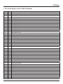
1.7.2 List of registers in the T3-8AIAO
Note: When using the Modbus Poll software, addressing should be set to “Protocol Addresses (Base 0)” under the
“Display” menu.
Address
Bytes
0 to 3
4
Serial Number, 4 byte value
Register and Description
4
1
EEPROM hardware Version Number
5
1
Firmware Version Number
6
1
ADDRESS. Modbus device address
7
1
Product Model
8
1
Hardware Revision
9
1
PIC Version Number
13
1
Calibration register – used to calibrate the outputs.
15
1
Baudrate setting: 0 will set 9600bps, 1 will set 19200bps
100
2
Output 1 Register
101
2
Output 2 Register
102
2
Output 3 Register
103
2
Output 4 Register
104
2
Output 5 Register
105
2
Output 6 Register
106
2
Output 7 Register
107
2
Output 8 Register
108
2
Input 1 Register
109
2
Input 2 Register
110
2
Input 3 Register
111
2
Input 4 Register
112
2
Input 5 Register
113
2
Input 6 Register
114
2
Input 7 Register
115
2
Input 8 Register
116
2
117
2
118
2
Register 116 , 117 and 118 hold the position information on each of the hand-off-auto switches on the T3 modules
Each switch has three positions and therefore each switch requires 2 bits to hold the state.
Modbus registers are 16 bits wide so we can hold the status of 8 switches in register 116, the next 8 are held in register 117
and so on, up to the number of switches on the particular T3 module.
The switch states are as follows:
00= off , the switch is in the center position
10=auto, the switch is positioned towards the terminal block
01= hand, manually on. The switch is positioned towards the center of the module (away from the terminal block).
119 - 125
1
Range for each input, 118 correspond to ch1.0 = raw data,1 = 10K Celsius, 2 = 10K Fahrenheit ,3 = 0 - 100%,4 = ON/OFF, 5
= OFF/ON
126-133
1
Filter coefficient for input 1 to 8,value is 0 through 100,default is 20.
Example: register 118 reads 5 (hex 05)
register 119 reads 138 (hex 8A)
The Pulse Count for Channel1 is then 1418 pulse (hex 058A)
Writing to register 134 will clear registers 118 and 119. Subsequent registers 135 to 138 are optional memory to
store date and time at which Pulse Counts have been cleared.
-6-