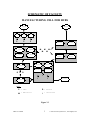
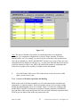
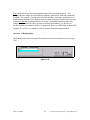
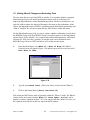
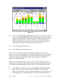
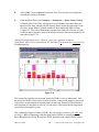
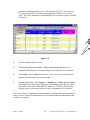
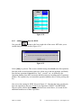
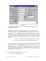
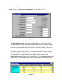
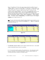
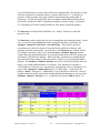
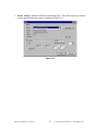
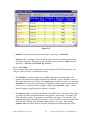
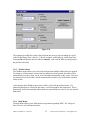
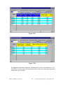
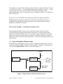
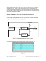
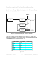
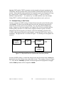
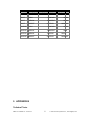
1
MPX WIN 4.3 For use with Windows User Manual Network Dynamics, Incorporated 10 Speen Street Framingham, MA 01701, USA Tel: (508) 879-9200 Fax: (508) 879-9201 E-mail: [email protected] Website: www.networkdyn.com Copyright © 2003 Network Dynamics Inc. All Rights Reserved. First Edition printed 1999. Printed in the United States. The contents of this manual are subject to change without notice. MPX is a registered trademark of Network Dynamics, Incorporated. Microsoft Windows, Access, Excel, and NT are registered trademarks of Microsoft Corporation. TABLE OF CONTENTS OVERVIEW OF MPX RELEASE WIN 4.3 ...........................….............vi PREFACE...................................................................................................viii 1 INSTALLATION....................................................................................... 1 1.1 HARDWARE AND SOFTWARE REQUIREMENTS....................................................................... 1 1.2 INSTALLATION INSTRUCTIONS............................................................................................ 1 1.3 INSTALLATION PROCESS................................................................................................... 2 2 HOW TO USE THIS MANUAL.............................................................. 1 3 A QUICK TOUR OF MPX....................................................................... 1 3.1 THE MANUFACTURING SYSTEM AND PRODUCTS.................................................................. 1 3.2 THE MPX MODEL OF THE MANUFACTURING SYSTEM......................................................... 4 3.2.1 Starting the Program.......................................................................................... 4 3.2.2 Saving the Model in a New File......................................................................... 9 3.2.3 Model Title and General Data......................................................................... 10 3.2.4 Labor Data....................................................................................................... 12 3.2.5 Equipment Data................................................................................................ 15 3.2.6 Overview of Hub Assembly...............................................................................18 3.2.7 Product Data.................................................................................................... 19 3.2.8 Overview of Product Operations and Routing................................................. 21 3.2.9 Operations/Routing Data................................................................................. 24 3.2.10 Indented Bill of Materials (IBOM) Data........................................................ 30 3.3 RUNNING THE MODEL................................................................................................... 36 3.4 LOOKING FOR A POSSIBLE SOLUTION............................................................................... 39 3.5 MAKING WHAT-IF CHANGES AND EVALUATING THEM....................................................... 42 3.6 USING MPX TO REDUCE THE LEAD TIME IN THE MANUFACTURING CELL........................... 47 3.6.1 The Current Lead Time.................................................................................... 48 3.6.2 First What-if: Larger Lot Sizes for HUB1.......................................................49 3.6.3 Second What-if: Cut All Lot Sizes by About a Half......................................... 51 3.6.4 Third What-if: Setup Reduction Project.......................................................... 53 3.6.5 Viewing the What-if Changes........................................................................... 55 3.6.6 Challenge Yourself........................................................................................... 55 3.7 ENDING THE TUTORIAL SESSION..................................................................................... 55 3.8 PREVIEW OF NEXT STEPS............................................................................................... 56 4 BUILDING A NEW MODEL................................................................... 1 4.1 STEPS BEFORE STARTING THE MODELING.......................................................................... 1 4.2 THE MANUFACTURING SYSTEM AND PRODUCTS.................................................................. 2 MPX User Manual for Version 4.3 ii 2003 Network Dynamics Inc., Framingham, MA 4.3 STARTING THE PROGRAM................................................................................................. 7 4.4 ENTERING THE GENERAL DATA........................................................................................ 8 4.5 ENTERING LABOR DATA.................................................................................................. 9 4.5.1 Data Input Using a Form................................................................................... 9 4.5.2 Using the Table Format to Copy Data............................................................. 10 4.6 SAVING YOUR WORK................................................................................................... 13 4.7 ENTERING EQUIPMENT DATA..........................................................................................14 4.7.1 Adding New Rows in the Table Format............................................................14 4.7.2 Correcting Data Entry Errors.......................................................................... 15 4.7.3 Entering the Remaining Equipment Data........................................................ 15 4.8 ENTERING PRODUCT AND OPERATIONS DATA....................................................................17 4.8.1 Beginning with Two Products.......................................................................... 17 4.8.2 Adding Operations Data for HUB1..................................................................17 4.8.3 Adding Routing Data for HUB1....................................................................... 19 4.8.4 Filling in the Setup and Run Time Data for HUB1.......................................... 21 4.8.5 Adding the Data for BOLT............................................................................... 22 4.8.6 Copying Product Data......................................................................................23 4.9 ENTERING IBOM DATA............................................................................................... 27 4.9.1 Building a New IBOM...................................................................................... 27 4.9.2 Copying IBOM Data........................................................................................ 29 4.10 NEXT STEPS...............................................................................................................30 5 ADVANCED FEATURES IN MPX 4.3................................................... 1 5.1 ADVANCED DATA ON INPUT SCREENS................................................................................1 5.1.1 General Input Data............................................................................................ 2 5.1.2 Labor Input Data................................................................................................ 4 5.1.3 Equipment Input Data........................................................................................ 6 5.1.4 Product Input Data........................................................................................... 10 5.1.5 Operations/Routing Input Data........................................................................ 16 5.1.6 All Operations Input Data................................................................................ 21 5.1.7 Aggregation Products to one Part....................................................................24 5.2 MPX UTILITY FUNCTIONS ........................................................................................... 26 5.2.1 File Menu......................................................................................................... 26 5.2.2 Edit Menu......................................................................................................... 29 5.2.3 View Menu........................................................................................................ 31 5.2.4 Records Menu................................................................................................... 34 5.2.5 Window Menu................................................................................................... 35 5.2.6 Help Menu........................................................................................................ 35 5.3 ADDITIONAL FEATURES IN RUN MENU............................................................................ 37 5.3.1 Product Inclusion............................................................................................. 37 5.3.2 Max. Throughput + Lot size range................................................................... 38 5.3.3 Optimize Lot Sizes and Transfer Batches......................................................... 39 39 5.4 ADVANCED OUTPUT CHARTS AND TABLES....................................................................... 41 5.4.1 Output Summary............................................................................................... 41 5.4.2 Labor Outputs...................................................................................................42 MPX User Manual for Version 4.3 iii 2003 Network Dynamics Inc., Framingham, MA 5.4.3 Equipment Outputs........................................................................................... 46 5.4.4 Product Outputs............................................................................................... 49 5.4.5 IBOM Outputs.................................................................................................. 53 5.5 ADDITIONAL OPTIONS IN WHAT-IFS ................................................................................ 57 5.5.1 What-if Display.................................................................................................57 5.5.2 What-if Records................................................................................................ 57 5.5.3 What-if Families............................................................................................... 58 5.5.3.1 Creating a What-if family............................................................................ 60 5.5.3.2 Naming What-ifs within a Family............................................................... 61 5.5.3.3 Viewing all the What-if Family Data.......................................................... 62 5.5.3.4 Other What-if Family Utilities.................................................................... 63 5.5.3.5 Editing What-if Family membership........................................................... 63 6 PREMISES OF THE MPX ANALYSIS: WHAT EVERY USER SHOULD KNOW ......................................................................................... 1 6.1 BASIC PREMISES OF RAPID MODELING TECHNOLOGY........................................................... 1 6.1.1 Static and Dynamic Models................................................................................ 1 6.1.2 Steady State Averages........................................................................................ 2 6.1.3 First Come, First Served.................................................................................... 3 6.1.4 Buffer Space and Blocking................................................................................. 4 6.1.5 Definition of Discrete Part Manufacturing........................................................ 4 6.1.6 Accuracy and Sensitivity Analysis...................................................................... 4 6.1.7 When MPX is Not Appropriate........................................................................... 6 6.2 THEORY BEHIND THE MPX ANALYSIS.............................................................................. 7 6.3 PREMISES OF THE MAIN “BUILDING BLOCKS” IN MPX....................................................... 8 6.3.1 How MPX Models Statistical Variability........................................................... 8 6.3.2 Definition of Lot and Transfer Batch............................................................... 11 6.3.3 How MPX Models Equipment Operation......................................................... 12 6.3.4 Equipment Breakdowns.................................................................................... 13 6.3.5 Equipment Overtime (and Effect on Flow Time)..............................................15 6.3.6 How MPX Models Labor.................................................................................. 16 6.3.7 How MPX Models Overtime for Labor ........................................................... 19 6.3.8 Effect of Equipment and Labor Setup/Run Factors..........................................20 6.3.9 How MPX Models Product Flow Time............................................................ 21 6.3.10 How MPX Handles Scrap...............................................................................23 7 EXPERT MODELING TECHNIQUES ................................................. 1 7.1 EXTENDING MPX.......................................................................................................... 1 7.2 THE DELAY STATION CONCEPT........................................................................................ 2 7.3 TYPES OF FEEDBACK (REWORK) LOOPS............................................................................. 7 7.4 MULTIPLE ENTRY OR EXIT POINTS.................................................................................. 10 7.5 LOT SIZE CHANGES...................................................................................................... 11 7.6 COMBINING OR RE-INTERPRETING BUILDING BLOCKS......................................................... 17 7.6.1 Continuous Feed Processes..............................................................................17 7.6.2 Multiple Lot Operations................................................................................... 20 MPX User Manual for Version 4.3 iv 2003 Network Dynamics Inc., Framingham, MA 7.6.3 Scheduled Maintenance.................................................................................... 21 7.7 USEFUL TESTS FOR YOUR EXTENSIONS OF MPX .............................................................. 21 8 APPENDIX A............................................................................................. 1 9 APPENDIX B............................................................................................. 8 10 INDEX..................................................................................................... 11 11 GLOSSARY............................................................................................ 18 12 MPX QUICK REFERENCE.................................................................. 1 MPX User Manual for Version 4.3 v 2003 Network Dynamics Inc., Framingham, MA OVERVIEW OF MPX RELEASE Win 4.3 MPX Win 4.3 has all the features that made previous releases popular: • Rapid modeling engine that evaluates the dynamics and interactions of the manufacturing system yet is lightning fast in computing results. • Models multiple products (each with its own routing, lot size, setup and run times), along with complex bill-of-material structures. • Both equipment and labor constraints are modeled, as well as the effect of dynamic labor-machine interaction (also known as “operator interference”). • Models many “real-world” manufacturing details such as effects of equipment failures, scrap, and rework loops. Includes convenient “what-if dials” to model improvements such as setup reduction. • Outputs include production levels, work-in-process (WIP) and actual lead times. • Uses less disk space through more frequent data compression. • Consistent handling of operations with the same name. User warned when multiple operations with the same name. • Printing and export features for all graphs / charts. • Recalc All button on the what-if display screen to allow user to recalculate all whatifs without reloading each one. • Automatically loads Equipment and Labor results screens when production is not achieved. • Keeps data screens open when running calculations or changing what-ifs. • Allows equations for setup/run times and routing probabilities—these quantities can depend on parameters specific to a product, or labor, or equipment item. • Setup and run operation times can be specified per lot, per transfer batch and per piece, as well as run time per lot, per transfer batch and per piece (earlier versions of MPX only allowed setup time per lot and run time per piece). • Several Run options, including: Products included for the current Run; Find the maximum production achievable and Run a range of lot sizes. • Reports include a Bill-of-Materials Tree Chart that displays the lead time for an assembly built up through the lead times of all its subassemblies and components. Plus a Pole Chart, which shows all possible paths from initial components to final assembly, sorted by lead time, to highlight the critical path components. (In addition, user can specify each part as make-to-stock or make-to-order.) • Can simultaneously display results for any number of What-if scenarios. • Office 2000, XP compatible. MPX User Manual for Version 4.3 vi 2003 Network Dynamics Inc., Framingham, MA • Windows 2000, Me, XP compatible. • New Installation procedure – to eliminate operating system lockups. • Dialog box to orient the user when opening MPX. • Equipment can be designated as “out of area” for improved interpretation of output graphs. • Department codes have been added to Labor, Equipment, and Product input screens to help segregate products. Output data are subtotaled according to the Product department codes. • Editing of What-if and basecase data directly in the what-if records screen. • Advanced sorting capabilities for all input/output tables. • Operation details output tables include additional descriptions for each data column. • Font selection. • Lot Size Factor. • Labor prioritize. • Aggregation. • Display operations for all products. • Summary result table rotation. • Help linked to all screens. Plus, New in Release Win 4.3: The major changes are: • Choosing user level (see section 3.2.1). • Units per final assembly. • Optimize lot sizes and transfer batches (see section 5.3.3). • What-if families (see section 5.5.3). • Input and output tables can be sorted in the order or sequence they were entered. • Reports for error messages, parameter names and what-ifs. • Convert to version 4.2 or earlier (see section 5.2.1). PREFACE MPX Supports Quick Response and Continuous Improvement MPX User Manual for Version 4.3 vii 2003 Network Dynamics Inc., Framingham, MA Successful manufacturing in the 21st century will belong to enterprises that can respond quickly to their customers’ specific needs. Implementing such quick response—and then remaining ahead of the competition—will require companies to continuously examine ways to reduce their lead times. MPX® is an easy-to-use software tool to assist companies in achieving and sustaining quick response in their manufacturing operations. In addition, MPX can assist engineers and managers analyze their operations to find opportunities for improvements related to capacity, work-in-process, labor allocation, new product introduction and many other manufacturing issues. MPX is designed for swift and frequent decision making. The software requires no programming or any other special knowledge of computer languages. MPX enables decision-makers to quickly answer questions such as: • How can we cut lead times for sheet metal components from 8 weeks to 3 weeks? Would reducing setups on the press brake help? If so, by how much should the setups be reduced? • How does our current lot sizes impact our lead times? Should our lot sizes be smaller or larger? • Can we sustain our short lead times with the recent increase in demand, or do we need to increase capacity to sustain our current response time? • Will 2 operators be sufficient to tend the group of 5 semi-automated milling machines? What will be the impact on lead time and production capacity if we cross-train the mill operators and lathe operators? Based on Rapid Modeling Technology Embedded within MPX is a powerful methodology, called Rapid Modeling Technology (RMT). RMT is based on the established technique of queuing theory, a branch of engineering applied mathematics that describes factory floor dynamics particularly well. The key issue here is that a factory’s lead times, work-in-process, and actual capacity are all the result of complex dynamics and interactions on the manufacturing shop floor. For instance, lead time depends on both processing time and queue time (this is the time parts spend waiting to get their turn at machines, when the machines are busy). While processing time may be known based on the machining parameters, queue time depends on many “dynamic” factors such as, which other parts are already in queue to use the machine, whether the machine has broken down, whether an operator is available, and so on. In order to predict whether a decision will improve lead times, it is thus necessary to be able to predict these queue times, which means any lead time reduction tool must model these dynamics and interactions. The RMT technology in MPX models these complex dynamics of the manufacturing facility in terms of mathematical equations. Until a few years ago, these equations couldn’t be solved. However, with the progress that has been made in queuing theory in MPX User Manual for Version 4.3 viii 2003 Network Dynamics Inc., Framingham, MA recent years, very good estimates can now be obtained for system performance with amazingly little computer time, often just seconds on a personal computer. The complexity of the equations means that specialized software must be written so that decision makers don't have to deal with the underlying technical complexities. Network Dynamics Inc. (NDI) has developed RMT into a powerful software tool that fits the needs of industry users. MPX Release Win 4.3 is the latest result of our efforts on this front. Advantages Over Other Methods Prior to RMT-based tools such as MPX, there were no easy-to-use methods to model and evaluate manufacturing systems quickly, efficiently and accurately. But there were other methods being used: Electronic spreadsheets such as Excel are simple and easy to use, but calculations are typically based on static models, which don't take into account the dynamics of the manufacturing environment, such as interactions between products, setups, machine failures and rework. All these factors impact lead times, work-in-process, and capacity. MRP systems can perform rough capacity planning. Indeed, MRP serves as a good database for bill-of-materials, and as a “backward explosion” from delivery dates to obtain start dates for assemblies, re-ordering, etc. But MRP systems are usually large and unwieldy, requiring long run times, and they cannot easily model hypothetical facilities (such as those contemplated for a new product line, whose data do not already exist in the MRP database). Most important, the MRP system cannot assist with evaluating alternatives for lead time reduction, since lead time is given as a fixed input to the MRP system, rather than an output that varies with actual load and other interactions, as it should be! Detailed (Discrete-event) Simulation is perhaps the most sophisticated and complex of all the software tools used for manufacturing systems modeling today. Discrete-event Simulation mimics the operations of the factory floor, literally step by step. For all its sophistication, and perhaps because of it, simulation requires trained analysts with thorough knowledge of the complex software, and experience on how to interpret the mathematical statistics that are the principal output of simulation. Models can take a long time to build and debug, and changes to the simulation model are onerous and time consuming. Most discouragingly, simulation is computation-intensive and very slow: the time required to run each “what-if” scenario could extend to hours on a PC. Thus simulation lacks the immediacy and responsiveness that is so appealing with MPX. MPX provides just the right balance between too little detail (~spreadsheets), and too much (~simulation). In keeping with the effective management approach of “80/20 analysis,” or forest first, trees later, MPX helps decision-makers rapidly home-in on the key decisions that significantly impact lead time, work-in-process and capacity. And it does all this swiftly and easily. Building a Shared Vision: Using MPX Across Functional Lines MPX User Manual for Version 4.3 ix 2003 Network Dynamics Inc., Framingham, MA MPX isn’t just for technical analysts or manufacturing managers. Manufacturing improvement teams find MPX a useful communication tool across the organization. The reason is, MPX is easy to understand by everyone in the company, and thanks to MPX’s speed, you can conduct “live” what-ifs during meetings, to arrive at a group consensus. MPX has helped product introduction teams understand the impact of many fabrication and assembly process alternatives. It has enabled analysts to better justify capital equipment requests, not just for capacity reasons, but also by linking the request to specific lead time objectives. MPX helps Sales/Marketing develop more accurate and reliable quotes on delivery time. MPX has often been used to “sell” shop floor workers on the need for setup and lot size reductions. In these ways, MPX helps bring the disparate functions in the company together to develop a shared vision, not by stating dogmatic principles, but rather, by providing quantitative tradeoffs to understand the alternatives being considered. MPX Makes It Fun to Compete! You will find that MPX is fun to use. The software is entirely menu-driven, within an intuitive, window environment. All you do is plug in the production parameters, all the time being guided by the pull-down screens, status lines and instructions. MPX does the rest, from checking your data entry to generating a full bevy of performance reports and graphs. Once you are satisfied with a baseline model of your facility, you can easily explore any number of process alternatives through MPX’s powerful What-If query tools, and see the implications automatically ripple through to new performance results in a matter of seconds. Truly, MPX assists you in achieving a sustainable manufacturing competitive advantage through a process of continuous improvement. MPX User Manual for Version 4.3 x 2003 Network Dynamics Inc., Framingham, MA 1 Installation This chapter will lead you through the steps needed to install the MPX Rapid Modeling Software on your computer. The installation of MPX is simple and should take you less than five minutes. Installation of the newest version of MPX will not remove any earlier versions of MPX already on your machine. 1.1 Hardware and Software Requirements In order to install and use MPX, you need the following minimum hardware and software on your computer: Processor: 486 class or higher. Any Color Monitor: VGA, SVGA. Operating System: Windows 95, 98, Me, 2000, NT or XP. RAM Memory: At least 16Mb for Windows 95, 98 or Me. At least 32Mb for Windows NT, 2000 or XP. Hard Drive: Minimum 50Mb free space. Accessories: Mouse (Microsoft-compatible), CD-ROM (for installation only). 1.2 Installation Instructions 1) Start Windows. (If Windows is already running, close all existing applications.) 2) Insert the “MPX CD-ROM” in the CD-ROM drive. 3) Click on the Start button in the lower left corner and select Run…. 4) We’ll assume your CD-ROM drive is labeled “D”. In this case, type d:\setup and press Enter. (Otherwise, replace “d” by the letter for your CD-ROM drive in the above line.) NOTE: Alternatively, you can locate the file setup.exe on the CD-ROM and double click on it to start the installation process. MPX User Manual for Version 4.3 1 2003 Network Dynamics Inc., Framingham, MA 1.3 Installation Process The installation process will start after step 4 above. You will be prompted for a minimal amount of information during the installation process. The input screens, recommended responses and an explanation of your options are listed below. Screen 1: If it was the first time that you install MPX on the computer, you may get the following message. (Otherwise, you will go to screen 2.) Explanation of Options: 1) OK – Start installation of MDAC (recommended response). 2) Cancel - Exit installation process (software will not be installed). Click OK, you will get the following message: MPX User Manual for Version 4.3 2 2003 Network Dynamics Inc., Framingham, MA Screen 2: Explanation of Options: 1) Next – Start installation process (recommended response). 2) Cancel - Exit installation process (software will not be installed). MPX User Manual for Version 4.3 3 2003 Network Dynamics Inc., Framingham, MA Screen 3: Explanation of Options: 1) Accept – Accept User’s Agreement, continue installation process 2) Decline – Decline User’s Agreement, exit installation process MPX User Manual for Version 4.3 4 2003 Network Dynamics Inc., Framingham, MA Screen 4: Explanation of Options: 1) Back – Return to the previous screen 2) Next – Continue installation process (recommended response). 3) Cancel - Exit installation process (software will not be installed). 4) Browse – Click to change the disk and/or directory where MPX will be installed. (Default directory for installation is C:\Program Files\MPX_43) MPX User Manual for Version 4.3 5 2003 Network Dynamics Inc., Framingham, MA Screen 5: Explanation of Options: 1) Back – Return to the previous screen 2) Next – Continue installation process (recommended response). 3) Cancel - Exit installation process (software will not be installed). 4) You can change the name of the folder where the MPX icon will be placed in the Programs submenu under the windows Start Button MPX User Manual for Version 4.3 6 2003 Network Dynamics Inc., Framingham, MA Screen 6: Explanation of Options: 1) Back – Return to the previous screen 2) Next – Continue installation process (recommended response). 3) Cancel - Exit installation process (software will not be installed). MPX User Manual for Version 4.3 7 2003 Network Dynamics Inc., Framingham, MA Screen 7: Explanation of Options: 1) You must enter the Serial Number given to you by Network Dynamics, Inc. (located on the front of the MPX CD case) in the Password field and click OK in order to proceed. MPX User Manual for Version 4.3 8 2003 Network Dynamics Inc., Framingham, MA Screen 8: Explanation of Options: This screen shows progress of the installation, and is for user information only. MPX User Manual for Version 4.3 9 2003 Network Dynamics Inc., Framingham, MA Screen 9: Explanation of Options: 1) Finish - Exit installation process. MPX User Manual for Version 4.3 10 2003 Network Dynamics Inc., Framingham, MA Screen 10: If a MPX-related component is in use and needs to be updated you will get a message such as the following: Explanation of Options: 1) OK – Causes the system to restart immediately (recommended response). 2) Cancel – exits the setup program and returns to Windows (Warning: MPX will not work correctly until the system is restarted). MPX User Manual for Version 4.3 11 2003 Network Dynamics Inc., Framingham, MA 2 How to Use this Manual This User Manual is written to accompany MPX Win 4.3. Please note the following points: • This Manual focuses on key points that quickly enable you to begin using MPX. • Although the structure of MPX models and data is almost the same as in previous versions, there are many new capabilities, and several new features in the interface. For the fastest learning experience, it is suggested that you work through the five chapters in sequence, namely: 1. Installation. 2. How to Use this Manual. 3. A Quick Tour of MPX. 4. Building a New Model. 5. Advanced Features in MPX Win 4.3. • After completing these five chapters, you should be ready to use all the capabilities of MPX Win 4.3 to the fullest extent. • Information on these features is available in the help menu within this version of MPX. • To quickly find information on specific MPX functionality, use the MPX Quick Reference, found in Chapter 12. The layout of the quick reference directly matches the structure of the MPX file menus, which makes finding information on specific MPX functions quick and easy. • Please keep track of problems that you have and communicate these to NDI. This will help to increase the quality of the software. In your MPX file directory, you will find a template for reporting software issues to NDI (MPX_Software_Issues_Form.doc). Please fill out the form and send it via e-mail to [email protected] (also attach any other related files, e.g. *.mdb). It will be reviewed and properly handled. NDI will get back to you within one week. After you have mastered the basic use of MPX it is worthwhile to return and read the last two chapters: 6. Premises of the MPX Analysis: What Every User Should Know. 7. Expert Modeling Techniques. Thank you for your interest in using MPX Win 4.3. Your use of this version, and your feedback, will help us to produce a higher quality product. MPX User Manual 1 2003 Network Dynamics Inc., Framingham, MA 3 A Quick Tour of MPX This chapter will quickly demonstrate the main features of the MPX Win 4.3 software. We will introduce a simple manufacturing cell and show you how this facility is modeled in MPX. Then we’ll show you how to run MPX to calculate a variety of performance measures for the cell. We will also show you how MPX answers typical “what if” questions regarding the facility, and give you a chance to try your own ideas for improving the system and test how well they work. In this chapter we will work with a pre-built model, in order to quickly see the capabilities of MPX. In the next chapter we will learn how to build a model from scratch. The ease of use, and speed, of MPX are evident in this demonstration. If you are able to spend about an hour working through it, you will gain a good understanding of how MPX works and you will have worked through a real manufacturing problem. 3.1 The Manufacturing System and Products This example features a manufacturing cell designed to build engine hubs for jet turbines. There are four products, HUB1, HUB2, HUB3 and HUB4. Each hub assembly (e.g. see HUB1 in Figure 3.1) is made up of the following components: • Hub • Sleeve • Mount • Brackets • Bolts H U B 1A ssem b ly H U B 1 SideV iew H U B 1 TopV iew SLEEV E M O U N T 2pieces B R A C K ET 4pieces B O LT 3' 5" Figure 3.1 MPX User Manual 1 2003 Network Dynamics Inc., Framingham, MA The manufacturing cell contains the following equipment (Figure 3.2): • Bench Layout Tables • Vertical Turret Lathes (VTLS) • A Deburr Workstation • Inspection Workstations • A Rework Area • Milling Machines • Drill Presses As also shown in Figure 3.2, four different labor groups work in the cell: • 5 Machinists who work at the Drill Presses, VTLS, and Milling Machines • 3 Prep people who work at the Bench Tables • 3 Repair people who work at the Deburr Workstation and Rework Area • 3 Inspectors who work at the Inspection Workstations Using MPX, the aim of our analysis is to answer the following questions: 1. Is the cell capable of producing enough hubs to meet the projected demand? 2. If not, can MPX guide us toward simple changes that might enable it to do so? 3. What will be the lead time and Work In Process (WIP) in the cell? 4. If the lead time is unacceptably high, what inexpensive improvements might help to significantly reduce the lead time of the cell? In the course of the following MPX “test run,” you will clearly see how the software can help you improve the Hub Manufacturing Cell by rearranging labor, adjusting lot sizes, and reducing set up times on two machines. You will also see how easy it is to use MPX to analyze the effects of changing a number of other manufacturing policies. MPX User Manual 2 2003 Network Dynamics Inc., Framingham, MA SCHEMATIC OF FACILITY MANUFACTURING CELL FOR HUBS STOCK DOCK BENCH BENCH BENCH P P P VT_LATHE M VT_LATHE M M VT_LATHE DRILL DRILL MILL MILL M M VT_LATHE DEBURR INSPECT INSPECT INSPECT INSPECT R R R I REWORK I I SCRAP KEY: P = PREP R = REPAIR M = MACHINIST I = INSPECTOR Figure 3.2 MPX User Manual 3 2003 Network Dynamics Inc., Framingham, MA 3.2 The MPX Model of the Manufacturing System 3.2.1 Starting the Program Start MPX 4.3 by clicking on the Start button on the lower left corner of the screen. Choose the Programs Menu, next click on MPX, then click MPX 4.3, as shown in Figure 3.3. Figure 3.3 MPX User Manual 4 2003 Network Dynamics Inc., Framingham, MA The program begins by displaying a splash screen (Figure 3.4). Figure 3.4 MPX User Manual 5 2003 Network Dynamics Inc., Framingham, MA If it is the first time that MPX 4.3 is run on the computer, the program displays the user level selection screen (Figure 3.5a). Figure 3.5a This dialog box allows you to choose the level of interface that MPX will display. The advanced level allows you to see and use all the power of MPX. The standard user level allows a user to use the capabilities found in the demo manual. It hides some of the features described in this document. The novice user level hides more features and tries to prevent a novice user from being overwhelmed by the power of MPX. The hidden /available functions for different users are list in table 3.1. MPX User Manual 6 2003 Network Dynamics Inc., Framingham, MA Table 3.1 Functions Novice User Standard User Advanced User All Operations Hidden Available Available Aggregate Products into one Part Hidden Hidden Available Parameter Names Hidden Available Available Advanced Parameters/Data Hidden Available Available Calculate Utilization Only Hidden Available Available Product Include Hidden Hidden Available Max Throughput + Lot size range Hidden Hidden Available Optimize Lot Sizes and Transfer Batches Hidden Hidden Available Allow Edit What-if Records Hidden Hidden Available Formula builder Hidden Available Available Oper detail for all output Hidden Available Available Family of What-if Hidden Hidden Available Please select the user level and click OK. MPX User Manual 7 2003 Network Dynamics Inc., Framingham, MA Next, MPX brings up a dialog box asking the user to specify which model file should be opened (Figure 3.5b). Figure 3.5b Note that there is a Main Menu bar at the top of the screen and a toolbar. There is also a status bar at the bottom-left corner of the screen. To help orient the new MPX user, the MPX Status Message is displayed upon startup. This message, shown in the red dialog box in Figure 3.5b, states the following: o Choose an existing model or If a model has already been created, the user can search through the file directory to find the appropriate model o GTHUBS.MDB – for a quick tour or GTHUBS.MDB is a demonstration model that is used throughout this manual. Likewise, the user can open GTHUBS.MDB at anytime for a self-guided tour of MPX. o INITIAL.MDB – for a new model MPX User Manual When you are ready to create your own MPX model, select the INITIAL.MDB file. By selecting INITIAL.MDB, a blank MPX model will be opened. 8 2003 Network Dynamics Inc., Framingham, MA Note: All MPX data files are Access databases. MPX Win 4.3 can read Access files in the 97, 2000 or 2002 format. The options listed above, namely gthubs.mdb and initial.mdb, are both saved in the Access 97 format (to eliminate any reverse compatibility issues). If you are an Access 2000 or 2002 user, and want to access the raw database, these files will only need to be converted to the Access 2000 or 2002 format once, as MPX 4.3 can read either format. Within the Open dialog box, click on the file named gthubs.mdb and then click on the [Open] button (see Figure 3.5b). MPX will then display a message saying that it is loading the model. Once the model is opened, another MPX Status Message will be displayed, as shown in Figure 3.6a. Again, this message will help orient the new MPX user, showing which options are applicable from the main menu or tool bar. Figure 3.6a If you had chosen INITIAL.MDB, the MPX Status Message would be slightly different, as shown in Figure 3.6b. In this case, there is no data in the model, so the only option is to Choose Input from the main menu or tool bar. Figure 3.6b 3.2.2 Saving the Model in a New File A pre-built model named GTHUBS is now in the computer memory as indicated by the Title Bar at the top of the program. It is useful to save the model in a new file so that during the tutorial you can save your work without overwriting the standard GTHUBS model. By doing this we will also learn MPX’s process for saving our work. MPX User Manual 9 2003 Network Dynamics Inc., Framingham, MA From the Main Menu select File → Save As… The usual Windows “Save As” dialog box will appear. The current folder will be the MPX_43 folder (see the box labeled “Save in:”), and the filename will be gthubs.mdb. Using standard windows procedures in this dialog box change the folder to another one where you would like to save your MPX models, and then select an appropriate filename for your copy of the Hubs model. For example, in the box labeled Filename you could type the name “MyHubs”. (You do not need to type the extension “.mdb” in the filename since MPX will automatically add this extension.) From now on, if you wish to quickly save the model, you can use the Save Model icon on the toolbar: (if you hold the mouse pointer over it you will see the words “Save Model” appears, to confirm that this is the right icon). Click on this icon and the model will be saved to the existing filename, MyHubs.mdb. Note: When a model is opened in MPX, it is saved as a temporary MPX file. All changes made to the model will be updated in this temporary MPX file. ONLY when the file is saved will the changes be reflected in your own MPX file. It is recommended to save frequently to ensure that your model reflects all intended changes. 3.2.3 Model Title and General Data We will now go over the model data as it is represented in MPX. 1. On the Main Menu bar, click on Input. The Input pull down menu will appear (Figure 3.7). Figure 3.7 2. Select the submenu titled General Data. A data screen will appear with three tabs, and the tab labeled Time Data will be in front (Figure 3.8). This data screen is now explained. MPX User Manual 10 2003 Network Dynamics Inc., Framingham, MA Figure 3.8 Explanation of Time Data: Data Field Specifies Title The title of the model. This title is added to MPX’s printed reports to help the user identify the model being analyzed. Time Units: Operations The unit used to measure individual operation times (setup and run times). Flow Time The unit used to measure flow time (i.e., the time for a part to go through all its manufacturing operations). Production The unit used to measure the period being analyzed (i.e., the time period over which the part demand data applies). Period Time Unit Conversions MPX User Manual These two lines show how the preceding time units are connected, in terms of actual working time for the manufacturing facility. 11 2003 Network Dynamics Inc., Framingham, MA In this example, the unit used for operation times is minutes (MIN), the unit used for part flow times is days (DAY), and the unit used for demand period is years (YEAR). The facility is scheduled to operate 480 minutes per day and there are 210 scheduled working days per year. During this initial tutorial, we will not go over the other two tabs that are visible on the screen, namely Advanced Parameters and Comments-etc. (These and certain other advanced screens will be explained in a later chapter.) 3. Close the current screen by clicking on the [] button in the top right corner (or by clicking on the top left corner of the dialog box and selecting [Close]). 3.2.4 Labor Data 1. Select the Input menu. 2. Select Labor. Then select Form from the submenu. A data screen will appear (Figure 3.9). Most of the input data in MPX can be displayed in several different modes. Two key modes are “Form” and “Table.” The current screen is an example of a Form. We will see an example of a Table below. This screen, Figure 3.9, allows the user to do any of the following: • Choose the labor group whose data should be displayed, by clicking on the button on the line with the Select Labor Group title. (We shall refer to this type of button as a drop-down box throughout the remainder of the manual.) • Edit the data for the current Labor Group by moving the cursor to a data field (using the Tab key, arrows, or the mouse). • Add, delete, or copy a Labor Group by clicking on the buttons labeled [Add New], [Delete] or [Copy]. (We will use these in the next chapter.) • Display the Labor group data in a Table format by clicking on [Show Table]. (We will try this later.) MPX User Manual 12 2003 Network Dynamics Inc., Framingham, MA Figure 3.9 The remaining data in this screen are now explained. Explanation of Labor Data: Data Field Specifies Edit Labor Name The name of the Labor Group. No. in Group The number of workers that are present at one time. Overtime % The amount of time the Labor Group works beyond the standard time scheduled (as a % of the standard time). % Time Unavailable The amount of time the Labor Group is unavailable, e.g., for meal breaks (also as a % of the standard time). Comments Allows the user to add a comment about the Labor Group. As already mentioned, during this tutorial we will not go over the other tab that is visible on the screen, namely the Advanced Parameters tab. 3. Click on the [Show Table] button. This gives the user an overview of the data for all the Labor Groups (Figure 3.10). As explained, MPX allows the user to see certain data items in either Form or Table formats. The previous screen was an example of a Form, where you see all the data for one Labor Group. The screen MPX User Manual 13 2003 Network Dynamics Inc., Framingham, MA shown in Figure 3.10 is an example of a Table, where you see data for all the Labor Groups. Figure 3.10 In the Table format, the user can execute all of the editing operations (cut, copy, paste) that are available in the usual Windows environment. For example, you can select a section of the table using the standard mouse operations, or you can select rows using the boxes on the left edge of the window. You can cut copy and paste a selection to and from the clipboard using the standard methods (Ctrl-X, Ctrl-C, Ctrl-V, or the Edit menu). You can also add a new row to the table simply by typing in the row which has a “*” on the left – this is an alternative way of adding a Labor Group, and we will see examples of its use in the next chapter. In the Table format there is always a [Show Form] button, which allows the user the return to the Form view. Also there is always an [Advanced Data] button. We will not use this button at this moment, but will show its use in another screen during a “What-if” later in this tutorial. 4. Close the Labor Table screen by selecting the [] button in the top right corner of the window (or use the dialog box control menu by clicking on the top left corner of the window). For the remainder of this demonstration, we will simply ask you to close a given screen and let you use one of these alternatives to accomplish this task MPX User Manual 14 2003 Network Dynamics Inc., Framingham, MA 5. Close the Labor Form screen. 3.2.5 Equipment Data 1. Select the Input menu. 2. Select Equipment. Then select Form from the submenu. A data screen will appear (Figure 3.11). For the remainder of this demonstration, we will indicate such a sequence of menu selections by the instruction: “From the Main Menu, select Input → Equipment → Form.” Figure 3.11 This screen is another example of a Form. The buttons on this screen perform similar functions as explained for the Labor Data screen. The first data field has a drop-down box on the right, allowing the user to select which Equipment Group’s data will be displayed. The remaining data on this screen are now explained. MPX User Manual 15 2003 Network Dynamics Inc., Framingham, MA Explanation of Equipment Data: Data Field Specifies Edit Equipment Name The name of the Equipment Group. (An “equipment group” is a number of machines or other types of processing equipment that can be considered “identical” for modeling purposes.) Equipment Type This defines the operational characteristics of the equipment. For the demonstration model, all equipment has the “standard” characteristics of requiring a setup first, and then processing one piece at a time. However, MPX allows the user to define other characteristics, such as a “pure delay” where a whole batch experiences a fixed time delay (for instance, if the batch needs to cool down for 12 hours after being in an oven). No. in Group The number of individual pieces of equipment in the group. Reliability Data: The next two items define the reliability of each piece of equipment in the group. (Again, for modeling purposes we assume each piece of equipment in the group has the same reliability characteristics.) Mean Time to Failure The mean time to failure (MTTF), i.e., the average time that a given piece of equipment operates before it breaks down. (The time units used are the same as those previously defined for the Operation Times in the Time Data Screen. MPX reminds the user of this by displaying the units, in this case MIN, to the right of the data.) Mean Time to Repair The mean time to repair (MTTR), i.e., the average time it takes to repair one of the broken down equipment. (See note on time units in previous item.) Overtime % The amount of time the Equipment Group works beyond the standard time scheduled (as a % of the standard time). MPX User Manual 16 2003 Network Dynamics Inc., Framingham, MA Assigned Labor The Labor Group assigned to work on this Equipment Group. (MPX allows a given Labor Group to be cross-trained to work on several Equipment Groups, as is required for the cell shown in Figure 3.2.) The pull-down box on the right of this field allows the user to select from the available Labor Groups. Comments Allows the user to add a comment about the Equipment Group. We will not explore the Advanced Parameters tab at this time, but will do so later during a “What-if.” 3. Click on the [Show Table] button. This gives the user an overview of the data for all the Equipment Groups (Figure 3.12) in a Table format, as explained previously for the Labor Group Table. We also previously explained the editing operations that can be performed in this Table format. Figure 3.12 Note: Most MPX screens can be resized in the normal fashion for Windows applications. Try dragging the right bottom corner of this window in various directions and observe how it results in more or less data being displayed, as well as larger or smaller font sizes. You can also enlarge or shrink any of the columns by dragging the column dividers in the column headings. In this way MPX lets you optimize the window to suit the size and resolution of your computer screen. MPX User Manual 17 2003 Network Dynamics Inc., Framingham, MA Again, we will not use the [ADVANCED DATA] button at this time, but will use it later in this demonstration, and explain it further at that time. 4. Close the Equipment Table screen. 5. Close the Equipment Form screen. 3.2.6 Overview of Hub Assembly To help explain the next sections, we need to understand how the hubs are assembled from their components. Figure 3.13 contains a Bill of Materials showing the relationship of each component part to the entire hub assembly, for the product HUB1. (Three other products are made in the cell, HUB2, HUB3 and HUB4, and they have similar bills of material. We will see these bills later in this tutorial.) Note: the “products” in MPX are also called “parts” or “part-numbers” in some companies. We will use the term “product,” or “part,” or “component,” depending on the context. However, the menus and reports in MPX always use the term “product.” HUB1 Bill of Materials HUB1 SLEEVE MO UNT BO LT BRACKET Figure 3.13 MPX User Manual 18 2003 Network Dynamics Inc., Framingham, MA 3.2.7 Product Data 1. From the Main Menu, select Input → Products → Form. A data screen will appear. In the drop-down box titled Select Product, select the product HUB1 (Figure 3.14). Figure 3.14 This screen is another example of a Form. The buttons on this screen perform similar functions as explained for the Labor Data screen, and there is a drop-down box to select which Product’s data will be displayed. The remaining data are now explained. MPX User Manual 19 2003 Network Dynamics Inc., Framingham, MA Explanation of Product Data: Data Field Specifies Edit Product Name Name of the product (also called “part”) End Demand The end use demand (quantity shipped) for each product. (The demand for components of each product will be calculated by MPX; also see the note after Figure 3.15.) Average Lot Size The average lot (or batch) size for each product. This is the average number of pieces completed at each operation step before the equipment is setup (changed over) for another lot. Comments Allows the user to add a comment about the product. The buttons labeled [Add New], [Delete] and [Copy] perform similar functions as explained with the Labor Data screen. The three additional buttons on this screen will be explained below. 2. Click on the [Show Table] button. This gives the user an overview of the data for all the Products (Figure 3.15) in a Table format, as explained previously for the Labor Group Table. We also previously explained the editing operations that can be performed in this Table format. We will not use the[ADVANCED DATA] or the [Copy Product and Associated Data] buttons now, but will discuss them in a later chapter. The [Show Operations] button, The [Show All Opers] and the [Show IBOM] button will be explained below. MPX User Manual 20 2003 Network Dynamics Inc., Framingham, MA Figure 3.15 Note: The end use demand is the number of completed products to be shipped to customers. If a component is shipped only as part of a larger assembly, its end use demand will be zero. For example, you can see in this screen that several products have zero end use demand (e.g., BOLT and BRACKET) for this very reason. If there are some components that are shipped as end items, e.g., as spare parts, then that demand is entered as end use demand. In such a case, MPX will calculate the number of components that will need to be produced for assembly, in addition to the end demand. 3. Close the Product Table screen. The Product Form screen will now be visible again; you can leave it open. 3.2.8 Overview of Product Operations and Routing MPX models each of the final assemblies, as well as the intermediate assemblies and components, as separate products. Each such product can have its own unique routing through the manufacturing system. For example, Figure 3.16 shows the routing for the product HUB1. In MPX, a routing always begins at a dummy operation called DOCK (you can think of this as the entry point to the cell), and ends at a dummy operation called STOCK (you can think of this as the exit point for the cell). MPX User Manual 21 2003 Network Dynamics Inc., Framingham, MA OPERATIONS ROUTING FOR HUB1 DOCK BENCH RFTURN DEBURR FNTURN 80 % REWORK 20 % 10 % INSPECT 85 % 5% SCRAP SLOT STOCK Figure 3.16 MPX User Manual 22 2003 Network Dynamics Inc., Framingham, MA As seen in Figure 3.16, the operations in this example consist of: Operations for Product HUB1: MANUFACTURING OPERATION NAME OPERATION NAME IN DEMO MODEL Entry Point to Cell DOCK Prep/Layout on Bench BENCH Rough Turning RFTURN Deburring DEBURR Finish Turning FNTURN Inspection INSPECT Rework REWORK Part Scrapped SCRAP Slotting SLOT Exit Point for Cell STOCK In this example, a lot of HUB1 parts enter the cell and are attached to a machine fixture at the bench station. The lot then goes to the VTLS for rough turning. Next, it is deburred, and then taken back to the VTLS for the finish turning operation. The lot is then inspected. We see from Figure 3.16 that 85% of the pieces pass the inspection and proceed to the finishing operations. An additional 10% are defective but it appears they could be reworked, and so these pieces are sent to the rework station. The remaining 5% of pieces must be scrapped because of major defects in the material or the machining. (MPX recognizes the special operation called “SCRAP” and understands that these pieces can no longer be used.) Again, from Figure 3.16, we see that at the rework station 80% of the pieces arriving there can be fixed and are sent back for inspection, while 20% cannot be repaired and are also scrapped. The final step is a slotting operation at the milling machine. (HUB2 and HUB4 require a drilling operation instead of the slotting.) The lot then leaves the manufacturing cell. MPX User Manual 23 2003 Network Dynamics Inc., Framingham, MA 3.2.9 Operations/Routing Data 1. Click on the [Show Operations] button. A data screen will appear with operations and routing data. In the drop-down box titled Select Product, select the product HUB1 (Figure 3.17). Now resize the window horizontally so you can see all the columns through the one titled “Labor Run Time”, and also vertically so that you can see all the operations through “SLOT” as in Figure 3.17. Figure 3.17 The data on this screen are now explained. MPX User Manual 24 2003 Network Dynamics Inc., Framingham, MA Explanation of Operations Data: Data Field Specifies Operation Name Name of operation. Operation Number Number of operation (this is used primarily for re-sorting the operations, if they have been sorted into a different order, and if the user wishes to list them in the original sequence). The button on the lower right side of the screen tells MPX to re-sort the operations in operation number order. Equipment Name Equipment Group where this operation will be performed. % Assigned Percent of time this operation will be done on this Equipment Group. (Allows operations to be done on more than one Equipment Groups, if there is an alternative. We will not use this feature during this tutorial, so all values are set at 100% in this example.) Equipment Setup Time (Lot) Average time necessary to setup the equipment for a lot of this product. Equipment Run Time (Piece) Average equipment time required to complete one piece of this product. (Thus, total run time will be the Lot Size multiplied by the number in this data field.) Labor Setup Time Average labor time necessary to setup the equipment for a lot of this product. (Lot) Labor Run time (Piece) MPX User Manual Average labor time necessary to complete one piece of this product. 25 2003 Network Dynamics Inc., Framingham, MA Note: MPX allows the labor and equipment times to be specified separately. This provides the user with a powerful analysis capability, particularly with semi-automated machines. For example, if an operator can load a machine with a part, and then leave it running on the machine while going to work on another machine, then the labor run time will be less than the equipment run time. In today’s automated manufacturing world where a few operators are often expected to tend several machines, it is not easy to predict whether the bottleneck is labor or equipment. However, MPX helps to answer this question. We will see an example of such an analysis during this demonstration. Overview of Routing Data: The Routing Data can be seen in the box on the lower left side of the screen (see Figure 3.18). Figure 3.18 MPX User Manual 26 2003 Network Dynamics Inc., Framingham, MA We will explain this table below. For now, proceed as follows. 2. Click on the button to the right of the data. The routing box expands and both the “From” and “To” operations are displayed in one table (Figure 3.19). Also, the routing box now has a scroll bar. Review the routing that was shown in Figure 3.16. As you scroll down this table you will see all the operations that are in Figure 3.16. (If you expand the whole window by dragging the bottom right corner, you can see more operations displayed in this table.) The data in this table are now formally defined. Figure 3.19 Explanation of Routing Data: Data Field Specifies From Operation For a given arrow in the product routing (e.g. see Figure 3.16) this is the name of the operation at the base of the arrow. To Operation For the operation that is listed in the “From Operation” column, this is the name of the operation at the tip of the arrow. (If there are several arrows leaving the “From Operation” then this is the name of one of the operations at the tip). Percent Routed The fraction of parts that go from the “From Operation” to this “To Operation”. Note: The next two features will be useful when building a model. MPX User Manual 27 2003 Network Dynamics Inc., Framingham, MA 3. Move your mouse pointer back to the upper table (the one with the operations data) and click on the word “DOCK” in the column labeled OPERATION NAME. Next, click on the button again. This shrinks the Routing Data box back to its original format as in Figure 3.18. In this format, for the operation that is currently selected in the OPERATION NAME column, this box displays the next operation under the heading “To Operation”. Since we selected the DOCK operation above, the “To Operation” displays the name “BENCH” which is the next operation. To see an example of an operation that has several “To” operations, click on INSPECT in the OPERATION NAME column. The Routing Data box now displays three operations, SLOT, SCRAP and REWORK, with the entry in the column “Percent Routed” corresponding to the percentages in Figure 3.16. (When building a model, this format allows the user to more clearly enter the data for “To” operations as each “From” operation is being defined.) Note that the “Percent Routed” column must total 100. 4. The button allows the user to tell MPX to create a default routing from DOCK to STOCK by following all of the operations in order of the Operation Number. This is useful when creating a new model. (Note: if this button is pressed for an existing routing, then the current routing will be erased and replaced by the default routing. However, the user will be warned and given a chance to cancel this change, before it is made.) We will use this button in the next chapter. MPX User Manual 28 2003 Network Dynamics Inc., Framingham, MA Additional Features in the Operations/Routing Screen: There are three additional features that we explain briefly but we will not use them during this tutorial: (i) MPX also contains a Formula Builder to help the user construct the equations via simple mouse clicks. If you are interested in a quick look at this utility, double click the left mouse button on any of the numeric data fields on the screen. When you are done looking at the Formula Builder, press the [Cancel] button on its window. (We will discuss this further in Chapter 5.) (ii) MPX allows the user to define an equation for any of the numerical data fields in the operations or routing data (e.g., the value of Equipment Run Time for a given operation, or the value of Percent Routed to SCRAP from some operation). This equation can include parameters defined in other screens. When such an equation is used, the screen will initially show the equation. However, by pressing the [View Actual Times] button, the screen will display the value of each data field instead. (We will discuss this further in Chapter 5.) (iii) The user can sort the records by any of the fields. This can be done either by using the Records menu on the Main Menu bar, or by clicking the right mouse button in the column to sort on (i.e. in the cells containing the data, not the header of the column). Note that we have been viewing the data for HUB1 only. The data for the other hubs and other components are defined in a similar way. If you are interested in seeing some of the other data, you can select other products using the “Select Product” drop-down box on the top left of this screen. Also note that although we accessed the Operations/Routing screen using a button on the Product Data screen, you can also access the Operations/Routing screen directly from the Input Menu by Input → Products → Operations/Routing…, or by selecting the Product Data icon on the main Toolbar. 5. When you have finished viewing the Operations/Routing data for the other products, close the Operations/Routing screen. MPX User Manual 29 2003 Network Dynamics Inc., Framingham, MA 3.2.10 Indented Bill of Materials (IBOM) Data In an Indented Bill of Materials, the end use product is called the “first level” product. Each first level product can be made up of components, which is then called “second level” products. In turn, if these products have components, those components are called “third level” and so on. In our example (Figure 3.20), HUB1 is first level, MOUNT and SLEEVE are second level, and BRACKET and BOLT are third level. Another term often used with an IBOM is “parent.” In our example, HUB1 is the parent of MOUNT and SLEEVE; similarly, MOUNT is the parent of BRACKET and BOLT. HUB1 Bill of Materials HUB1 SLEEVE MO UNT BO LT BRACKET Figure 3.20 1. Click on the [Show IBOM] button on the Product Form screen. A data screen will appear (Figure 3.21a). Figure 3.21a MPX User Manual 30 2003 Network Dynamics Inc., Framingham, MA The IBOM screen is divided into two main sections, with titles: • View IBOM Structure • Build IBOM Structure We now explore these two sections in detail. View IBOM Structure 2. In the drop-down box labeled Choose Assembly, select the product HUB1. The table below the box will now show a one-level breakdown of the components for HUB1 (i.e., the next level of components). Specifically, you will see the two entries “+MOUNT” and “SLEEVE” as in Figure 3.21b. The “+” in front of “MOUNT” indicates that this product also has components, as we will now see. Figure 3.21b 3. Click on the entry “+MOUNT.” It will change to “-MOUNT” and at the same time “BRACKET” and “BOLT” will be displayed below it. These two products are indented to show that they are components of the item above them, and also, the “-” in front of “MOUNT” indicates that this product’s components are now being displayed. In this way, by selecting products in the drop-down box, and by clicking on entries in the table, MPX lets the user obtain an overview of the IBOM structure for any of the products. MPX User Manual 31 2003 Network Dynamics Inc., Framingham, MA We have added another column in the IBOM screen for your information only. It cannot be edited because it is a calculated field, but it is useful to cross check your inputs, specifically Units per Final Assembly (see Figure 3.21c). In the table on the far left, is the full IBOM of a part. Included in this table is the number of good components required for 1 good final assembly. Scrapping of components and subassemblies is not factored into this calculation. Figure 3.21c The above screen from the GTHUBS model shows the Units/Final Assembly column in the table at the left. This data cannot be edited, but is there for your information. MPX User Manual 32 2003 Network Dynamics Inc., Framingham, MA Build IBOM Structure This section of the screen allows the user to add or remove components from an assembly, and also to define the quantity of each component needed for one assembly. 4. In the drop-down box labeled Choose Parent Product, select the product MOUNT (Figure 3.21d). The table below the box should now show a one-level breakdown of the components for MOUNT, namely “BRACKET” and “BOLT” as before. However, we can now also see, in the column titled “Units/Assy,” the number of each component needed for one MOUNT (see Figure 3.21d). MPX uses these numbers to calculate the quantity of all products to be manufactured, in order to obtain the final quantity of end-items listed in the “End Demand” data field seen earlier. In doing so, MPX also accounts for scrap at all levels of the IBOM (e.g., allowing for scrap of a higher level product will require more of the components to be made initially). Figure 3.21d The arrow buttons, along with the table on the right titled “Allowable Components,” allow the user to modify the IBOM for any product. The buttons [<] and [>] move a selected component between the right table and the middle table, in the direction of the arrow. The buttons [<<] and [>>] move all displayed components between the right table and the middle table, in the direction of the double arrow. (We will use these buttons in the next chapter when we build a new model.) MPX User Manual 33 2003 Network Dynamics Inc., Framingham, MA MPX helps the user avoid the logical error where a product is indirectly defined as a component of itself. In the table titled “Allowable Components,” MPX only lists components that are allowable additions to the IBOM (i.e., will not result in this logical error). We can see on the screen that for MOUNT the only component that could be added to the IBOM is SLEEVE. To understand why, consider that there are eight products in the model. The four Hubs have MOUNT as a component, so MOUNT cannot have any of the Hubs as a component (if it did, then that Hub would indirectly be a component of itself). Clearly MOUNT cannot have itself as a component, and it already has BRACKET and BOLT listed as components. This leaves only SLEEVE as an allowable component. MPX’s ability to guide the user, by listing only the allowable components, speeds up the task of building logically correct models, especially in the case of complex models with many products. 5. Now move your mouse pointer back to the View IBOM Structure section on the left of the screen. On the table titled “Assembly/Components,” point to the product HUB2. Click the right mouse button. Notice that the drop-down box above the middle table (the box labeled “Choose Parent Product”) now contains the entry “HUB2,” and the middle table contains the components for HUB2. When exploring the IBOM by using the View IBOM Structure section, this “right-click” feature allows the user to quickly view the details for any product. In this way, by using a combination of left-clicks (which open and close the next level of the IBOM) and right-clicks (which display details in the middle table), the user can quickly get an overview of the IBOM for any of the products. We now formally define the data just explained. MPX User Manual 34 2003 Network Dynamics Inc., Framingham, MA Explanation of IBOM Data: Data Field Specifies Component Name The name of a first-level component of the product selected in the drop-down box “Choose Parent Product” Units/Assy The number of components used to make 1 good parent product. (MPX automatically calculates the number of extra components necessary due to scrapping of the parent product and higher level assemblies.) Allowable Components The names of products that are allowable additions to the IBOM of the product selected in the drop-down box “Choose Parent Product.” (See the text above for explanation of “allowable.”) Note that although we accessed the IBOM screen using a button on the Product Form screen, you can also access the IBOM screen directly from the Input Menu by Input → IBOM, or by selecting the IBOM icon on the main Toolbar. Also note that the four buttons toward the top of the IBOM window. The [Show Form], [Show Table] and [Show Operations], perform the functions already explained, namely, show the Product Data in a Form, show the Product Data in a Table, and show the Operations data for a Product. We will not use the [Show All Opers] button now, but will discuss it in a later chapter. 6. Close the IBOM screen. 7. Close the Product Form screen. We have now completed our description of the input data for our Demo Model. In the next section, we will use MPX to evaluate the performance of the cell, and also obtain insights about how to improve its performance. MPX User Manual 35 2003 Network Dynamics Inc., Framingham, MA 3.3 1. Running the Model Select Run from the Main Menu bar. The Run pull down menu will appear (Figure 3.22). Figure 3.22 2. Select Full Calculate from the pull down menu. MPX will begin its calculations, and a status box will inform you of the progress of the calculations. Note that in just two or three seconds, MPX completes its calculations, illustrating the speed of the Rapid Modeling Technique (RMT). Note: During this tutorial we will not use the other submenus under the Run pull down menu. A brief overview of these other submenus follows: Full Calculate is the most frequently used option, and it asks MPX to calculate all the performance measures (during this process MPX also performs the Verify function described next). Verify Data asks MPX to check the input data for errors and inconsistencies, but not to continue with the performance calculations (this is useful while building models). Calculate Utilization Only asks MPX to only calculate the Utilization of Labor and Equipment, but not other performance measures such as Flow Times and WIP. This is useful when trying to balance the load across resources: if several alternatives are being tried, it saves time if MPX does not have to calculate other measures. Product Inclusion allows the user to include only a subset of products in the current run. This helps in designing cells and other systems when the user is trying to decide which combination of products to put in the system. Max. Throughput + Lot size range will run a series of calculations, each time changing either the production or lot size, whichever the user chooses. If the maximize throughput option is selected, MPX will return the maximum throughput, i.e. maximum possible production, for the selected product. If the lot size range option is selected, MPX will return a what-if scenario for each lot size in the range that was specified. Errors and Warning Messages asks MPX to display all the error or warning messages from the last run. If there are multiple data errors, this menu item helps the user review these errors while going through and making all the corrections to the model data. Optimize Lot Sizes and Transfer Batches will be described in Chapter 5. MPX User Manual 36 2003 Network Dynamics Inc., Framingham, MA After MPX finishes its calculations, it displays a message box with a Warning that the production targets cannot be achieved (Figure 3.23). It also explains why – in this case, MPX tells us that the equipment resources are over-utilized. Figure 3.23 3. Select [OK] (or press Enter). A second message box appears and states that “The calculations are complete.” Again, select [OK] (or press Enter). 4. Since MPX warned us that the equipment resources are over-utilized, let us explore this further. An Equipment Utilization Chart will appear (Figure 3.24). Try dragging the bottom right corner of this window to see how you can resize charts in MPX to suit your taste, or to fit multiple windows on the screen at any time. Figure 3.24 The Equipment Utilization Chart shows the total % utilization of each Equipment Group in the cell, broken out into categories of Setup, Run, Repair (failed equipment), and Wait for Labor (explained below). MPX User Manual 37 2003 Network Dynamics Inc., Framingham, MA The horizontal red line labeled “Utilization Limit: 95” shows the maximum allowable utilization of any Equipment Group or Labor Group. (Note: MPX allows the user to set this maximum percentage. In the tutorial, this is set at 95%. This value is the sum of all the categories of utilization. Whenever this sum is over 95% for any equipment or Group, MPX will warn the user that production cannot be achieved.) The chart from MPX shows that the utilizations of the MILL and VT_LATHE are well over the allowable limit. The chart also shows that a large percent of time is spent in “Wait for Labor” (yellow bars). In MPX, “Wait for Labor” is the time any equipment spends waiting because Labor is not immediately available to do the next required task on that equipment (e.g. loading the next part, or setting up for the next lot). It does not mean the time that the equipment is waiting while labor is present at the equipment doing a setup or assisting with the running. (This time is part of the setup or run time on the outputs.) “Wait for Labor” is specifically the amount of time when the equipment is waiting for labor, but no labor is currently available. Let us explore and understand this issue further. 5. Just above the chart, select the button [Show Equip Results]. A table titled “Equipment Results” will appear. All MPX Outputs can be viewed in either table format or graph format, and it is easy to switch between these formats via the buttons on the screens. Scroll to the right, or drag the bottom right corner of the window (or do both), until you can see at least the six columns from “Total Util” to “Assigned Labor” (Figure 3.25). Figure 3.25 MPX User Manual 38 2003 Network Dynamics Inc., Framingham, MA We can now investigate the over-utilization in more detail. We see that for the MILL and VT_LATHE groups, the Wait for Labor percentage is high (over 35% of available time). This means that there is either a shortage or a misallocation of labor in the cell. Note, in particular, that MPX shows the VT_LATHEs would spend 12.4% of available time in setup, 60.3% in machining parts, and 7.3% under repair. Thus, if labor were always available when needed by the VT_LATHEs, the machines would only be busy 80% of the time (12.4 + 60.3 + 7.3 = 80.0). Similarly, you can calculate that the MILLs would only be busy around 79% of the time. Thus if labor were always available, there would not be an equipment bottleneck in the cell. Note that the Labor Group responsible for both the MILLs and VT_LATHEs is the MACHINSTs. We will continue our investigation of this problem in the next section. 6. Close the Equipment Results Table. 7. Close the Equipment Utilization Chart. 3.4 Looking for a Possible Solution Let us see how MPX can help in further diagnosing the “Wait for Labor” problem, which appears to be caused by the MACHINSTs. 1. From the Main Menu, select Output → Labor → Util Chart. A Labor Utilization Chart will appear (Figure 3.26). (Reminder: you can drag the bottom right corner of this window to resize the chart to suit your taste.) MPX User Manual 39 2003 Network Dynamics Inc., Framingham, MA Figure 3.26 Note that the MACHINST group has the highest utilization. On the other hand, it is not utilized beyond its capacity. In fact, we can see how much capacity is still available. 2. Just above the chart, select the button [Show Labor Results]. A table titled “Labor Results” will appear. Now we can see specific numbers for the utilization categories. Scroll to the right, or drag the bottom right corner of the window (or do both), until you can see at least the columns from “Total Util” through “Idle” (Figure 3.27). Note that the total utilization of the MACHINSTs is around 89%, even including their unavailable time for breaks and other duties. Thus the MACHINSTs are not over utilized beyond their capacity. Indeed, we can see in the column labeled “Idle” that the MACHINSTs have over 10% of idle time. Given that they have this idle capacity, why is there a problem with them tending the machines? The problem arises because five MACHINSTs have to tend four VT_LATHEs, two MILLs and two DRILLs, or eight machines in total. Thus, there will be times when more than five machines need an operator (e.g. to load a part, or do a setup), but all five MACHINSTs are already occupied. At such times, one or more machines will have to wait. This is sometimes called “interference” in the Industrial Engineering or Manufacturing Engineering literature, and in MPX it is called “Wait for Labor.” Indeed, since the MACHINSTs are quite busy (89% of the time), the chance of a machine having to wait is quite high. This results in the large amount of “Wait for Labor” time for the Equipment (the large yellow portions on the Equipment Utilization Chart that we saw earlier). MPX User Manual 40 2003 Network Dynamics Inc., Framingham, MA Figure 3.27 Note that this “Wait for Labor” time is the result of the dynamic interaction of the Labor and the Machines. This effect is not calculated in the static models used for machine load and labor load calculations (e.g. the calculations found in an MRP system or a simple spreadsheet model). In fact, a static model would tell us that the VT_LATHEs and MILLs have enough capacity, and we might proceed with attempting to make the production targets, only to get a rude surprise in practice! In the past, only detailed simulation models could predict this dynamic effect, but they required a lot of training and effort to build and run. With its Rapid Modeling Technology, MPX allows you to predict this dynamic effect easily and quickly, and to avoid such errors in designing your manufacturing system. Before we add more resources to the cell to alleviate the bottleneck, let us see if reallocating existing resources might help. From the Labor Results Table, we see that the total utilization of the REPAIR Group is only 42%, so one solution could be to cross-train or relocate a REPAIR person into the MACHINST Group. We will test this idea in the next section. 3. Close the Labor Results Table. 4. Close the Labor Utilization Chart. MPX User Manual 41 2003 Network Dynamics Inc., Framingham, MA 3.5 Making What-if Changes and Evaluating Them The two main objectives of using MPX are usually: (i) to examine whether a proposed manufacturing system will meet its performance targets, and (ii) to find ways of improving the performance of the manufacturing system. For the second objective, we typically wish to explore the impact of alternative decisions on the performance of the system. An important feature of MPX is a pull down menu dedicated to performing such “what-if” analysis. We will now explore the key MPX features within this menu. For the Hub Manufacturing Cell, we wish to explore whether reallocating a person from the REPAIR Group to the MACHINST Group is a feasible option. It is not immediately obvious that it will be feasible – for example, this reallocation might not be sufficient to alleviate the “Wait for Labor” problem, or it might create a new bottleneck in the REPAIR Group. However, MPX will allow us to swiftly test this option. 1. From the Main Menu, select What-if → What-if Mode. The What-if Control Screen will appear (Figure 3.28) and the cursor will be in the box titled Edit What-if Name. Figure 3.28 2. Type the words Move Labor. (This is our choice of name for the What-if.) 3. Click on the button labeled [Start New What-if]. This action puts MPX into a mode of operation called the “What-if” mode. The What-if Control screen now carries the title “What-if -Move Labor- Active” and it displays a number of buttons (Figure 3.29). You can also tell that a What-if is active via the comment in the title bar at the very top of the MPX window. MPX User Manual 42 2003 Network Dynamics Inc., Framingham, MA Figure 3.29 The buttons on the What-if Control screen allow the user to perform several functions with the What-if. An overview of these functions is as follows. What-if Comment: Allows the user to input comments to describe the What-if. Comments can be helpful in identifying differences between various What-if scenarios. [View What-if Records]: Displays a list of data that have been changed in this What-if. [Return to BaseCase]: Ends the What-if mode and returns to the initial model data (this initial model is called the “Basecase” in MPX). [Save What-if]: Saves this What-if under the current name (in this case the name would be “Move Labor”). By “saving” a What-if, we mean that MPX saves this particular set of changes made to the Basecase, allowing the user to reload the same changes at a future time. [Save What-if As…]: Saves this What-if under a different name (a dialog box appears allowing the user to choose a new name). [Replace BaseCase with What-if]: Replaces the Basecase data with the changes that have been made in the current What-if. The resulting model then becomes the current Basecase. [Create What-if Family]: Create a What-if family. MPX User Manual 43 2003 Network Dynamics Inc., Framingham, MA Now let us see how to use the What-if mode to analyze our labor reallocation proposal. Changing data in the What-if mode is done simply by using the Input menu to open any of the Input Data screens. 4. You can leave the What-if Control Screen open as we will be using it below. From the Main Menu select Input → Labor → Table. A data screen will appear. 5. For the Labor Group MACHINST, move your cursor to the cell labeled “No. in Group,” and change the No. in Group from 5 to 6, as shown in Figure 3.30. (You can edit data using typical operations such as clicking and dragging to select the “5” and then typing “6”, or clicking in the cell and using the keyboard to edit the contents of the cell in the normal way.) Next, for the Group REPAIR, change the No. in Group from 3 to 2. The net effect of this change is to move a person from the REPAIR Group to the MACHINST Group. Figure 3.30 6. Close the Labor Table Screen. 7. On the What-if Control Screen, click on the [Save What-if] button. The What-if changes made up to this point will be saved under the current name (Move Labor) and can be reloaded at a later time if desired. MPX User Manual 44 2003 Network Dynamics Inc., Framingham, MA 8. Now click on the [View What-if Records] button. A data screen will appear with a list of the changes we have made. This screen can be a useful reference when trying a number of What-ifs, or when returning to a saved What-if in the future. 9. Close the What-if Records Screen. 10. From the Main Menu select Run → Full Calculate. (You can leave the What-if Control Screen open.) When the run is completed, MPX displays a message telling us the calculations are completed. Note that this time we did not get a warning that production could not be achieved. In other words, this change did enable us to make our production targets! 11. Select [OK] (or press Enter) to proceed. Now let us see how our change has affected the system performance. 12. From the Main Menu, select Output → Equipment → Util Chart. An Equipment Utilization Chart will appear (Figure 3.31). This chart is different from the one we saw earlier, because now it shows both the Basecase and the What-if outputs. Along the X-axis, for each Equipment Group, there is a first bar with only the name of the Group (e.g. DRILL) and then a bar with the name of the Group and the name of What-if (Move Labor). The first bar (with the name of Group only) displays the Basecase results, and the second displays the What-if results. The vertical dashed lines separate each such pair of results. Using a combination of scrolling and dragging the corner of the screen, bring the bars for the MILL and VT_LATHE into view. You will see that moving the person from the REPAIR to the MACHINST Group has greatly reduced the “Wait for Labor” at both the MILL and the VT_LATHE (the yellow portions of the bars). In particular, note that for the What-if, all Equipment has a utilization of less than the 95% limit. MPX User Manual 45 2003 Network Dynamics Inc., Framingham, MA Figure 3.31 13. Click on the [Show Equip Results] button. The results table now also has two rows for each Equipment Group, showing the Basecase and What-if results. Compare the numbers in the “Wait for Labor Util” column, for the Basecase and What-if, for both the MILL and the VT_LATHE, and see the improvement obtained by moving one person. Also look at the “Total Util” column for these two Equipment Groups, to see the effect on the total utilization. 14. Close the Equipment Results Screen. 15. Close the Equipment Utilization Chart. At this point, we would like to explore some additional improvements to the cell. However, we feel that as a minimum, we need to have a cell that can meet its production targets. Also, let’s assume management agrees that reallocation of one labor person is a reasonable starting point for the improvements, and wants to know what further improvements might be possible. MPX has a useful feature that allows us to “ratchet” our improvement process. This feature lets the user make the current What-if scenario into a new Basecase, from which one can then explore additional improvements. We will now demonstrate this feature. 16. On the What-if Control Screen, click on the [Replace BaseCase with What-if] button. MPX displays a dialog box asking you to confirm this change, since the Basecase results will be permanently over-written (Figure 3.32). Select [Yes] to proceed. (By doing this, we have made the reassignment of a MPX User Manual 46 2003 Network Dynamics Inc., Framingham, MA REPAIR worker to the MACHINST group a permanent change in the Basecase. All future runs will reflect a Basecase with 6 MACHINSTs and 2 REPAIR people.) Figure 3.32 17. Note that the What-if Control Screen no longer has the title bar with “Move Labor”, but has reverted to the original title when no What-if is active. This is because the previous What-if has become the Basecase and no What-if is now active. The What-if Control Screen is automatically closed. 18. From the Main Menu select Run → Full Calculate. (Whenever the model data is changed, we need to recalculate the results. In this case we have created a new Basecase, so we need to calculate the results before proceeding.) 19. Select [OK] after the calculations are completed. 3.6 Using MPX to Reduce the Lead Time in the Manufacturing Cell As already discussed, a major objective of MPX analysis is to help users find ways to significantly improve the performance of their manufacturing facilities with respect to lead time, work in process, and productivity. In particular, since lead time is the result of complex dynamic interactions between products and resources, simple capacity models cannot help analyze lead time. On the other hand, MPX can be a powerful and swift tool to help you evaluate ways to reduce lead time. We now see an example of such analysis. The cell as it currently stands (i.e., after replacing the Basecase data) is capable of producing the production targets for the year. However, this does not imply that it has acceptable lead times. In other words, to make these production targets we may need to release jobs into the cell far ahead of their due date, which means we cannot be MPX User Manual 47 2003 Network Dynamics Inc., Framingham, MA responsive to changes in customer orders. Let us assume that the organization is trying to reduce its lead times to be more responsive, and it wants the cell to have a 15-day lead time for hubs. How can MPX help us achieve this objective? Below we will see that MPX assists in three ways: (i) MPX can estimate the cell’s lead times, thus predicting a potential problem before it occurs in practice; (ii) MPX can show us the impact that alternative decisions have on the cell’s lead time; and (iii) MPX’s reports can guide us in finding ways to dramatically reduce the lead time. 3.6.1 The Current Lead Time Since the target lead time for the cell has been set at 15 days, let us begin by examining what MPX predicts the lead time will be for the current cell design. 1. From the Main Menu, select Output → Products → Flow Time Chart. A Product Flow Time Chart will appear (Figure 3.33). Figure 3.33 MPX uses the term “Flow Time” for the average time it takes for a lot to go through its complete routing, including not just processing times, but all the queue times, waiting for operators, and other such nonproductive times. You can think of this Flow Time as the time it takes from when an order is released to the cell to the time when the order is completed and leaves the cell. In some companies, the term “lead time” implies the planned lead time, which may be greater than the flow time, to allow for a “safety margin.” We are not concerned with the planned lead time here, but only with the actual lead time for products, so we will use the terms flow time and lead time interchangeably, to mean the actual time products take to go through the cell. The Product Flow Time Chart shows that the current lead time for the four hubs will range from about 16 to 34 days, a far cry from management’s target of 15 days! Thus MPX has alerted us of a significant problem before it occurs in practice. MPX User Manual 48 2003 Network Dynamics Inc., Framingham, MA 2. Close the Product Flow Time Chart. (We will explain the different colors in this chart in Section 6.3.9.) The following sections will suggest a number of what-ifs to reduce the lead time for the hubs. NOTE: For simplicity of this tutorial, we will only consider the lead time of the hubs, and not their components. In general, the lead time for an assembled part needs to include the lead time to make its components and subassemblies as well (unless the components and/or subassemblies are always in stock). MPX allows us to analyze all these effects, namely, the impact of component/subassembly lead times, and the impact of make-tostock or make-to-order policies, on the lead time for the end-item. However, we will go into those details in a later chapter. 3.6.2 First What-if: Larger Lot Sizes for HUB1 Since setups take a significant amount of time, many manufacturers attempt to “economize” on setups by running larger lot sizes. This traditional policy also appears to improve the “efficiency” of a cell as measured by units produced per machine-hour. (Many companies use efficiency measures similar to this.) Further, such a policy also appears to reduce the unit cost of the product, since the setup cost can be spread over a larger number of pieces. We will test this traditional policy by tripling the lot size of HUB1. In other words, we will run batches of HUB1 less frequently, but each batch will be much larger. 1. From the Main Menu, select What-if → What-if Mode. The What-if Control Screen will appear as before. 2. Type the words Improve. (This is our choice of name for the What-if.) 3. Click on the [Start New What-if] button. 4. From the Main Menu select Input → Products → Table. The Product Data Screen will appear. 5. For the product HUB1, change the Lot Size from 40 to 120 (thus tripling the lot size for HUB1). 6. Close the Product Data Screen. 7. From the Main Menu select Run → Full Calculate. When the run is completed, MPX displays a message telling us the calculations are completed. MPX User Manual 49 2003 Network Dynamics Inc., Framingham, MA 8. Select [OK] (or press Enter) to proceed. Now let us see how our change has affected the system performance. 9. From the Main Menu, select Output → Products → Flow Time Chart. A Product Flow Time Chart will appear. For each product, this chart shows the Basecase flow time, labeled with the Product Name, and to the right of this is the flow time for the What-if, labeled with the Product Name and What-if Name (“Improve”). The vertical dashed lines separate each such pair of results. Use the scroll bar and/or drag the corner of the window until you can see the graphs for all four hubs (Figure 3.34). Although this traditionally more “efficient” policy was supposed to improve performance, MPX shows us that instead, the lead time of all the hubs has increased! Let us understand why. Figure 3.34 The reason why lead time has increased greatly for HUB1 is easy to understand. Since the lot size for HUB1 is three times as large as before, it takes much longer to process all of the pieces at each machine before the batch can move on. (Instead of 40 run times at each operation, the batch has to wait for 120 run times.) This means that the large batch moves slowly through the system. This explains the longer lead time of HUB1. But why did the lead time of the other hubs get longer? What is happening is that the large batch of HUB1 is causing long queue times throughout the system. Because the HUB1 batch has such long run times, it stays MPX User Manual 50 2003 Network Dynamics Inc., Framingham, MA on each machine for a long time and the other hubs often have to wait for long periods before a machine is available. MPX’s bar charts help us to see both the above effects, through the different color codes in the charts. The increase in the purple section of HUB1’s flow time tells us that each piece of HUB1 spends a good deal of time waiting for the rest of the lot. The increase in the red portions of all the hubs’ flow times show that all the hubs are now spending more time waiting for equipment to be available. The effects above are another example of the dynamic interaction between products and resources; such effects can only be predicted by a dynamic modeling tool such as MPX. Thus MPX has helped us to see that improved “efficiency,” as traditionally measured, does not always lead to shorter lead times, in fact it can be quite the opposite! On the other hand, the effect we see above is not always the case – it depends on the parameters of your system. For instance, larger lot sizes can reduce the lead times in a manufacturing system with high resource utilization. How can you find out whether your factory’s lot sizes are too high or too low? You need to use MPX! 10. Close the Product Flow Time Chart. 3.6.3 Second What-if: Cut All Lot Sizes by About a Half Since large lots did not work, let us try the modern manufacturing approach of running smaller lots. We’ll cut all lot sizes to about one half of the original value and see if lead time is improved. 1. From the Main Menu select Input → Products → Table. The Product Data Screen will appear. 2. Change the Lot Size to 20 for all four hubs (roughly half of the original lot size), as shown in Figure 3.35. MPX User Manual 51 2003 Network Dynamics Inc., Framingham, MA Figure 3.35 3. Close the Product Data Screen. 4. From the Main Menu select Run → Full Calculate. 5. Unfortunately, now MPX tells us that production cannot be achieved! Equipment resources are over-utilized again. Select [OK] (or press Enter). A second message box appears and states that “The calculations are complete.” Again, select [OK] (or press Enter). 6. Since MPX told us that the equipment resources are over-utilized, let us look into this. An Equipment Utilization Chart will appear. Adjust the window until you can see the bars for both the MILL and the VT_LATHE on the screen. Notice that for the What-if “Improve”, both the MILL and the VT_LATHE have exceeded their capacity. MPX also shows us why. The blue portion of the bars has roughly doubled from the Basecase to the What-if. This is to be expected, because by running lot sizes at about a half of their former levels, we end up performing setups twice as often as before. In addition though, the “Wait for Labor” (yellow portion) has increased significantly. This is because setups require labor, so now the labor is much busier than before, and the machines spend more time waiting for an operator when they need one. (Again, this is a dynamic interaction effect being calculated by MPX.) The result of both these factors is that the MILL and VT_LATHE are over-utilized and production is not achieved. (If you wish, you can see detailed utilization numbers by selecting the [Show Equip Results] button.) The next What-if will look for a solution to this problem. MPX User Manual 52 2003 Network Dynamics Inc., Framingham, MA 7. Close the Equipment Utilization Chart. 8. Close the Equipment Results Table. 3.6.4 Third What-if: Setup Reduction Project Since cutting the lot sizes roughly in half made things worse, we could try to find an intermediate lot size that would work, i.e. something between 20 and the original lot sizes. However, since we need to reduce the lead times by 50% for some hubs, it is unlikely that such “fine-tuning” will give us the significant improvement needed. Instead, let us ask: what is preventing us from implementing the smaller lot sizes? It is the time spent on setups – but not all the setups, only those on the MILL and the VT_LATHE. So let us analyze the impact of investing in a setup reduction program on these machines. We will explore the impact of 75% reduction in setup times on the MILL and the VT_LATHE. (Although this is a somewhat aggressive target, with today’s knowledge of setup reduction techniques, along with technology such as fixtures, quick set clamps, automated stops on machines and other such devices, this target may well be achievable. In any case, our aim is first to explore whether investing in such a program would be worthwhile.) Let’s see how MPX can help us to quickly analyze this option. 1. From the Main Menu select Input → Equipment → Table. The Equipment Data Screen will appear. 2. Scroll to the right end of the table. Then click on the [ADVANCED DATA] button. Some additional columns will now appear in the table. (Also note that the [ADVANCED DATA] button has now been replaced by a button labeled [STANDARD DATA] – this enables you to return to the data format in the previous screen.) 3. Continue to scroll to the right if needed, so that you can see the column titled “Setup Time Factor.” You will see that all the entries in this column are initially set at 1. For both of the Equipment Groups, VT_LATHE and MILL, type 0.25 in this column (see Figure 3.36). The Setup Time Factor column is an example of a “What-if Dial” in MPX. This is a feature that allows you to quickly test certain management strategies. Instead of having to go through the routing data for each product, and change each of the setup times at every single one of the relevant operations, you can do this easily using the Setup Time Factor data field. When you enter “0.25” in this field for a given Equipment Group, it tells MPX to multiply the time for all setups MPX User Manual 53 2003 Network Dynamics Inc., Framingham, MA performed on that equipment by 0.25. Thus the entry of “0.25” is the same as a 75% setup reduction for all setups on that equipment. MPX has several such “dials” for various parameters, which enable the user to quickly explore a number of what-ifs. Figure 3.36 4. Close this Equipment Data screen. 5. From the Main Menu select Run → Full Calculate. When the run is completed, MPX displays a message telling us the calculations are completed. 6. Select [OK] (or press Enter) to proceed. Let us see how the setup reduction program has affected the system performance. 7. From the Main Menu, select Output → Products → Flow Time Chart. The Product Flow Time Chart will appear, again comparing the Basecase flow time with the flow time for the What-if (“Improve”). Use the scroll bar and/or drag the corner of the window until you can see the graphs for all four hubs. You can see that the combination of improvements we made has decreased lead time to 14 days or less. This meets management’s goal and should make our management and customers very happy! MPX User Manual 54 2003 Network Dynamics Inc., Framingham, MA 3.6.5 Viewing the What-if Changes MPX can also help us remember what changes we have made so far – this is particularly useful when you are investigating a large number of changes being made together: 8. Close the Product Flow Time Chart. 9. On the What-if Control Screen, click on the [View What-if Records] button. The What-if Records screen will list all the changes that we have made. This is the list of recommendations that you can give to your management, as one possible way to achieve the 15-day lead time. Notice how MPX enabled us to home-in on just a few changes necessary to achieve the shorter lead time. MPX has shown us that a policy change to smaller batches is needed, along with some setup reduction. However, rather than investing in a setup reduction program for all the machines in the cell, management only needs to focus on two key Equipment Groups for setup reduction. In addition, MPX has helped us justify a specific target for the amount of reduction that needs to be achieved, as opposed to an arbitrarily chosen goal for setup reduction. 3.6.6 Challenge Yourself If you like a challenge, and are enjoying MPX’s analysis capability, try making more changes until you bring all hub lead times down to five days or less. You should be able to do this without adding more machines or labor, and without reducing production, but by making a few carefully-targeted improvements. Start by adjusting only lot sizes, machine reliability, setup times, and run times (use the Run Time Factor, similar to the Setup Time Factor). If you would like to be more adventurous, feel free to change other parameters that you think could improve the cell. Good Luck! 3.7 Ending the Tutorial Session We will now conclude our tutorial session with the MPX Rapid Modeling software. 1. As part of exiting, let us learn another fact about MPX’s Save feature. To enable a tidy exit, it is necessary to conclude the What-if before exiting. On the What-if Control Screen that is visible, select [Return to BaseCase]. MPX will ask you if you want to save the changes to the current What-if. Answer [Yes] so you can view these changes later if you want to further improve the lead times. Then close the What-if Control Screen. 2. Next, from the Main Menu select File → Save (or you can use the icon on the Toolbar as explained earlier), and the model will be saved in the file MyHubs.mdb. MPX User Manual 55 2003 Network Dynamics Inc., Framingham, MA 3. To quit out of MPX, you can simply click on the [] at the top right corner of the main MPX window, or from the Main Menu select File → Exit. 3.8 Preview of Next Steps You have now experienced the speed and power of MPX. In just over an hour you have gone through numerous scenarios and found ways to reduce the lead time of a manufacturing cell by 50% – or even more if you accepted our challenge! It will be equally easy for you to build models of your factory and find ways to improve its performance. In fact, it is not unusual for companies to start seeing the benefits of MPX analysis within days of installing and using the software. We will show you how to start building your own models in the next chapter. In order to keep this first tutorial reasonable in length, we have omitted several of the additional features of MPX. Subsequent chapters will cover MPX’s advanced capabilities such as: • The [ADVANCED DATA] buttons in several other Input screens, which allow you to model more complex features of a manufacturing system. • Additional Output Tables and Charts to guide you in discovering improvement opportunities. • Using MPX to optimize a given production quantity or lot size. • Creating multiple What-ifs and comparing them, and also turning on or off the Output displays for selected What-ifs to customize the Charts and Tables. MPX User Manual 56 2003 Network Dynamics Inc., Framingham, MA 4 Building a New Model This chapter will show you how to use MPX Win 4.3 to build a new model. We will go through the main input screens and show you the sequence of steps that enable you build a model quickly and easily. Even if you are an experienced user of previous DOS versions of MPX, it is still important to go through this chapter, since the process of building a model in MPX Win 4.3 has some new aspects to it. Also, there are several new features in MPX Win 4.3. We will assume that you have completed the tutorial in the previous chapter, “A Quick Tour of MPX.” In particular, this means we will assume you already know: • How to start MPX • How to use the Main Menu to access the Input data screens • The two alternative formats for most input screens: Form and Table • The meanings of the main input data fields Thus we will not repeat these explanations in this chapter. This chapter will demonstrate the speed with which you can create new models with MPX. In less than two hours you will be able to create, from scratch, a model of the Hubs Manufacturing Cell described in the previous chapter. 4.1 Steps Before Starting the Modeling In an actual project, it will be important to spend some time on the following steps before you start building the model: 1. Determine the Goals of the modeling exercise. What questions do you want MPX to help you answer? 2. Set the Scope of the model. This is where you determine what to model and where to draw the model boundaries. Use the following to help you decide on the scope: 2.1. The Goals in Step 1. 2.2. The whole philosophy of Rapid Modeling (forest first, trees later) as described in several publications and case studies. 2.3. The principle of keeping the initial model simple to derive the major insights first, and then adding more details as needed. MPX User Manual 1 2003 Network Dynamics Inc., Framingham, MA 3. Based on the above, decide which Products, Equipment, and Labor to model. (Remember that you can—and usually should—aggregate multiple actual products into one MPX Product to keep the model simple.) In this chapter, we will assume that the above steps have already been done. We will use the same example as in the previous chapter, namely the Hubs Manufacturing Cell, but this time we will build the model for this cell. Let’s assume the goals and scope of the model have already been set by management—they are the ones explained in the previous chapter. 4.2 The Manufacturing System and Products For ease of reference, we will repeat the description of the cell here. We would like to model a manufacturing cell designed to build engine hubs for jet turbines. (You will find it easier to build the model if you make a list of the Products, Equipment, and Labor to be modeled, and also sketch the process routing for each of the main products that you want to model. Thus we will quickly go over these steps here.) Although the cell produces a large variety of different hubs, after some quick analysis we find that the routings and process parameters enable us to aggregate all the products into four major groups. We therefore decide that there will be four “Products” in our MPX model, called HUB1, HUB2, HUB3 and HUB4. We also find that the cell performs some operations for some of the components of each hub. Thus we also decide to model these particular components. (Note that if a Product has components that do not impact the model or analysis in any way, you don’t need to put those components into the MPX model.) We decide that in our model each hub assembly (e.g. see HUB1 in Figure 4.1) will be made up of the following components: • Sleeve • Mount • Bracket • Bolt MPX User Manual 2 2003 Network Dynamics Inc., Framingham, MA H U B 1A ssem b ly H U B 1 SideV iew H U B 1 TopV iew SLEEV E M O U N T 2pieces B R A C K ET 4pieces B O LT 3' 5" Figure 4.1 Although the components for each type of hub differ slightly in terms of size and design, upon analysis we find that the components are very similar in terms of manufacturing process and operation times. Thus we decide not to model each type of component separately; rather, all sleeves will be modeled as one “Sleeve” in MPX, and similarly for Mount, Bracket and Bolt. (Such decisions greatly increase the speed of modeling and also reduce the clutter in our analysis – again, remember: forest first, trees later.) We decide to model the following equipment in the cell (Figure 4.2) and also pick a name for each “Equipment Group” in MPX: • Bench layout tables – BENCH • Vertical Turret Lathes – VT_LATHE • A Deburr Workstation – DEBURR • Inspection Workstations – INSPECT • A Rework Area – REWORK • Milling Machines – MILL • Drill Presses – DRILL MPX User Manual 3 2003 Network Dynamics Inc., Framingham, MA As also shown in Figure 4.2, four different labor groups work in the cell, and we assign them “Labor Group” names for MPX: • PREP • MACHINST • REPAIR • INSPECTR Next we sketch the routings for all the products and components that are going to be modeled in MPX. Figure 4.3 is an example for HUB1. Remember that in MPX all routings must start with DOCK and end at STOCK (some branches can end in SCRAP). Based on discussions with management we have set the aim of our analysis, which is to answer the following questions: 1. Is the cell capable of producing enough hubs to meet the projected demand? If not, can MPX guide us toward simple changes that might enable it to do so? 2. What will be the lead time and Work In Process (WIP) in the cell? If the lead time is higher than the target of 15 days, what inexpensive improvements might help to bring the lead time under 15 days? 3. What additional improvements would reduce the lead time below 5 days? Note: All data needed to create the GTHUBS model has been provided in Appendix A for quick and easy reference. Only use Appendix A when necessary, as the tutorial in Section 4 will guide you through the creation of the GTHUBS model. Appendix A will be extremely useful when specific values are required and are not given within the tutorial. MPX User Manual 4 2003 Network Dynamics Inc., Framingham, MA SCHEMATIC OF FACILITY MANUFACTURING CELL FOR HUBS STOCK DOCK BENCH BENCH BENCH P P P VT_LATHE M VT_LATHE M M VT_LATHE DRILL DRILL MILL MILL M M VT_LATHE DEBURR INSPECT INSPECT INSPECT INSPECT R R R I REWORK I I SCRAP KEY: P = PREP R = REPAIR M = MACHINIST I = INSPECTOR Figure 4.2 MPX User Manual 5 2003 Network Dynamics Inc., Framingham, MA OPERATIONS ROUTING FOR HUB1 DOCK BENCH RFTURN DEBURR FNTURN 80 % REWORK 10 % 20 % INSPECT 85 % 5% SCRAP SLOT STOCK Figure 4.3 After you have completed these preliminary steps, you are ready to start entering the data into MPX and building the model of the cell. MPX User Manual 6 2003 Network Dynamics Inc., Framingham, MA 4.3 Starting the Program Start MPX by clicking on the Start button on the lower left corner of the screen. Choose the Programs Menu, and next click on MPX, as explained in the previous chapter. The program begins by displaying a splash screen and then brings up a dialog box asking you to specify which model file should be opened (Figure 4.4). Figure 4.4 Click on the [Cancel] button (see Figure 4.4). MPX displays a message saying that it will load a blank model (Figure 4.5). Click on [OK] to proceed. Figure 4.5 MPX then displays a message saying that it is loading the model. MPX User Manual 7 2003 Network Dynamics Inc., Framingham, MA 4.4 Entering the General Data A blank model template is now in the computer memory. MPX assigns this model the temporary name of NEW_MODEL as indicated by the Title Bar at the top of the program. (We will select a permanent name when we first save the file, later in this chapter.) From the Main Menu select Input → General Data. A data screen will appear with three tabs, and the tab labeled Time Data will be in front (Figure 4.6). Figure 4.6 In the data field labeled Title, replace “New Model” with “Hubs Cell”. (This title is added to MPX’s printed reports to help you identify the model being analyzed.) We decide we are happy with the current settings for Time Units and Time Unit Conversions, so we will leave the remaining data on this screen as it is. Note: The Production Period for the GTHUBS example is based on 210 days, not 250 days, which is the initial value set when creating a new model within MPX as shown in Figure 4.6. You may change this value if you like; however the purpose of this section is to show the general steps of building a model, not to exactly reproduce the GTHUBS example. At this time, we will not change any settings on the Advanced Parameters tab. (For beginning users, the default settings here are okay for you to use as a first step.) If you wish, you can click on the Comments-etc. tab and type your name in for the Author. MPX User Manual 8 2003 Network Dynamics Inc., Framingham, MA 4.5 Entering Labor Data As you saw in Chapter 3, MPX displays input data in two formats, Form and Table, and either can be used during data input. We will demonstrate the use of both in this Chapter. We begin with the Form screen. 4.5.1 Data Input Using a Form From the Main Menu select Input → Labor → Form. (You can also use the Toolbar instead, to access many of the Input screens with just one click of a button.) MPX detects that there is no labor data in the model and so it displays a dialog box asking you to specify the first Labor Group name (Figure 4.7). Figure 4.7 Type the name “PREP” in the box and click [OK] (or press [Enter]). MPX will then display a Form for the PREP Labor Group, along with default values for the other data fields (Figure 4.8). We will not change this other data now, but rather; we’ll learn an alternative way to enter them below. At this time we will simply continue to add the other Labor Group names. Note: MPX does not distinguish between Lower and Upper case in any of its data fields. In other words, if you type “PREP” in one screen, and “Prep” in another screen, MPX will consider these as referring to the same Labor Group. MPX User Manual 9 2003 Network Dynamics Inc., Framingham, MA Figure 4.8 On the Form (Figure 4.8), click on the button [Add New]. The same dialog box as in Figure 4.7 will appear. Type “MACHINST” and click on [OK]. Continuing in this way, add the other two groups, “INSPECTR” and “REPAIR”. 4.5.2 Using the Table Format to Copy Data Now we will see how the Table format can be used. Click on [Show Table]. In the Table that appears, edit the data for the INSPECTR group, typing 3 in the first column and 5 in the third column (see Figure 4.9). Now use the mouse to highlight the rectangular area shown in Figure 4.9 (i.e. the three numeric data for INSPECTR). From the Main Menu select Edit → Copy (or type Ctrl-C). MPX User Manual 10 2003 Network Dynamics Inc., Framingham, MA Figure 4.9 Next highlight the data for the other three labor groups, as shown in Figure 4.10. Figure 4.10 Now we will replicate the INSPECTR data for these other three Labor Groups. From the Main Menu select Edit → Paste (or type Ctrl-V). MPX will warn you that the Paste area is a different shape than the Copy area (see Figure 4.11). MPX User Manual 11 2003 Network Dynamics Inc., Framingham, MA Figure 4.11 MPX has this safety warning just in case you did not intend to select a different shaped area. Since we are sure we want to do this, select [Yes] and MPX will copy the first row’s data into each of the last three rows. Finally, you need to edit two data fields: the Number for MACHINST (5), and the %Time Unavailable for REPAIR (10), so that you get the data as in Figure 4.12. Figure 4.12 Note: The copy-and-paste procedure that we just used did not actually save us a lot of typing in this example. However, we went through this exercise to illustrate the functionality of MPX. In the case of a large model, or more complicated data (e.g. 12.5% for all the overtime numbers) this procedure can be useful. It can also be useful in the more extensive tables such as those for Equipment data or Operations data, which we will see later. Finally, note that you can also copy/paste data to/from other Windows applications, so you could bring data into MPX from a spreadsheet. MPX User Manual 12 2003 Network Dynamics Inc., Framingham, MA 4.6 Saving Your Work It is good practice to save your work periodically, in case of major mistakes or unexpected computer problems. Let us save our work thus far. From the Main Menu select File → Save As… The usual Windows “Save As” dialog box will appear. The current folder will be the MPX folder (see the box labeled “Save in:”), and the filename will be new_model. Using standard windows procedures in this dialog box change the folder to another one where you would like to save your MPX models. Then, in the box labeled Filename type the name “Trial Build”. Although all MPX Win 4.3 models have the extension “.mdb”, you do not need to type this in the filename since MPX will automatically add this extension. Note: All MPX data files are Access databases. MPX Win 4.3 can read Access files in the 97, 2000 and 2002 format. The file Trial Build will be saved in the Access 97 format (to eliminate any reverse compatibility issues). If you are an Access 2000 or 2002 user, and want to access the raw database, these files will only need to be converted to the Access 2000 format once, as MPX 4.3 can read either format. After you have selected Save from the dialog box, MPX will display the message show in Figure 4.13. This message is provide so that you do not save the model with an unintended name. Simply depress [Yes] and the model will be saved as Trial Build.mdb. Figure 4.13 MPX User Manual 13 2003 Network Dynamics Inc., Framingham, MA 4.7 Entering Equipment Data 4.7.1 Adding New Rows in the Table Format Now we will learn yet another mode of data entry in MPX. From the Main Menu select Input → Equipment → Table. MPX displays a table with only one row, which is blank and has a “*” on the left (Figure 4.14). In MPX, the row with a “*” on the left always denotes the row where you can add new data. Figure 4.14 Place your cursor in the cell under “Equipment Name” and type the entry “BENCH”. Then press the ↓ (down arrow) key. Note that while you are typing the data, the “*” turns into a pencil, denoting a record that is currently being edited. After you press the ↓ key, MPX inserts default data for the rest of the row and the “*” moves down to the next row, as in Figure 4.15. Also, the row that the cursor is in is highlighted in red. Figure 4.15 MPX User Manual 14 2003 Network Dynamics Inc., Framingham, MA 4.7.2 Correcting Data Entry Errors Now we will learn some useful keystrokes for “backing out” of erroneous data entry. Your cursor is currently in the cell under BENCH. Type the entry “RFTURN”. After typing this, we realize that this is an Operation Name, not and Equipment Name, so we need to correct the entry. Press the [Esc] key. The “RFTURN” disappears, but the new row is still there. Now press the [Esc] key again. The entire new row disappears. We see that there are two quick ways to back out of data entry in MPX: 1. Pressing the [Esc] key once reverses any changes made to the current cell. In other words, the data in the current cell reverts to the value it had prior to the current entry. 2. Pressing the [Esc] key twice reverses all the changes made to the current record (which means the current row in the Table format). In other words, as long as you are entering data in one row (indicated by the pencil on the left) you can revert to the old values for the whole row. However, if you leave the row (by clicking on another row or somewhere else on the screen) then the changes are confirmed and you cannot use the [Esc] key to reverse them. Warning: In the Form format, pressing the [Esc] key twice reverses all changes to the current record, including changes made to other tabs for the current record (e.g. tabs behind the currently visible tab). There is, however, a third option: you can always delete an entire row, if it is too late to back out of the data entry. Let us see how to do this. Once again, place your cursor in the cell under “BENCH” and type the entry “RFTURN” followed by the ↓ key. Then click somewhere else on the screen. Now the RFTURN row is confirmed and we can’t back out of it. However, you can click on the “►” on the left of RFTURN. This highlights the whole row. Press the [Delete] key. MPX gives you a message asking you to confirm the deletion. Select [Yes] and the whole row will be deleted. Finally, remember that the most recent changes to your model are not permanent until the model is saved. Therefore, if you have saved your model frequently, you can cancel mistaken changes by simply reloading the saved model. 4.7.3 Entering the Remaining Equipment Data Again, place your cursor in the cell under “BENCH” and type the entry “VT_LATHE” followed by the ↓ key. In the same way, enter the equipment names DEBURR, INSPECT, REWORK, MILL and DRILL. Now close the Equipment Table Screen. Then reopen it by selecting, from the Main Menu, Input → Equipment → Table. The equipment will now be sorted in alphabetical order. Now let us enter the labor assigned to each equipment group. Place your cursor in the cell under the heading “Labor Assigned”. As soon as you do that, a MPX User Manual 15 2003 Network Dynamics Inc., Framingham, MA down arrow “▼”for a drop-down box will appear in the cell. Click on this arrow and a list of available Labor Groups will appear (Figure 4.16). Figure 4.16 Since the current cell is in the row for the Equipment Group BENCH, select PREP from this labor list, since that is the labor assigned to this equipment. Similarly, select the labor for the remaining equipment, as in Figure 4.17. Also enter the rest of the data shown in Figure 4.17 – you can use copy and paste functions to make your task easier. Figure 4.17 MPX User Manual 16 2003 Network Dynamics Inc., Framingham, MA Since we have entered quite a lot of data, let us save the model again. Because we already have a filename for this model, the fastest way to do this is to use the Save Model icon on the toolbar. It looks like this and if you hold the mouse pointer over it you will see the words “Save Model” appears. Click on this icon and the model will be saved to the existing filename, Trial Build.mdb. 4.8 Entering Product and Operations Data 4.8.1 Beginning with Two Products From the Main Menu select Input → Products → Table. An empty table will appear. Using your knowledge of data entry in MPX’s tables, add the two lines of data shown in Figure 4.18. Figure 4.18 Note: We did not add all the products to the table. The reason for starting with only two products will become clear after we enter the operations and IBOM data. We will also understand below why we chose these two products. (Essentially, we will be able to speed up the process of entering the other products’ data if we first provide more details for these two products.) 4.8.2 Adding Operations Data for HUB1 Now click on [Show Operations]. In the Operations/Routing screen that appears there is a drop-down box labeled “Select Product:” – in this box, select HUB1. A data table will appear with only one row in it (Figure 4.19). MPX User Manual 17 2003 Network Dynamics Inc., Framingham, MA Figure 4.19 Starting with the cell below “Dock”, type in the Operation Names and Operation Numbers as shown in Figure 4.20. (A fast way to do this is to type each Operation Name, then press ↓ to go to the cell below, type the next Operation Name, and so on, until SLOT. Then go back up to the row for BENCH, and type the Operation Number 10, followed by ↓ and then type 20, and so on until 70.) For now, fill in only these two columns and leave the rest of the table blank. Note: When inputting Operation Numbers, it is best to enter them in increments of 10. By doing this, if an operation step was forgotten, you can easily add an additional operation at the end of the routing with the appropriately sequenced operation number. By depressing the 1-2-3 button on the lower right side of the screen, MPX will re-sort the operations in operation number order. (Routing information will have to be regenerated according to the next section) Note: You can drag the lower right corner of the window to enlarge it so that all the rows are visible at one time, as in Figure 4.20. MPX User Manual 18 2003 Network Dynamics Inc., Framingham, MA Figure 4.20 4.8.3 Adding Routing Data for HUB1 Now press the button on the lower right side of the screen. MPX asks you to confirm that you want to do this (Figure 4.21). Figure 4.21 Select [Yes] to proceed. This creates a default routing from Dock to the first operation, from this to the second operation, and so on, all the way to the last operation, and finally from the last operation to Stock. Here “first”, “second”, etc., are defined by the Operation Number; thus MPX creates the default routing in ascending order of operation number. This explains why we inserted the operation numbers above, before pressing this key. Now review the routing for HUB1 shown in Figure 4.3. Note that the route goes directly from one operation to the next, except for two operations: INSPECT and REWORK. Thus we need to edit the default routing that has been created above, to account for the additional branches out of these operations. MPX User Manual 19 2003 Network Dynamics Inc., Framingham, MA Click anywhere in the row for the INSPECT operation. The Routing Table on the lower left side of the screen will now show the “To Operation” for this INSPECT operation. You can see that it shows this “To Operation” as REWORK, with the “Percent Routed” of 100. Put your cursor in the cell below REWORK. An arrow for a drop-down box will appear. Click on this and MPX will display a list of all the operations defined so far (plus Scrap and Stock are always in the list). Your screen should now look like Figure 4.22. Figure 4.22 In the drop-down list, select Scrap. This operation name will be inserted in the current cell. Then move down to the next row, and in the same way, select SLOT. Finally, edit the “Percent Routed” numbers so that you have the data shown in Figure 4.23. Figure 4.23 Now we need to fix the routing from REWORK. Go back to the upper table and place your cursor in the row for REWORK. In the lower table, the “To Operation” will currently be shown as SLOT. However, from REWORK the routing actually goes to INSPECT and SCRAP, so we need to change this. In the lower table, place your cursor in the cell that says SLOT. Then use the down arrow to display the drop-down list and select INSPECT. The SLOT will be erased and replaced with INSPECT. Continue entering data as explained previously, so that you get the data shown in Figure 4.24. MPX User Manual 20 2003 Network Dynamics Inc., Framingham, MA Figure 4.24 Now let us check that the edited routing is correct from start to finish. Click on the button. The lower table will expand to show the entire routing, as in Figure 4.25. (You can drag the lower right corner of the screen to adjust how many rows you can see.) Using the scroll bar on the right of this table, scroll through the routing and compare it with Figure 4.3, and verify that the data are correctly entered. Figure 4.25 4.8.4 Filling in the Setup and Run Time Data for HUB1 Now use your knowledge of editing MPX data to fill in the rest of the operation data for HUB1, as shown in Figure 4.26. Note that when your cursor lands in any cell in the “Equipment Name” column, you will get an arrow for a drop-down box which will enable you to select the Equipment Name from a list, rather than having to type it in. (This helps avoid spelling errors or accidental “typos” when specifying names.) Also remember that you can use the Copy and Paste functions to speed up the data entry. MPX User Manual 21 2003 Network Dynamics Inc., Framingham, MA Figure 4.26 We have now completed the entire set of data for the product HUB1. This is a good point for us to save our model again. We can do so quickly by using the Save icon on the toolbar, as before. 4.8.5 Adding the Data for BOLT We will quickly repeat this process of putting in Operations/Routing data for the product BOLT. It will not take long since you are now experienced at all the steps. First, at the top of the screen, select the product BOLT. Since you now know how to edit this table, proceed to insert the operation data as shown in Figure 4.27. Figure 4.27 Next tell MPX to create a default routing. Fortunately, we don’t need to edit this routing, because the default routing is the actual one. Let us look at the whole routing, just to be sure. Click on the button that shows the full routing, and verify that you have the data shown in Figure 4.28. MPX User Manual 22 2003 Network Dynamics Inc., Framingham, MA Figure 4.28 Close the Operations/Routing screen. The Product Data Table will still be open; you can leave it open for the next step. 4.8.6 Copying Product Data Now we will take advantage of a useful feature in MPX, which greatly speeds up the process of building new models. In putting together the data for the model, you should make an effort to observe which products have similar routings. You should note this fact during the data collection phase, and then use it in the same way we do here. For the Hub Manufacturing Cell, it turns out that the product BRACKET has similar Operations/Routing data to the product BOLT, so we will take advantage of this now. If you do not have the Product Data Table already on your screen, then use the Main Menu to open the Product Data Table. Place the cursor on the row with BOLT. (The “►” on the left confirms that this is the current selected row.) Then click on the button called [Copy Product and Associated Data]. MPX will tell you it is copying the data for BOLT and asks you to enter the name for the new product. Type BRACKET and select [OK]. You will see a new row appear in the table, with the Product Name BRACKET. Note that the End Demand and the Lot Size are the same as those of BOLT. The Demand of 0 is correct for BRACKET. However, edit the Lot Size for BRACKET so that it is 1000 instead. Using the [Copy…] button in the table has an important additional property. Not only has the data in this table been copied, but also, the product BRACKET has inherited a copy of the Operations data as well as the Routing data from BOLT. This is why the button says “…and Associated Data”. Warning: if you Copy and Paste rows in the Product Table, only the Product Data will be copied, not the Operations/Routing or IBOM data. Hence it is normally better to use the button. MPX User Manual 23 2003 Network Dynamics Inc., Framingham, MA Using your knowledge of MPX, bring up this Operations/Routing data for BRACKET. Only one cell needs to be edited and changed to the value of 10, see Figure 4.29. The routing for BRACKET is the same as for BOLT, so no other changes are needed. Figure 4.29 With this simple set of edits, you have already added the data for another complete product! In the same way, copy the data for BOLT into a new part called MOUNT. Change the Lot Size for MOUNT to 80. Then edit its Operations/Routing data so that you get the values in Figure 4.30. In this case the Routing Table needs to be edited too, as shown in Figure 4.30. (Hint: place your cursor in the UNPACK row, then edit the values for the routing. After you are done, expand the routing to check the values as in Figure 4.30.) MPX User Manual 24 2003 Network Dynamics Inc., Framingham, MA Figure 4.30 Now we will continue to build on the work done so far. The next product’s data is similar to that of MOUNT. So go back to the Product Table and copy the data for MOUNT into a new product called SLEEVE. The Demand and Lot Size data are the same, so they don’t need to be edited. Reopen the Operations/Routing table and edit the Operations data for SLEEVE so that you get the numbers in Figure 4.31. (Only two cells need to be changed, as indicated in the figure.) The routing data is the same as MOUNT so we don’t need to change it. MPX User Manual 25 2003 Network Dynamics Inc., Framingham, MA Figure 4.31 You have now added two more products to the model, giving a total of five products so far. Next we will use all these products to construct the IBOM for HUB1. Close all the open screens. Before proceeding, let us save the model again, using the toolbar. MPX User Manual 26 2003 Network Dynamics Inc., Framingham, MA 4.9 Entering IBOM Data Let us review the Indented Bill of Materials (IBOM) data for HUB1. Figure 4.32 shows the relationship between HUB1 and its components. HUB1 Bill of Materials HUB1 SLEEVE M O UNT BO LT BRACKET Figure 4.32 Now let us see how to create this IBOM relationship in MPX. 4.9.1 Building a New IBOM From the Main Menu select Input → IBOM. In the section of the screen titled Build IBOM Structure, look for the box titled Choose Parent Product, and select HUB1. This section of the screen will now look like Figure 4.33. Figure 4.33 MPX User Manual 27 2003 Network Dynamics Inc., Framingham, MA In the list titled Allowable Components, select MOUNT, and then click on [<]. Next select SLEEVE, and again click on [<]. These two items have now been added as first level components for HUB1. Edit the Units/Assy for MOUNT, putting in the value 4. The data should now appear as in Figure 4.34. (Note: you may find it useful to review the definitions of the arrow keys, as well as the definition of “Allowable Components” – these were all defined in the tutorial in the previous chapter when we viewed the IBOM screen.) Figure 4.34 Proceeding in the same way, select MOUNT as the Parent Product, and add BRACKET and BOLT as its components. Also edit the Units/Assy – one MOUNT requires 2 of each. Now we can use the other portion of the IBOM screen, the portion titled View IBOM Structure, to confirm that we have the intended IBOM. In the box titled Choose Assembly, select HUB1. The list below will show HUB1 and its two components, MOUNT and SLEEVE. Now click on MOUNT and the list will now show the two components for MOUNT (Figure 4.35). Note that the components are indented, with the amount of indent corresponding to the level of the component – this is similar to the way this data is presented in many MRP systems (hence the name “Indented” Bill of Materials). MPX User Manual 28 2003 Network Dynamics Inc., Framingham, MA Figure 4.35 You can now close the IBOM screen. Also, save the model one more time. 4.9.2 Copying IBOM Data The three other products made in the cell, HUB2, HUB3 and HUB4, have similar bills of material to HUB1; only the Units/Assy differ slightly. For our final step in building the model, we can therefore copy the HUB1 data to a new product HUB2. When we do this, not only will the Operations/Routing data be copied, but so will the IBOM data for HUB1. Try doing this copy yourself, without further instructions, and then review the IBOM data for HUB2 to verify that it was indeed copied. At this point we would proceed to modify the IBOM data for HUB2, to change the Units/Assy. We would also proceed to edit the Operations/Routing data, to make it correspond to HUB2’s operations and routing. Then we would repeat the process for HUB3 and HUB4, at which point we would have completed building the model. However, we will not go through these details in this chapter, since there are no new features for you to learn by doing this. Note: All data needed to create the GTHUBS model has been provided in Appendix A for quick and easy reference. Appendix A will be extremely useful when specific values are required and are not given within the tutorial. MPX User Manual 29 2003 Network Dynamics Inc., Framingham, MA 4.10 Next Steps We have now demonstrated all the basic features of MPX that you need to know in order to begin building a model. If you wish, you can start building a model of your facility at this point. In this tutorial, in about two hours you were able to build a model of a manufacturing facility with eight products. If you do a good job of setting the scope of your project and getting the right data up front, you should similarly be able to build a model of your facility in half a day or less. You could even be answering what-if questions and delivering key insights within a couple of days! However, there are many additional capabilities of MPX that will help you in model building and analysis, and these will be covered in subsequent chapters. There are two classes of additional capabilities: • Advanced “building blocks” that help you model more complex situations. • Additional MPX features that enable you to conduct efficient and effective analysis. The above items will be covered in the next sections of this manual. In addition, you will find it useful to know about the premises of MPX’s analysis so that you know when to use MPX and when MPX is not the right tool. Also included in that manual are techniques and tips that will make you an “expert” in modeling with MPX, along with detailed reference chapters for you to look up information when you have a question about a specific screen. MPX User Manual 30 2003 Network Dynamics Inc., Framingham, MA 5 Advanced Features in MPX 4.3 Preceding chapters have demonstrated all the basic features of MPX, which are sufficient to begin building a model and analyzing it. However, there are many additional capabilities of MPX that will help you in both model building and analysis. This chapter will give you an overview of the following of capabilities: • Advanced data on Input screens to enable you to model more complex situations. • Alternative ways to Run MPX to search for solutions. • Creating multiple What-ifs and comparing them, and also turning on or off the Output displays for selected What-ifs to customize the Charts and Tables. • Additional Output Tables and Charts to guide you in discovering improvement opportunities. This chapter assumes that you have worked through the preceding two chapters, and are familiar with the MPX Win 4.3 interface. Therefore, this chapter simply provides a guide to the additional capabilities, not a detailed tutorial as in the previous two chapters. It is expected that experienced users of MPX use this chapter as a guide when applying these advanced capabilities to their own facilities. Note: For users who are not familiar with basic terminology used within MPX (i.e. lot sizes, transfer batches, or variability), it is recommended to first review Chapters 6 and 7, which provide more specific details on the background and details of MPX modeling. 5.1 Advanced Data on Input Screens This section describes the advanced data inputs for General Data, Labor Data, Equipment Data, Product Data and Operations/Routing data. Each subsection fully describes the data available under the advanced data tab. By providing these advanced input screens, the user has more flexibility to model more complex situations. Note: If any data field was already described in the preceding chapters, it will not be mentioned again within this section. MPX User Manual for Version 4.3 1 2003 Network Dynamics Inc., Framingham, MA 5.1.1 General Input Data In this section, we will discuss the advanced parameters found within the General Data input screen. Specifically, we will discuss the following: • Utilization Limit • Variability% • Global Parameters First open the General Data input screen. From the main toolbar, select Input General Data. Then, select the [Advanced Parameters] tab: • The Utilization Limit can be set to any real number less than 100. The Utilization Limit is an arbitrary number set by the user. The Utilization Limit is used by MPX to decide when production cannot be achieved, for example when equipment/labor resources are utilized above the set value, calculations are halted. The initial value set within MPX is 95, because a model is just an approximation to the real world. Having the 5% utilization window ensure that solutions created during modeling will be transferable to the facility. You can adjust the Utilization Limit, as shown in Figure 5.1. Figure 5.1 MPX User Manual for Version 4.3 2 2003 Network Dynamics Inc., Framingham, MA Notes: 1. Once the Utilization Limit has been exceeded while running the model (i.e. equipment/labor resources are utilized above the limit), calculations stop and no data on WIP or flow time is available. 2. You should not use the Utilization Limit as an allowance for breakdowns or other factors that use capacity. It is important to model these factors since they may impact flow time and WIP. In most cases it is recommended that you leave this value at 95. • The Variability% for Products, Labor and Equipment All data entered into a MPX model are average values. For example, an assembly operation might take 25 minutes for one piece, and the very next piece might take 32 minutes, due to factors such as difficulty of assembly, need to get additional fasteners, operator fatigue, and so on. Similarly, even with machines, the same operation might take different times due to minor tooling breakages, differences in thickness from one casting to the next, difference in techniques used by the operators, and so on. However, MPX is able to model the statistical variability inherent in the manufacturing system through the use of the Variability% parameter. You can adjust the Variability% parameter for Products, Labor and Equipment, as shown in Figure 5.1. The values represented in these fields represent the coefficient of variation (CV) in statistics, which is the ratio of the standard deviation to the mean. If we were to plot a histogram of all the times for a given operation, we could estimate the mean (average) and the standard deviation of the times for that operation. This CV is specified as a percentage – 30% is the initial value in MPX. This value is based on research that shows 30% is a typical CV for manufacturing operations. For more information on statistical variation, and how it is modeled by MPX, see Section 6.3.1. Keep in mind that the values in the General Data screen are “global” settings that apply to all Equipment/Labor/Products. If the variability for a specific Equipment/Labor/Product is larger or smaller than the “global” setting, adjustments can be accounted for in the [Advanced Parameters] section for each of these groups. MPX User Manual for Version 4.3 3 2003 Network Dynamics Inc., Framingham, MA For more information on Variability% see the following sections: • • Section 5.1.2 Labor Input Data • Section 5.1.3 Equipment Input Data • Section 5.1.4 Product Input Data • Section 6.3.1 How MPX Models Statistical Variability The Global Parameters , i.e. Gen1, Gen2, Gen3 and Gen4 are variables, or parameters, that the user can define, which can be used for equations in Operations/Routing data (more on this below, Section 5.1.5). 5.1.2 Labor Input Data In this section, we will discuss the advanced parameters found within the Labor input screen. Specifically, we will discuss the following: • Group/Dept/Area • Setup Time, Run Time and Variability Factors • Lab1, …, Lab4 • Prioritize Use First open the Labor input screen. From the main toolbar, select Input Labor Form. Then, select the [Advanced Parameters] tab, shown in Figure 5.2: Figure 5.2 MPX User Manual for Version 4.3 4 2003 Network Dynamics Inc., Framingham, MA • The Group/Dept/Area field is used to define the department, group, or area to which a Labor group is assigned. In Figure 5.2, the Group/Dept/Area is defined as ’Cell1 Machinist’. • The Factors for Setup/Run/Variability are “scaling” factors for each of the respective data. The Factors enable a quick and easy way to manipulate data within the model. In this case, we are discussing the Factor values assigned to Labor, specifically the Labor Setup Time Factor, Labor Run Time Factor and Labor Variability Factor. These factors provide a convenient way to show the impact of operator training and experience. As stated above, the Factors are “scaling” factors. For example, entering a value of 0.25 in the Labor Run Time Factor section would reduce the labor times associated with Run by 75% (actual routing values will NOT change, but calculations will reflect the changes). MPX will make calculations by multiplying the data entered into the routings by the scaling factor, effectively increasing/reducing the amount of required labor. Changing the labor Setup/Run/Variability factors does not change the equipment time, therefore the only impact on equipment utilization will be for “wait for labor.” Notes: 1. The variability factor is a measure of the statistical variability inherent within a given labor group. In other words, the variability factor represents the width of the bell shaped curve, or normal distribution. By adjusting the variability factor, labor utilization will not change. However, when the variability factor is increased, lead time will also increase (labor queue will grow, which will increase ‘wait for labor’ time, which will increase overall equipment utilization, which will increases lead time). 2. When the labor variability factor is adjusted, the global labor variability factor will be multiplied by this value. For instance, if the global labor variability in 30%, as shown in Figure 5.1, and the Labor Variability Factor is set at 0.25, then the effective labor variability factor will be 0.30 * 0.25 = 0.075. 3. MPX assumes that if Setup/Run/Variability factors are used in the equipment screen (see Equipment Factors below), assigned labor will also be increased/reduced by the same factor. For example, if the equipment setup factor is set at 0.25, the equipment setup time represented in the routings will be multiplied by 0.25. Therefore, labor setup time on that piece of equipment will be also multiplied by 0.25, reducing the labor setup time by 75%. Therefore, there is no need to adjust the factors in both areas. MPX User Manual for Version 4.3 5 2003 Network Dynamics Inc., Framingham, MA • The Lab1,…,Lab4 data allow use of equations for the Operations/Routing data (more on this below, Section 5.1.5). • The Prioritize Use choice: The choice tells MPX to shift the Wait for Labor time/utilization from highly utilized equipment groups to other equipment groups also served by this labor group. The transfer is accomplished by having people spend more time at highly utilized equipment and less time at lower utilized equipment. This can be done on the shop floor by having labor people spend twice as much time at the critical machine before moving to the other equipment etc. Mathematically we increase the wait for labor time at one equipment group and decrease the time at another equipment group by the appropriate amount. If an equipment delay station is assigned to a labor group with the Prioritize Use set to true, the delay station wait for labor time will not be changed or adjusted. This is because of mathematical limitations. Other equipment assigned to that labor group will be changed appropriately. For more information on Labor Data see the following sections: • Section 6.3.6 How MPX Models Labor • Section 6.3.7 How MPX Models Overtime for Labor • Section 6.3.8 Effect of Equipment and Labor Setup/Run Factors 5.1.3 Equipment Input Data In this section, we will discuss the advanced parameters found within the Equipment input screen. Specifically, we will discuss the following: • Equipment Type • Group/Dept/Area • Setup Time, Run Time and Variability Factors • Eq1,…,Eq4 First open the Equipment input screen. From the main toolbar, select Input Equipment Form. Select the [Equipment List] tab, shown in Figure 5.3: MPX User Manual for Version 4.3 6 2003 Network Dynamics Inc., Framingham, MA Figure 5.3 • The Equipment Type allows you to select different modes of operation for the equipment being modeled. Standard (discrete batch) and Delay are options available to model equipment. Most equipment will be modeled as a Standard piece of equipment, which models equipment as a discrete entity that has a given capacity and associated queue. However, MPX allows the user to extend MPX in many ways to model their unique manufacturing operations through the use of the Delay equipment type. A Delay Station is used to model the situation when items get delayed at an operation (i.e. take time to go through), but either: i) The details of capacity for performing that operation are not relevant, or ii) No queuing is to be modeled because of the nature of the facility. If your equipment matches either of the above criteria, it should be modeled as a Delay equipment type, otherwise the Standard selection should be used. If you select Delay, MPX will put “-1” in the No. in Group data field. This is to help remind you not to change the value of the No. in Group during What-ifs, since this value is inconsequential for a delay station. A detailed example of the delay station concept can be found in Section 7.2 of this manual. For more information on the Delay concept see section: • Section 7.2 The Delay Station Concept MPX User Manual for Version 4.3 7 2003 Network Dynamics Inc., Framingham, MA Now select the [Advanced Parameters] tab, shown in Figure 5.4: Figure 5.4 • The Group/Dept/Area field is used to define the department, group, or area that an Equipment group is assigned. Entering department and/or area codes specific to your organization is available for user convenience. However, by typing “out of area” into the field, you will activate a powerful capability within MPX, which is described below. If “out of area” is typed into the Group/Dept/Area field (any format is fine), equipment will be designated as “out of area” The time spent at an equipment group specified as “out of area” will be represented as a different color on the flow time charts. To further explain this point, let us take a manufacturing cell as an example. When creating a model of the cell, you realize that some operations will be performed in another area of the plant. A good example of this is a heat treat operation. It is not feasible to have a heat treat facility for each cell, so products may have to leave the cell to have these operations performed. For these situations, we are interested in modeling the equipment, but want the flow time segregated to show the time spent in these “out of area” operations. The “out of area” functionality of MPX allows better interpretation and insight from the output graphs. There is no other effect if you designate a piece of equipment as “out of area.” For more information on applying the “Out of Area” concept also see section: • Section 7.2 The Delay Station Concept MPX User Manual for Version 4.3 8 2003 Network Dynamics Inc., Framingham, MA • The Factors for Setup/Run/Variability are “scaling” factors for each of the respective data. The Factors enable a quick and easy way to manipulate data within the model. In this case, we are discussing the Factor values assigned to Equipment, specifically the Equipment Setup Time Factor, Equipment Run Time Factor and Equipment Variability Factor. These factors provide a convenient way to show the impact of setup reduction, new tooling, new fixtures, and process improvement, to name a few. As stated above, the Factors are “scaling” factors. For example, entering a value of 0.25 in the Equipment Run Time Factor section would reduce the equipment times associated with Run by 75% (actual routing values will NOT change, but calculations will reflect the changes). MPX will make calculations by multiplying the data entered into the routings by the scaling factor, effectively increasing/reducing the amount of required equipment time. By changing equipment Setup/Run/Variability factors, all assigned operations and labor will be increased/reduced accordingly. Note: 1. The variability factor is a measure of the statistical variability inherent within a given equipment group. In other words, the variability factor represents the width of the bell shaped curve, or normal distribution. By adjusting the variability factor, equipment setup and run utilizations will not change. However, when the variability factor is increased, lead time will also increase (labor queue will grow, which will increase ‘wait for labor’ time, which will increase overall equipment utilization, which will increase lead time). 2. When the equipment variability factor is adjusted, the global equipment variability factor will be multiplied by this value. For instance, if the global equipment variability in 30%, as shown in Figure 5.1, and the Equipment Variability Factor is set at 0.25, then the effective equipment variability factor will be 0.30 * 0.25 = 0.075. 3. MPX assumes that if Setup/Run/Variability factors are used in the equipment screen (see Equipment Factors below), assigned labor will also be increased/reduced by the same factor. For example, if the equipment setup factor is set at 0.25, the equipment setup time represented in the routings will be multiplied by 0.25. Therefore, labor setup time on that piece of equipment will be also multiplied by 0.25, reducing the labor setup time by 75%. Therefore, there is no need to adjust the factors in both areas. • The Eq1,…,Eq4 data allow use of equations for the Operations/Routing data (more on this below, Section 5.1.5). MPX User Manual for Version 4.3 9 2003 Network Dynamics Inc., Framingham, MA For more information on Equipment Data see the following sections: • Section 6.3.3 How MPX Models Equipment Operations • Section 6.3.4 Equipment Breakdowns • Section 6.3.5 Equipment Overtime (and Effect on Flow Time) • Section 6.3.8 Effect of Equipment and Labor Setup/Run Factors 5.1.4 Product Input Data In this section, we will discuss the advanced parameters found within the Product input screen. Specifically, we will discuss the following: • Group/Dept/Area • Transfer Batch Size • Demand Factor and Variability Factor • Lot Size Factor • Make to Stock • Gather of Transfer Batches • Prod1,…,Prod4 MPX User Manual for Version 4.3 10 2003 Network Dynamics Inc., Framingham, MA First open the Product input screen. From the main toolbar, select Input Product From. Select the [Advanced Parameters] tab, shown in Figure 5.5: Figure 5.5 • The Group/Dept/Area field is used to define the group, department or area in which the product is created. This functionality enables the user to segregate products into various categories by entering Group/Dept/Area descriptions into this field. Subtotals will be generated in the output summary for products with like descriptions. To see the effect of this functionality, let’s look at an example of an output summary from the GTHUBS model. Figure 5.6 is an example of an output summary, where Component, Hubs, and Subassembly are the different values entered into the Group/Dept/Area fields for the various products. The word ’Basecase’ which appears at the top of the data columns shows the user that they are reviewing results from the basecase run. Figure 5.6 MPX User Manual for Version 4.3 11 2003 Network Dynamics Inc., Framingham, MA Figure 5.7a and Figure 5.7b show the output summary table after a What-if, named ’Cross Train’, has been executed (Figure 5.7a and Figure 5.7b represent the same output summary table, shown in two figures due to the physical size of the table – some of the data columns are redundant to help orient the reader). The What-if in this example is named ‘Cross Train’. As you can see, the Basecase results are still shown in the output summary, however there are additional data columns, which summarize the output data for the What-if “Cross Train” as well. The What-if summary data are labeled Cross Train, Cross Train Component, Cross Train Hubs, and Cross Train Subassembly. A detailed description of the Output Summary can be found in Section 5.4.1. Note: If you are only interested in seeing the summary data for a given what-if, you can select which data sets are to be displayed through What-if What-if Display, as described in Section 5.5.1. Figure 5.7a Figure 5.7b • The Transfer Batch Size is used to adjust the transfer batch size, i.e. the number of pieces transferred between successive operations. If “-1” is entered, the transfer quantity will equal the lot size. By reducing the transfer batch size, queue time is saved at each operation. Therefore, transfer batches are a convenient and effective method for reducing lead time. MPX User Manual for Version 4.3 12 2003 Network Dynamics Inc., Framingham, MA A given transfer batch size may not be feasible for all applications. For instance, if each successive operation is in another facility, a transfer batch size of “1” would not be practical. In this example, more time would be spent transferring product than in production. It is the role of the MPX user to investigate which transfer batch policies are feasible, and then use MPX to quantify the impacts of such a change. See Section 6.3.2 (Definition of Lot and Transfer Batch) for more details on transfer batches. • The Factors for Demand and Variability are “scaling” factors for each of the respective data. The Factors enable a quick and easy way to manipulate data within the model. In this case, we are discussing the Factor values assigned to Products, specifically the Product Demand and Product Variability. These factors provide a convenient way to show the impact of increased sales, product mix changes, and changing customer requirements. As stated above, the Factors are “scaling” factors. For example, entering a value of 0.25 in the Product Demand Factor section would reduce the product demand by 75% (actual demand values will NOT change, but calculations will reflect the changes). MPX will make calculations by multiplying the data entered into the routings by the scaling factor, effectively increasing/reducing the demand. The Product Demand Factor can also be useful when dealing with very large or very small product demand. For instance, if the demand for a product is 1,110,000 pieces, it may be more convenient to represent this value as a demand of 1.11 pieces, with a Product Demand Factor of ’1,000,000’, as shown for the product ’BOLT’ in Figure 5.8. Additionally, if you would like to effectively “remove” a product from the model, but keep the routing and demand information, you can set the Product Demand Factor to ’0’, as shown for the product HUB in Figure 5.8. Figure 5.8 MPX User Manual for Version 4.3 13 2003 Network Dynamics Inc., Framingham, MA Note: 1. The variability factor is used to capture the volatility of the production schedule, or the variability between lot starts. In a perfect world, you would try to produce product on a set interval. For example, say that your annual demand is 1200 pieces, and your lot size is 100, then you would produce this product once every month (i.e. 12 * 100 = 1200). Unfortunately, this may not be the case at your facility due to expedites, changed orders, etc. So, the product variability factor provides an effective way to model the day to day volatility in your production schedule. 2. When the product variability factor is adjusted, the global product variability factor will be multiplied by this value. For instance, if the global equipment variability in 30%, as shown in Figure 5.1, and the product variability factor is set at 0.25, then the effective labor variability factor will be 0.30 * 0.25 = 0.075. • Lot size factor This is an extra field on the product input screens so the user does not need to change the lot size value directly and can track the level of change that has been made. The lot size that MPX will use is the product of the ‘lot size’ and the ‘lot size factor’. The net lot size value must greater than or equal to 1. • The Make to Stock box is used by MPX to calculate the appropriate lead time in the case where the product is part of an IBOM. For each product, this field tells MPX whether the next level assembly needs to wait for this component to be manufactured. Manufacturing facilities are managed under varying management and manufacturing philosophies. Given these differences, MPX allows the user to choose a method for lead time calculation that best matches the facility. The Make to Stock box allows the user to select between two common manufacturing scenarios. The first scenario represents a “Make to Order” company, where once an order is received, all components need to be manufactured. Given this situation, the true lead time to the customer is not only the lead time for the final assembly, but the true lead time also includes the lead time for each of the associated components that are included in the final assembly. To model this situation, the Make to Stock box should be unchecked, and the lead time will be calculated from lowest level component through final assembly. This is the default setting for all products within MPX. The second scenario represents an “Assemble to Order” company, where the company stocks components, then assembles to the specifications of the order. Given this MPX User Manual for Version 4.3 14 2003 Network Dynamics Inc., Framingham, MA situation, the lead time to the customer would be the lead time for just the final assembly, as components are pulled from inventory. To model this situation, the Make to Stock box should be checked for all components that are part of a final assembly. The final assembly itself should not have the Make to Stock box checked. MPX then assumes that all components are available, in stock, and their lead times do not affect the lead time of the higher level components/assemblies. (To clearly see the effect of this, observe what happens to the Tree Chart in the IBOM Output, when check/uncheck this field for a component – See Section 5.3 Advanced Output Charts and Tables.) Note: No matter which option is selected, checked or unchecked, equipment and labor utilizations will not be affected, and the total number of pieces manufactured will remain the same. • The Gather of Transfer Batches box tells MPX whether, at the end of the routing (at the STOCK operation for this product), the first transfer batch must wait for the rest of the lot to catch up before the product is shipped or moved to the next stage of manufacturing. MPX User Manual for Version 4.3 15 2003 Network Dynamics Inc., Framingham, MA Let’s consider two examples. (a) You use transfer batches within the cell, but the products are shipped to the customer only in complete lots. In this case, the Gather of Transfer Batches box needs to be checked (this is the default option in MPX). (b) You use transfer batches within the cell, and these transfer batches are sent on to final assembly as soon as each transfer batch is completed. In this case, the Gather of Transfer Batches box needs to be unchecked . MPX uses this data to calculate the average flow time. The average flow time will be lower in case (b), because product will not have to wait for the remainder of the lot to be completed. • The Prod1,…,Prod4 data allow use of equations for the Operations/Routing data (more on this below). For more information on Product Data see the following sections: • Section 6.3.2 Definition of Lot and Transfer Batch • Section 6.3.9 How MPX Models Product Flow Time • Section 6.3.10 How MPX Handles Scrap 5.1.5 Operations/Routing Input Data In this section, we will discuss the advanced parameters found within the Operations input screen. Specifically, we will discuss the following: • Operation Times • Oper1,…,Oper4 • Formula Builder First open the Operations/Routing input screen. From the main toolbar, select Input Products Operations/Routing…. Select the [ADVANCED DATA] button. Then scroll to the right to see the additional data fields: • There are several additional ways to model Operation Times. In the GTHUBS example, Equipment, and Labor Setup times were only specified by Lot. Likewise, the Equipment and Labor Run times were only specified by piece. Under the [ADVANCED DATA] area of the operations/routing data Figures 5.9a and 5.9b, greater modeling flexibility is available. Both Setup and Run times can be assigned per lot and/or per MPX User Manual for Version 4.3 16 2003 Network Dynamics Inc., Framingham, MA transfer batch and/or per piece. Also, these values can be specified for Equipment and/or Labor. The values used in the examples are represented in Figures 5.9a and 5.9b, for the RFTURN operation (practically, all values would not likely be present for one piece of equipment, but is shown this way to simplify the example). Let’s consider a few examples. Figure 5.9a (a) Equip. Setup Time (Tbatch) is the time required for equipment setup for the given transfer batch, for example it takes 5 minutes to arrange the fixtures in the equipment. Enter a value of 5 in the field Equip. Setup Time (Tbatch). (b) Equip. Setup Time (Piece) is the time required for equipment setup for each piece produced, for example it takes 2 minutes to align each part in the equipment. Enter a value of 2 in the field Equip. Setup Time (Piece). (c) Equip. Run Time (Lot) is the equipment run time for the entire lot, for example the whole batch goes into an oven for 40 minutes. Enter a value of 40 in the field Equip. Run Time (Lot). (d) Equip Run Time (Tbatch) is the equipment run time for the given transfer batch, for example each transfer batch is washed (all pieces together) for a 7 minute cycle. Enter a value of 7 in the field Equip Run Time (Tbatch). MPX User Manual for Version 4.3 17 2003 Network Dynamics Inc., Framingham, MA Figure 5.9b (e) Labor Setup Time (Tbatch) is the labor time required for setup for the given transfer batch, for example the operator needs to handle each transfer batch for 3 minutes to move it to the next operation. Enter a value of 3 in the field Labor Setup Time (Tbatch). (f) Labor Setup Time (Piece) is the labor time required for a setup for each piece produced, for example it takes 2 minutes to align the each part in the equipment. Enter a value of 2 in the field Labor Setup Time (Piece). (g) Labor Run Time (Lot) is the labor run time for the given lot of product, for example each lot is painted (all pieces together) for 15 minutes. Enter a value of 15 in the field Labor Run Time (Lot). (h) Labor Run Time (Tbatch) is the labor run time for the given transfer batch, for example each transfer batch is painted (all pieces together) for 9 minutes. Enter a value of 9 in the field Labor Run Time (Tbatch). MPX User Manual for Version 4.3 18 2003 Network Dynamics Inc., Framingham, MA The above examples provide a quick overview of the Operations/Routing advanced data fields. Given the flexibility of these data inputs, the user can easily model many complex situations. Think through various combinations of the above data to see how MPX can be applied to your specific operations. More detailed examples of applying these techniques are explained throughout Section 7. Note: 1. All operation times are additive. For example, if it takes 1 minute to process a piece, and you have a lot size of 100, total processing time for this lot will be 100 minutes. The run time can either be entered as Equip Run Time (Lot) = 100 min or Equip Run Time (Piece) = 1 min. If the time was entered in both data fields, the result would show that it took 200 min to process the lot, which is incorrect. You must decide which best represents your operations. (Typically, Equip Run Time (Lot) is best applied to situations where the entire lot of product is produced at once, such as a batch processing operation through a heat treat oven) 2. The choice to use Setup or Run in some of these cases is solely based on how you want the output to appear because total utilization, flow time and WIP will be unaffected. The real question is: do you want to highlight unproductive time? For instance, in case (h) above, you will get the same total labor utilization by putting this value in the Labor Run Time (Tbatch), but this portion of work will show up in the labor run utilization total, instead of in the setup total. • The Oper1,…,Oper4 data allow use of equations for the Operations/Routing data, along with the variables shown on other screens, namely the General, Labor, Equipment, and Product variables. This gives the user ultimate flexibility for modeling complex operations. To see how this works, double-click on one of the cells for Operation Time data. The Formula Builder will appear, as shown in Figure 5.10. MPX User Manual for Version 4.3 19 2003 Network Dynamics Inc., Framingham, MA Figure 5.10 This allows you to construct an equation, used to calculate the time for this cell. You can refer to any of the variables from the other screens, as well as some Product data such as Demand, Lot Size, Transfer Batch Size, and Variability, simply by clicking on the appropriate button on this screen. Notes: 1. When you use a variable, MPX will use the value that is assigned to the associated Product, Equipment or Labor for that operation. For example, if you use the variable Eq1 in the formula builder, MPX will look up the value of the variable Eq1 for the specific Equipment assigned to this operation. 2. Equations can be used for any of the Operation Times, % Assigned, and Percent Routed cells in the operations/routing table. 3. To help simplify the use of variables within MPX, you can change the variable names to make them more meaningful. For instance, Gen1 has no meaning, however, if you changed the name from Gen1 to Scrap%, it becomes clear that this variable represents the scrap percentage. To change the description of the variables, go to Input Parameter Names. As the parameter names are changed, all labels and buttons using that variable within MPX will automatically be updated. MPX User Manual for Version 4.3 20 2003 Network Dynamics Inc., Framingham, MA When such an equation is used, the screen will initially show the equation. However, by pressing the [View Actual Times] button, the screen will display the value of each cell instead. In this mode you cannot edit any data on the screen; you have to click on [Edit Operation Times] to switch back to the mode where you can change entries within the cells. For more information on Operations/Routing Data see the following sections: • Section 6.3.1 How MPX Models Statistical Variability • Section 6.3.10 How MPX Handles Scrap • Section 7.3 5.1.6 Types of Feedback (Rework) Loops All Operations Input Data This screen is very much the same as the operations screen with a few minor changes. First there is no choice of products in a Combo-box at the top of the screen. There is no list of routings at the bottom of the screen and there is an extra column labeled Product on the left side of the table. These are to be expected when the screen will show all operations for all products. You can cut, copy and paste any part of the screen you desire. This means that you can copy the operations data from an MRP system or a spreadsheet (if the columns are in the proper order) directly into MPX via this screen. You can add new products and equipment this way. MPX will ask if you want to add the new product or equipment. You cannot move operations from one product to another by using the product column. You cannot change a product name or choose a new product from this list. You can add default routings for either 1 product or all products. To add a default routing for just 1 product place the cursor on any row associated with the product you want to set the new routing for. MPX will ask if you want to erase the current routing for that product and add a default routing. If you answer yes the default routing will replace the current routing. You will need to go to the standard operations/routing screen to edit the routing for any product. MPX User Manual for Version 4.3 21 2003 Network Dynamics Inc., Framingham, MA Figure 5.11 The fields are the same as on the operations/routing screen. Note that there is no routing listed here. You will need to go to the operations/routing screen for that information. Explanation of Data: Data Field Specifies Product Name Name of Product Operation Name Name of operation. Operation Number Number of operation (this is used primarily for re-sorting the operations, if they have been sorted into a different order, and if the user wishes to list them in the original sequence). Equipment Name Equipment Group where this operation will be performed. % Assigned Percent of time this operation will be done on this Equipment Group. (Allows operations to be done on more than one MPX User Manual for Version 4.3 22 2003 Network Dynamics Inc., Framingham, MA Equipment Groups, if there is an alternative. We will not use this feature during this tutorial, so all values are set at 100% in this example.) Equipment Setup Time (Lot) Average time necessary to setup the equipment for a lot of this product. Equipment Setup Time (Piece) Average time necessary to setup the equipment for a piece of this product. Equipment Setup Time (Tbatch) Average time necessary to setup the equipment for a transfer batch of this product. Equipment Run Time (Lot) Average equipment time required to complete a lot of this product. Equipment Run Time (Piece) Average equipment time required to complete a piece of this product. (Thus, total run time will be the Lot Size multiplied by the number in this data field.) Equipment Run Time (Tbatch) Average equipment time required to complete a transfer batch of this product. Labor Setup Average labor time necessary to setup the equipment for a lot of this product. Time (Lot) Labor Setup Time (Piece) Labor Setup Average labor time necessary to setup the equipment for a piece of this product. Time (Tbatch) Average labor time necessary to setup the equipment for a transfer batch of this product. Labor Run Average labor time necessary to complete a lot of this product. Time (Lot) Labor Run Average labor time necessary to complete a piece of this product. Time (Piece) MPX User Manual for Version 4.3 23 2003 Network Dynamics Inc., Framingham, MA Labor Run Time (Tbatch) 5.1.7 Average labor time necessary to complete a transfer batch of this product. Aggregation Products to one Part The aggregate function allows you the user to choose 1 or more products to aggregate into a single product. The resultant product will have the same total demand as the individual products and an average lot size and process times as well. The value is that you the user will not need to work using a calculator or spreadsheet to create an aggregate product. You can let MPX do it. This means you can create product families by asking floor personnel which products are in the same family and then quickly create the ”prototype” or average product using the aggregate screen. There are a number of options on the screen and details about the aggregate process that you should be aware of. Figure 5.12 On the aggregate screen you choose which products are to be aggregated together. You can (1) invoke the aggregate function, (2) Clear the choices that have been made or (3) Cancel the screen or function. The other choices relate to an option that are used within the aggregate process. The Delete choice tells MPX to delete the individual products that have MPX User Manual for Version 4.3 24 2003 Network Dynamics Inc., Framingham, MA been aggregated. The 1 visit function tells MPX to total the time used for all visits by a product to a machine group into one visit and then to aggregate those single visits. This means that the aggregate product will visit each machine group only once and the routing will be very simple with scrap coming at the end of the process. Having multiple visits tells MPX to use a more complex aggregation algorithm and it will have multiple operations assigned to a machine group if any product has multiple operations assigned to that machine group. The first operations for all products will be aggregated; all of the second operations will be aggregated etc. Also the routing will be more complex in this formulation because some operations are skipped by some products and scrap can occur anywhere in the routing. In both methods the aggregated times will be based upon the total volumes of the products (i.e. counting shipped, pieces used in assembly, scrapped in assembly and scrapped in production). Also the IBOM will be changed to include the aggregate part as necessary (i.e. the aggregate product may appear as a parent or component product within the IBOM if any product being aggregated is a component or parent). MPX will test the IBOM structure before aggregating so as to insure that the newly created aggregate product is not a component of itself. Thus if you choose to delete the original products, the new aggregated product will give utilization and demand results etc. that are close (within 1-2%) of the original system. Using the multiple visits formulation will give closer answers for the lead time results but this depends upon the precise system involved. When the aggregate process is completed you will be asked for a name for the new “aggregate” product. Figure 5.13 MPX User Manual for Version 4.3 25 2003 Network Dynamics Inc., Framingham, MA 5.2 MPX Utility Functions In this section we will, introduce you to each of the utility functions found within MPX. MPX follows standard Microsoft conventions for most utility functions. In general, if any data field was already described in the preceding chapters, we will not mention it again here. 5.2.1 File Menu Within the file menu, you will find commands that are typical for a Windows based program. This interface allows you to easily open, save, and print MPX models. More specific details are explained below: • Check File Format allows the user to check the format of the MPX file, ensuring that the necessary tables and fields are present. If the MPX file does not match the version of MPX on your machine, the MPX file will be automatically updated to the current version of MPX. By updating the MPX file, any missing tables and/or fields will be added. Each model that is opened by MPX will automatically be checked for the appropriate file format and will be updated accordingly. Most MPX users will never use this function manually. • Convert MPX Model (version 1) allows the user to open/convert a MPX model created with MPX version 1 to the current version of MPX. Each model that is opened by MPX will automatically be checked for the appropriate version and will be updated accordingly. Most MPX users will never use this function manually. • Convert to version 4.2 or earlier allows the user to convert a MPX model created with MPX version 4.3 to version 4.2 or earlier. MPX User Manual for Version 4.3 26 2003 Network Dynamics Inc., Framingham, MA • Print Setup initiates the Windows print dialog box. This allows the user to choose various options on the print menu, as shown in Figure 5.14. Figure 5.14 MPX User Manual for Version 4.3 27 2003 Network Dynamics Inc., Framingham, MA • Print allows you to select any combination of graphs/tables to be printed. The selections available are clearly identified in the Print dialog box, shown in Figure 5.15. If the function of a given box/button is unclear, simply drag the arrow over the box/button and a description will appear. Figure 5.15 MPX User Manual for Version 4.3 28 2003 Network Dynamics Inc., Framingham, MA • C:\Program Files\MPX_43\gthubs.mdb, as shown in Figure 5.16, is a list of MPX models that have been accessed recently. This provides a quick way to switch between various models once MPX has been launched. (Since MPX automatically prompts you with the Open file dialog box when you launch MPX, this option is typically used to open a second model, after MPX is already in use). Figure 5.16 • Exit will close down the MPX program. If the current model file has not been saved, you will be prompted to save your file to ensure that no data is lost. 5.2.2 Edit Menu All functions on the Edit menu behave identical to the typical Windows conventions. These functions can also be used between various software packages. For instance, you can copy data from an input table and paste those data into MS Excel. We will give a brief overview of each function, as users of MPX are familiar with the Windows environment. • Undo will reverse the last change made to the model; however this function can only be used once, so only one mistake can be corrected. • Cut will copy them to the clipboard and then delete selected data. These data are then available to be pasted (see Paste below). Quick key = Ctrl+X • Copy will copy selected data to the clipboard. These data are then available to be pasted (see Paste below). Quick key = Ctrl+C • Paste will insert data from the clipboard into the selected field/fields. This function is typically used in conjunction with Cut and Copy. Quick key = Ctrl+V MPX User Manual for Version 4.3 29 2003 Network Dynamics Inc., Framingham, MA Note: When trying to paste one value across multiple fields, you will receive the warning message shown in Figure 5.17. For instance, if you want all equipment to have the same Mean Time to Failure and Mean Time to Repair as the BENCH, the most effective way to transfer this data is to Copy and Paste. The first step is to select the MTTF and MTTR for the BENCH and Copy the data, as shown in Figure 5.18. Then, select the remaining MTTF and MTTR fields and Paste the copied values. When this is done, the data will be pasted appropriately, as shown in Figure 5.19 Figure 5.17 Figure 5.18 MPX User Manual for Version 4.3 30 2003 Network Dynamics Inc., Framingham, MA Figure 5.19 • Delete will permanently delete selected data. Quick key = Ctrl+Del • Select All & Copy will select all data in the specific form/table and copy these data to the clipboard. These data are then available to be pasted (see Paste above). Quick key = Ctrl+A followed by Ctrl+C 5.2.3 View Menu The view menu allows you to add/remove various aspects to the MPX screen layout. We will give a brief overview of each function below: • The Toolbar provides quick access to MPX utility, input, and output data. The toolbar will automatically appear when MPX is launched. If you would like to remove the toolbar from the screen, simply select Toolbar from the view menu. By selecting Toolbar, the check mark on the menu will disappear and the toolbar will be removed. Likewise, if you want the toolbar to appear, simply select Toolbar again. A check mark will appear, signifying that the toolbar is available. • The Status Bar is located at the bottom of the MPX screen. This field will provide you with convenient, useful information with regards to your model. For instance, the field will tell you when it is necessary to recalculate your model. The status bar will automatically appear when MPX is launched. If you would like to remove the status bar from the screen, simply select Status Bar from the view menu. By selecting Status Bar, the check mark on the menu will disappear and the status bar will be MPX User Manual for Version 4.3 31 2003 Network Dynamics Inc., Framingham, MA removed. Likewise, if you want the status bar to appear, simply select Status Bar again. A check mark will appear, signifying that the status bar is available. • User Level Figure 5.20 This screen allows you to change the level of user. All opened screens will be closed when the user level has been changed. • Font Size Figure 5.21 shows the Select Font Size screen. This screen allows the user to choose the font size used in display tables on the screen. It does not affect message boxes or forms or charts/graphs. Changing the font size may change the number of columns that are displayed within the display table. As an example you could open the labor input table and then select the Advanced Data button. You will see that some columns are scrolled off to the right of the screen. If you expand the screen, more columns will be displayed from the Table. If you now open the Font Size utility (pull down the View menu and choose Font Size and see the screen below) Figure 5.21 MPX User Manual for Version 4.3 32 2003 Network Dynamics Inc., Framingham, MA The selection box at the right lets you choose the font size. On the left you can choose if this choice applies to the currently active form (i.e. Labor Input Table) or to all open forms on the screen or all forms until the program exits. The OK and CANCEL buttons do the standard Windows action of accepting the choices or canceling the action you started. • Zoom will allow you to resize any of the input/output screens. Simply open a screen containing input/output graph/table and enter the appropriate zoom factor. Figure 5.22 shows the Zoom dialog window. Values less than 100 will decrease the size of the graph/table. Values greater than 100 will increase the size of the graph/table. Figure 5.22 Note: Although the zoom function is available within MPX, many users find it easier to simply click on the corner of a graph/table and drag to the desired size • Comment Attached to Data/Results Tables will allow you to add specific comments to your printed data/results tables. By adding comments, it is easy to distinguish various input/output tables that have been printed, thereby reducing any confusion. Additionally, by adding comments, the data/results tables can easily be adapted for presentations to management. Once the Comment Attached to Data/Results Tables is selected from the View menu, the dialog box shown in Figure 5.23 will appear. In the drop down box choose the report you want to add comments, and type the comments in the large text box provided. In Figure 5.23, the comment “All Current Equipment” was added to the Equipment report. Once your comments have been added, simply select the [Update] button and your comments will be added to the appropriate reports. MPX User Manual for Version 4.3 33 2003 Network Dynamics Inc., Framingham, MA Figure 5.23 5.2.4 Records Menu The records menu allows you to organize various aspects of the MPX screen layout. We will give a brief overview of each function below: • Refresh will automatically resize all dialog boxes to their original size. • Sort When either an input or output screen is open in table format, this menu enables you to sort the underlying data based on any field of the table. In order to do so, select Sort from the Records menu, or right-click anywhere on the table itself. Once you do so, you can select any 3 fields on which you want the table sorted, as shown in Figure 5.24. You can also decide whether to make each selection sort ascending or sort descending (alphabetically/numerically) by clicking in the appropriate circle. You can also add comments that will be printed with the reports (just add comments in the white text box, and then click on "Update Comments"). This same sort feature is also available for all output charts. You can access the sort screen by clicking on the [Sort…] button on the top of the output graphs. MPX User Manual for Version 4.3 34 2003 Network Dynamics Inc., Framingham, MA Figure 5.24 The example provided above shows the selections necessary to sort ascending on a field called ‘Equip Setup Time’, then by ‘% Work Assigned’, and finally by ‘Labor Run Time’. Selecting OK will perform the sort whereas Cancel will result in MPX reverting back to the previous sort order. 5.2.5 Window Menu The Window menu allows you to select the format when multiple tables/forms are opened. For instance, if Horizontal is selected and two tables have been opened, the tables will be automatically resized to allow you to view both tables horizontally on the screen. Likewise, by selecting Vertical, the tables will be automatically resized to view both tables vertically on the screen. At the bottom of the Window menu, there will be a list of all open tables/forms. If a particular table/form is selected in this menu, it will be brought to the foreground. This is particularly useful when multiple tables/forms are opened and you want to view one specific table/form. 5.2.6 Help Menu The help menu allows you to find answers to questions regarding MPX. We will give a brief overview of each function below: MPX User Manual for Version 4.3 35 2003 Network Dynamics Inc., Framingham, MA • Contents will open the MPX help dialog box. The information in the help dialog box will aid you with further questions on MPX. The help dialog box can also be accessed by depressing the help button [!] on the right side of the tool bar. The help file is now synchronized to the program. This means that you can press the F1 key and the help file will be opened to the appropriate page / screen for the currently active screen. • About MPX… will open a dialog window that will tell you the version of MPX you are using. • Tech Support will provide you with contact information for further MPX support. • Start Calculator will initiate the standard windows calculator. • Interpolate/Extrapolate will open a dialog window that allows you to interpolate/extrapolate between two points, each with an X and Y coordinate, to find a third point. For instance, look at the data in Table 5.1. The Y values represent the amount of time required to complete X number of pieces. Practically, imagine that you want to reduce lot sizes to 100, but is in not clear what the processing time per lot should be. The available data points, i.e. X1, X2, Y1, Y2, X3=100, may be entered. After depressing the [Calculate] button, the interpolated/extrapolated value will appear boxes labeled New Y Value, in this case the interpolate/extrapolated value will be 60. Table 5.1 X (Pieces) Y (Time) 500 (X1) 300 (Y1) 350 (X2) 210 (Y2) 100 (X3) ??? (Y3) MPX User Manual for Version 4.3 36 2003 Network Dynamics Inc., Framingham, MA 5.3 Additional Features in Run Menu The three submenu items Full Calculate, Verify Data, and Calculate Utilization Only, were described in Chapter 3 and are straightforward. We will describe the capabilities of Product Inclusion, Max. Throughput + Lot size range and Optimize Lot Sizes and Transfer Batches here. 5.3.1 Product Inclusion The Product Inclusion submenu allows you to specify which products should be used in the current calculation. The dialog window, shown in Figure 5.25, presents a list of all products and a check-list that shows which products will be included in the calculations. From here, the user can select any number of products that they would like to include/exclude. By depressing the [Run] button at the bottom of the dialog box, shown in Figure 5.25, calculations will begin, including only those products that were selected. MPX will create a what-if situation before any calculations begin, so that no information will be lost. If the title section is left blank before the user clicks on OK, MPX will create one for you. Product Inclusion is particularly useful when you are trying to decide which products to include in a given manufacturing cell. Also note that a different What-if can be created for each Run executed through the Product Inclusion screen. Figure 5.25 MPX User Manual for Version 4.3 37 2003 Network Dynamics Inc., Framingham, MA 5.3.2 Max. Throughput + Lot size range The Max. Throughput + Lot size range function will do one of two things. The first option is to maximize production for a given product. Given the dynamics represented in the model, the maximum possible production will be determined for a given product, and saved as a what-if. The second option will run a range of different lot sizes. With each change in lot size, a what-if will be generated and you will be able to see the impact of the changes through the output graphs. To begin using the Max. Throughput + Lot size range function, you must do the following: 1. Choose Product to Maximize/ Optimize. (Only one product can be chosen at a time.) a. (HUB1 selected in Figure 5.26.) 2. Define a Name for What-if: to be generated. a. (“Max Prod” is what-if name in Figure 5.26.) 3. Choose one of the following (Only one can be chosen at a time.): a. Maximization: Production of Product: i. Each calculation executed will be saved as a unique What-if. b. Optimize: Run a range of lot sizes: i. Must enter the range of lot sizes to execute. (Figure 5.26 shows the range from 10 to 100.) ii. Must enter the step size of lot sizes for the calculations. (Figure 5.26 shows a step size of 10.) iii. If selected, Figure 5.26 would execute the following lot sizes for HUB1: 10, 20, 30, 40, 50, 60, 70, 80, 90, and 100. Each calculation executed will be saved as a unique what-if. (One what-if for every lot size.) MPX User Manual for Version 4.3 38 2003 Network Dynamics Inc., Framingham, MA Figure 5.26 To maximize production, MPX will go through a series of full calculations, each time changing the demand factor for the product selected in the combo box. MPX will try to find the highest demand factor while still being able to achieve overall production. Results will be saved in the what-if, defined by the user. When the user checks the Optimize 'Run a range of lot sizes', MPX will go through a series of full calculations, each time changing the lot size for the selected product. The user can define the range of lot sizes to execute, as well as the step size for these calculations. With each iteration of lot size, a new what-if will be created. Each what if will have the name defined by the user, with the addition of the lot size used during that calculation. By reviewing output graphs of the multiple what-if scenarios, the user can determine the optimal lot size for the selected product. 5.3.3 Optimize Lot Sizes and Transfer Batches This is a powerful function of MPX that requires little input from the user, yet it is enough to calculate the optimal lot sizes and transfer batch sizes for your system. All that is required from the user is to: (1) assign a relative value of importance for each part, i.e. dollar value, (2) choose which lot sizes and transfer batch sizes MPX is allowed to adjust, and (3) name the what-if where the new lot sizes, etc. should be stored (see Figure 5.27). MPX will minimize the value of WIP in the system and, given an understanding of the complexity of the mathematics, will also minimize the average lead time of the parts going through the system. MPX User Manual for Version 4.3 39 2003 Network Dynamics Inc., Framingham, MA Figure 5.27 In the screen above you can see a number of things you the user will need to enter: the name for the what-if, the column of relative values labeled “Total Unit Value” and the two columns of check boxes which identify the lot sizes and transfer batch sizes that MPX is allowed to modify/optimize. MPX must start from a point where production can be achieved. Thus there will be a number in the “Initial WIP Total Unit Value” box. As the calculation proceeds the “Current WIP Total Unit Value” box should decrease. You will periodically get a chance to halt the calculation but MPX will stop when it appears that there is no additional gain. MPX will determine a set of lot sizes etc. that will achieve production and give a minimized WIP value and a minimized lead time. There is only 1 globally optimal set of lot sizes and MPX will get there. For the technical details supporting these statements please contact G. Diehl at NDI. The buttons on the right side perform the action listed on the button. For example clicking the “Select All Lot Sizes” button causes MPX to check all the boxes in the column labeled “Optimize Lot Size”. The results from the optimization will be real numbers (e.g. 3.5 22.7) and not necessarily integers (e.g. whole numbers like 22 or 33). The user will need to use some judgment about how to use the results in practice. For instance, rounding up to whole numbers will work where as rounding down may not (i.e. could cause an over utilization problem). Using values in the neighborhood of the optimal values will not cause a major change in the WIP (and lead time) results because the function is very flat around the optimum. Thus you should (1) find the optimum and then (2) set the lot sizes to the actual values you want to use and see the change in the value of WIP. MPX User Manual for Version 4.3 40 2003 Network Dynamics Inc., Framingham, MA 5.4 Advanced Output Charts and Tables Many of the output tables and charts were described in Chapter 3. Here we will describe the additional advanced outputs of MPX. First we will discuss the summary charts, and then each subsequent section will describe Labor outputs, Equipment outputs, and IBOM outputs, respectively. 5.4.1 Output Summary The Output Summary is an overview of the output data. This summary provides a convenient way to view the results of the entire system. The information in the Output Summary is provided in a table format as shown in Figure 5.28. Figure 5.28 Summary data is provided for the basecase and each What-if created. In the example above, summary information is provided for the basecase and the What-if named XTrain. If product codes were added to the Group/Dept/Area field in the Product input, the output data will be subtotaled to reflect each Group/Dept/Area. In this example, the product codes entered were Assembly and Hub. The columns labeled ‘Basecase Subassembly’ and ‘Basecase Hubs’ represent a summary of the basecase data, whereas ‘XTrain Assembly’ and ‘XTrain Hub’ represent a summary of the whatif XTrain. ‘Basecase’ and ‘XTrain’ are summaries of all data, before segregation into subtotaled groups. 1. Good Pieces Made Total Good Production. This is a count of all parts that are good when produced (Number of pieces routed to stock in operations table). 2. Good Pieces Shipped Total Shipped Production. This is a count of the number of good parts that are shipped to customers including spare parts, etc. 3. Pieces Started Sum of Good Pieces Made and Scrap (=1+4). 4. Scrap Production that does not meet quality standards (Number of pieces routed to Scrap in operations table). MPX User Manual for Version 4.3 41 2003 Network Dynamics Inc., Framingham, MA 5. WIP Work In Progress 6. Flow Time (Lead Time) Production time for the Product, or End time - Start time. The output Summary Results screen is normally shown with the different product families and What-ifs as columns across the top of the screen. The printed report cannot be done this way so it is rotated so the product families and What-ifs are displayed as rows. On the results screen the rotate button tells MPX to display the screen with the columns and rows interchanged. If there are too many columns (i.e. product families and What-ifs) the results screen will be displayed in this rotated format. Figure 5.29 5.4.2 • Labor Outputs Equip Wait Chart is an output related to labor. The chart displays all of the Labor groups, the average number of equipment groups that specific labor group tends, and the average number of machines that are waiting for labor. The Equip Wait Chart is an effective tool to use when assessing staffing requirements. You can easily identify the Labor groups that are creating large amounts of equipment waiting time (the yellow portion of the graph) – a sign that there is not enough labor in that area, which will directly increase lead time. Figure 5.30 shows an example of the Equipment Wait Chart. MPX User Manual for Version 4.3 42 2003 Network Dynamics Inc., Framingham, MA Figure 5.30 • Oper Details provides detailed information on operations steps performed. The data provided here is one of the most valuable outputs within MPX. Under the labor output, you can quickly find the information you are looking for. For example, if Output Labor Oper Details is selected, you must then select the labor group to be displayed by using the drop down menu. Detailed operation information will be displayed for the selected labor group, as shown in Figure 5.31a additional data fields can be viewed by using the scroll bar. Figures 5.31b, 5.31c and 5.31d show the additional data fields. For this example, ‘INSPECTR’ was selected from the drop down menu in the upper left corner of the dialog box. MPX User Manual for Version 4.3 43 2003 Network Dynamics Inc., Framingham, MA Figure 5.31a Figure 5.31b MPX User Manual for Version 4.3 44 2003 Network Dynamics Inc., Framingham, MA Figure 5.31c Figure 5.31d Note: If product codes were added to the Group/Dept/Area field for the Product input, these subtotals will also be displayed in the bottom section of this table. The example above shows the Group/Dept/Area ‘Hubs.’ MPX User Manual for Version 4.3 45 2003 Network Dynamics Inc., Framingham, MA The Equipment and Labor Utilizations, explained above, can be viewed either as a % of Total Time, or in time units specified in general data, simply by selecting the appropriate button at the top of the table. This data can be particularly useful when validating a model because erroneous data often creates unrealistic situations that can be easily identified. Furthermore, the operation details information can be valuable for detailed analysis and financial justification of a project. The operation details outputs allow you to retrieve specific information, which can direct analysis and provide insights. Additionally, this information can be used for a typical financial justification. 5.4.3 • Equipment Outputs The WIP Chart allows WIP to be analyzed at a specific piece of equipment. The WIP Chart is straightforward, showing the average number of pieces, or units, of product in the system. The average WIP values given by MPX are equivalent to recording WIP levels on the shop floor 100 times, then averaging the recorded values. For example in the Equipment WIP Chart shown in Figure 5.32 you can see the average amount of product that is located at each piece of equipment. The Equipment WIP Chart also provides additional data by distinguishing if the WIP is in process, or waiting. As seen in Figure 5.32, the majority of the WIP at an equipment group is waiting to be processed rather than being in-process, which is typical in most manufacturing facilities. Figure 5.32 MPX User Manual for Version 4.3 46 2003 Network Dynamics Inc., Framingham, MA The WIP chart can be a useful output for validation and financial justification. Many companies have either historical data, or a good understanding of their WIP. By comparing WIP levels between the “real world” and the Basecase model, you will be able to verify that the model reflects present conditions. Then, through What-if analysis, you will be able to quantify the amount of inventory that will be eliminated through the improvement strategies. This reduction in inventory, in conjunction with inventory carrying cost, can be used for financial justification of the improvement project. • Oper Details provides detailed information on operations steps performed. The data provided here is one of the most valuable outputs within MPX. By sorting the output information by Equipment you can quickly find the information you are looking for. For example, if Output Equipment Oper Details is selected, you must then select the equipment group to be displayed by using the drop down menu. Detailed operation information will be displayed for the selected equipment group, as shown in Figure 5.33a additional data fields can be viewed by using the scroll bar. Figures 5.33b, 5.33c and 5.33d show the additional data fields. For this example, ‘Mill’ was selected from the drop down menu in the upper left corner of the dialog box. Figure 5.33a MPX User Manual for Version 4.3 47 2003 Network Dynamics Inc., Framingham, MA Figure 5.33b Figure 5.33c MPX User Manual for Version 4.3 48 2003 Network Dynamics Inc., Framingham, MA Figure 5.33d Note: That if product codes were added to the Group/Dept/Area field for the Product input, these subtotals will also be displayed in the bottom section of this table. The example shown above depicts the Group/Dept/Area ‘Hubs.’ The Equipment and Labor Utilizations, explained above, can be viewed either as a % of Total Time, or in time units specified in general data, simply by selecting the appropriate button at the top of the table. This data can be particularly useful when validating a model because erroneous data often creates unrealistic situations that can be easily identified. Furthermore, the operation details information can be valuable for detailed analysis and financial justification of a project. The operation details output allow you to retrieve specific information, which can direct analysis and provide insights. Additionally, this information can be used for a typical financial justification. 5.4.4 • Product Outputs The Product WIP Chart allows WIP to be analyzed by product. The WIP Chart is straightforward, showing the average number of pieces, or units, of product in the system. The average WIP values given by MPX are equivalent to recording WIP levels MPX User Manual for Version 4.3 49 2003 Network Dynamics Inc., Framingham, MA on the shop floor 100 times, then averaging the recorded values. For example in the Product WIP Chart shown in Figure 5.34 you can see the average amount of product that is located in the system. Figure 5.34 The WIP chart can be a useful output for validation and financial justification. Many companies have either historical data, or a good understanding of their WIP. By comparing WIP levels between the “real world” and the Basecase model, you will be able to verify that the model reflects present conditions. Then, through What-if analysis, you will be able to quantify the amount of inventory that will be eliminated through the improvement strategies. This reduction in inventory, in conjunction with inventory carrying cost, can be used for financial justification of the improvement project. • Oper Details provides detailed information on operations steps performed. The data provided here is one of the most valuable outputs within MPX. By sorting the output information by Product, you can quickly find the information you are looking for. For example, if Output Products Oper Details is selected, you must then select the product to be displayed by using the drop down menu. Detailed operation information will be displayed for the selected product, as shown in Figure 5.35a. An additional data fields can be viewed by using the scroll bar. Figures 5.35b, 5.35c and 5.35d show the additional data fields. For this example, ‘HUB1’ was selected from the drop down menu in the upper left corner of the dialog box. MPX User Manual for Version 4.3 50 2003 Network Dynamics Inc., Framingham, MA Figure 5.35a Figure 5.35b MPX User Manual for Version 4.3 51 2003 Network Dynamics Inc., Framingham, MA Figure 5.35c Figure 5.35d The Equipment and Labor Utilizations, explained above, can be viewed either as a % of Total Time, or in time units specified in general data, simply by selecting the appropriate button at the top of the table MPX User Manual for Version 4.3 52 2003 Network Dynamics Inc., Framingham, MA This data can be particularly useful when validating a model because erroneous data often creates unrealistic situations that can be easily identified. Furthermore, the operation details information can be valuable for detailed analysis and financial justification of a project. The operation details output allow you to retrieve specific information, which can direct analysis and provide insights. Additionally, this information can be used for a typical financial justification. 5.4.5 • IBOM Outputs The IBOM Tree Chart is simply a graphical lead time output. The IBOM Tree Chart shows the lead time for a given final assembly by combining the lead times of each component according to the bill of materials. These techniques provide a quick and convenient view of the true lead time for products, which also allows the user to clearly visualize the lead time relationships between components. The output, which is shown graphically in Figure 5.36, is also available in Table form. Output results can only be viewed for one product at a time, which can be selected through the pull down box in the upper left corner of the dialog box. The blue text at the top of the output graph that reads ‘Basecase results’ tells the user which data is being displayed. If this were a What-if named ‘Cross Train’, the text would read ‘Cross Train results.’ The user can also resize the graph by changing the value located in the drop down box, which has a value of 75% in Figure 5.36. Essentially, this will scale the size of the graph according to the selected percentage; in Figure 5.36 the graph is 75% of the original size. To help explain the tree chart, we will review an example of ’HUB1’, shown in Figure 5.36. The beginning of the Tree diagram, or the “root”, represents the lead time for the final assembly, or ’HUB1’. Each component that goes into the final assembly is then added to the tree diagram, which adds “branches” to the tree (MOUNT and SLEEVE). The “branches” represent the lead times for each of the components that are required for the final assembly. This process continues until the lowest level component is represented (BOLT and BRACKET). The longest branch determines the total lead time for the finished product, or ’HUB1’. MPX User Manual for Version 4.3 53 2003 Network Dynamics Inc., Framingham, MA Final Assembly Components Figure 5.36 As described in Section 5.1.4 (Product Data), MPX allows the user to dictate if products are “make to order”, or “assemble to order”. In a “make to order” company, all components are only manufactured after an order is received. Figure 5.36 shows a typical tree chart for a “make to order” company. In contrast, an “assemble to order” company will manufacture components before an order is received, then stock the components until needed for an assembly. To compare the effect of the “Make to Stock” option, all components for ’HUB1’were changed to reflect a make to stock environment. Figure 5.37 shows the tree chart for ’HUB1’with these changes. Note that the component lead times are all “0”, as they are considered always available and in stock. Note: No matter which option is selected, checked or unchecked, equipment and labor utilizations will not be affected, and the total number of pieces manufactured will remain the same. MPX User Manual for Version 4.3 54 2003 Network Dynamics Inc., Framingham, MA Figure 5.37 The tree chart can be a helpful tool in lead time assessment. By analyzing the lead time for a given product, you can uncover the most significant portion of the lead time. In some instances, the lead time for each product may be quite small, however once the lead time is exploded; you could see a dramatic increase due to the additive nature of each product’s lead time. • The IBOM Poles Chart is very similar to the tree chart shown above. The main difference is that the poles chart breaks down the tree data into individual branches. Each branch shows the lead time for every possible path from initial component to final assembly. All branches are then shown graphically and sorted by lead time (longest to shortest). By breaking down the tree data, the critical path components (i.e. those with the longest path from start to finish) become apparent. Figure 5.38 is an example of a portion of the pole chart. The Output, which is shown graphically, is also available in Table form. Output results can only be viewed for one product at a time, which can be selected through the pull down box in the upper left corner of the dialog box. The blue text at the top of the output graph that reads ‘Basecase results’ tells the user which data is being displayed. If this were a what-if named ‘Cross Train’, the text would read ‘Cross Train results.’ The user can also resize the graph by changing the MPX User Manual for Version 4.3 55 2003 Network Dynamics Inc., Framingham, MA value located in the drop down box, which has a value of 50% in Figure 5.38. Essentially, this will scale the size of the graph according to the selected percentage; in Figure 5.38 the graph is 50% of the original size. Figure 5.38 The pole chart can also be a helpful tool in lead time assessment. Since the pole chart decomposes the tree data into individual branches, you can easily identify the critical path lead time. The most significant gains can be achieved by focusing efforts to reduce the lead times of these components. If an emphasis is placed on these components, the total lead time for a final assembly will also be reduced, which will effectively impact the total lead time to your customer. Once improvements have been modeled, it is likely that the critical path will shift. The new critical path can then be used to direct further investigation. MPX User Manual for Version 4.3 56 2003 Network Dynamics Inc., Framingham, MA 5.5 Additional Options in What-ifs This section will provide additional information on options for building and displaying What-if scenarios: 5.5.1 • What-if Display MPX allows you to create multiple What-ifs scenarios, all within the same model. The What-if Display screen, What-if What-if Display, allows you to control which What-if results to display in output graphs/tables (using the check boxes, , in the Display column). This screen is shown in Figure 5.39. Any combination of what-if results and/or Basecase results can be selected for display. Figure 5.39 • In the What-if Display screen, What-if What-if Display, shown in Figure 5.39, the Recalc Nec. column notes which what-ifs and/or basecase need to be recalculated, which is signified by a check in the check box, . When any changes are made to a what-if and/or the basecase, recalculation is necessary. If not recalculated, comparisons between various scenarios will be invalid, as the output results have been updated to reflect the changes that have been made to the model. To ensure that all output data is accurate, you can click on the [Recalc All] button on the screen. MPX will then recalculate all of the what-ifs and Basecase that require recalculation. 5.5.2 What-if Records • The What-if Records screen, What-if What-if Records, displays all changes that have been made while in the What-if mode. Records of these changes are clearly displayed so the user can easily see the changes that were made for a given what- MPX User Manual for Version 4.3 57 2003 Network Dynamics Inc., Framingham, MA if scenario. Basecase and what-if values are both displayed, see Figure 5.40, to provide an easy cross reference when evaluating the differences between the two scenarios. Figure 5.40 To expedite the process of changing input data, MPX allows you to edit What-if data records and the associated basecase values directly through the What-if Records screen. By selecting the [Allow Edits] button in the lower left corner of the screen, you will be able to edit numerical values for basecase and What-if records that appear in the What-if Records screen. Notes: 1. What-if Records can only be viewed/changed in the what-if mode, and What-if Records will only be displayed for that is presently opened. 2. No records will appear in the What-if Records screen until initial changes are made through the input screens. 3. Only numerical values can be edited through the What-if Records screen. 4. Changes to the basecase value through the What-if Records screen will permanently change the basecase values. 5. Once changes are made to values through the What-if Records screen, the What-if Display screen will show that recalculation is necessary because current results do not reflect the changes made. 5.5.3 What-if Families. MPX User Manual for Version 4.3 58 2003 Network Dynamics Inc., Framingham, MA This discussion assumes you are familiar with What-ifs (see section 3.5 and 3.6). What-if families are a group of what-ifs, and as a group have some additional properties. The best way to think of what-if families is to imagine a situation where you want to have what-ifs representing each month of a 12-month period. In each month you may want to adjust demand, overtime etc. This is done by creating 1 what-if for each month or 12 what-ifs in total to make up a what-if family. The individual what-ifs in the family each act as a standard what-if. The collection of the 12 what-ifs forms a what-if family. When you want to make a change that affects all the months, such as adding a record, you would want to have MPX add a record to each month (or what-if). This is the extra power of creating a family. In a what-if family, when a new record is added to any member of the family it is added to all members of the family. You will also be able to view/edit all the records within each family in one screen which works just like the “view What-if records” screen. An example of this screen is shown in figure 5.41 below. This is one of the main reasons for having a what-if family – you can see all of the changes for the family, i.e. all what-ifs in the family, on one screen. In our 12-month production example, you will see each month is represented by a different column and the numbers in that column apply only to that month. In sections 5.5.3.1- 5.5.3.5 we explain the features and utilities for What-if Families. These features can be used on your current models once they have been loaded in this version 4.3. Figure 5.41 The current, or active, what-if is highlighted in magenta. MPX User Manual for Version 4.3 59 2003 Network Dynamics Inc., Framingham, MA 5.5.3.1 Creating a What-if family To create a what-if family, start a new what-if (see section 3.5). Then click the “Create What-if Family” button on the what-if control dialog box (see figure 5.42 in the lower right corner). MPX will use the current what-if as a parent and create the number of additional what-ifs you specify. All of the current records in the parent what-if will be copied to all the other what-ifs in the family. Note: if you want the family members to have the same new value you should (1) start the parent what-if, (2) add the changes you want and then (3) create the family. If you want the what-if family members to have the basecase value you should (1) start the parent what-if, (2) create the family and then (3) add the changes to the parent or any other member of the family. In both cases you can always edit the values later – this is just a shortcut. Figure 5.42 MPX considers an entire family to be active when any what-if member of the family is loaded or active. See caption/title line on the MPX window to see which what-if is active or loaded. Other functionalities, such as moving what-ifs between families or placing current what-ifs into the same family, will be explained later in section 5.5.3.5. MPX User Manual for Version 4.3 60 2003 Network Dynamics Inc., Framingham, MA 5.5.3.2 Naming What-ifs within a Family On the next screen (see figure 5.43) you will choose the number of copies of the current what-if to add to the family. You can also create a template for naming the members of the family. Figure 5.43 The template is entered in the text box at the top left and a number of parameters can be substituted in to the title. For example you can use YYYY and when the title is created a number such as 2003 will be substituted in for the YYYY. In the text box towards the bottom of the screen, you enter the starting value for that parameter. Once a what-if family has been created and when any member of the family is loaded you will see a change in the title at the top of the screen. Specifically the extra caption “(Family ID#)” is added. For example, in figure 5.44 you can see “(Family ID# 1)” in the title. Figure 5.44 MPX User Manual for Version 4.3 61 2003 Network Dynamics Inc., Framingham, MA 5.5.3.3 Viewing all the What-if Family Data A main point of having a what-if family is so that you can see all of the changes in the family on one screen. For example, if you created a family to represent the production for a 12-month period you can see the data that is changed during each month and the actual numbers used in each month. The columns represent months and the rows each represent one parameter that has been changed. This screen can be accessed via the main menu bar or via the what-if control dialog box by choosing “View Family What-if Records”. This button and menu item will appear once a what-if family is loaded (i.e. any what-if within a family is active). Selecting the appropriate button or choosing the right menu item (under the main What-if menu) will cause the screen shown below to appear. You can edit the numbers just like you can in the what-if records screen, but you will need to select the Edit Values button first. Note there are copy and paste buttons on this screen so you can copy and paste in the usual way. You cannot cut or delete values. Also note that the current what-if column is highlighted in magenta. Figure 5.45 MPX User Manual for Version 4.3 62 2003 Network Dynamics Inc., Framingham, MA 5.5.3.4 Other What-if Family Utilities New buttons have been added to the what-if control screen to help you manage the what-if families (see Figure 5.46). Specifically you can (1) copy an entire what-if family, (2) view/edit the what-if family values or (3) add more members to a what-if family. Figure 5.46 5.5.3.5 Editing What-if Family membership The final screen to help manage what-if families is the what-if display screen (see figure 5.47). Here you can see all the what-ifs and edit their names and comments. You can also see which what-ifs are in which what-if families and move what-ifs to new families. You can remove a what-if from any family by entering 0 into the family ID# column and it will then show up as a standard what-if. You can move a what-if into a family by entering in the row of that what-if, the ID number of the desired family in the column labeled Family ID#. You can create a new family by entering a unique number (greater than 0) in the Family ID# column. MPX will cross check members in a family (i.e. make sure all members in the MPX User Manual for Version 4.3 63 2003 Network Dynamics Inc., Framingham, MA family all have the same records) only when the what-if family values screen (see figure 5.45) is being opened. Figure 5.47 To erase or remove a what-if family you must remove all of the individual what-ifs within the family by either moving them to another family or deleting them entirely. You can delete a what-if only when you are in the basecase, not the what-if mode. This is done by opening the What-if control screen (see section 3.5), selecting a what-if using the pull down box and then selecting the delete button. If there are more utilities or features that would be helpful with what-if families or any other aspect of MPX please let us know. We appreciate your input and suggestions for improvement. MPX User Manual for Version 4.3 64 2003 Network Dynamics Inc., Framingham, MA 6 Premises of the MPX Analysis: What Every User Should Know In order to use MPX effectively and correctly, it is imperative for you to understand some basic premises inherent in the MPX analysis. This chapter will provide a MPX overview, which is described in simple, practical terms, without overburdening you with theoretical terminology. 6.1 Basic Premises of Rapid Modeling Technology This section will summarize the main premises contained in the Rapid Modeling Technology (RMT) used in MPX. Subsequent sections will cover specific assumptions used by MPX in the major “building blocks” of the model such as equipment, labor, and products. 6.1.1 Static and Dynamic Models The simplest analytic models used for evaluating manufacturing systems are static allocation models, also known as work-center loading models. These models simply add up the total amount of work allotted to each resource, and compare that with its available time. Such models ignore all dynamics, interactions, and uncertainties in the system. Since the waiting time for resources depends on such interactions, these static models cannot accurately estimate the flow time of products through the system. However, they do highlight the main bottlenecks, and due to their simplicity, they are often used for a very coarse evaluation of a system. More sophisticated analytic models are provided by the theory of queuing networks. The improvements that this theory provides over the static models are that it allows you to model the dynamics, interactions, and uncertainties in the system, although in an aggregate way. In practice, the arrival times of jobs to a work center are not precisely known, and the processing time may vary from job to job, and sometimes even from piece to piece within the same lot. Multiple products compete for equipment and labor resources. There may be unexpected rework or scrap. In addition, there are interruptions due to setups, machine failures, or unavailability of labor. These dynamic imbalances of flow rates, and interactions between resources, are not captured by the static models; however any manufacturing person appreciates the impact these can have on the performance of a system. (Remember the first “Run” of the sample model in Chapter 3, where the static model predicted that the production target could be achieved, yet MPX’s dynamic model showed that production could not be achieved.) Models based on queuing network theory can estimate the effect of these dynamic factors on system performance. These models provide estimates of aggregate “steady state” system performance: in intuitive terms, one can say they predict the average behavior of the system over a medium to long term time horizon. For instance, in a manufacturing system where operation times are of the order of 5 minutes to 2 hours, these models could be used to estimate performance over a period of 1-2 months or more. Typical MPX User Manual for Version 4.3 1 2003 Network Dynamics Inc., Framingham, MA performance measures available from these models are equipment and labor utilization, work-in-process (WIP) by product, work center, and product flow times. We now explain the concept of “steady state” further. 6.1.2 Steady State Averages The output values from MPX, such as work in process (WIP), or flow times, are “steady state average values.” To understand this concept, refer to Figures 6.1 and 6.2. Figure 6.1 shows a system that has been started up, and does not appear to be in steady state, as it is still filling up with work in process. Figure 6.2 shows a system that has been operating for some time, and is typical of a system in steady state. Notice that steady state does not mean that the WIP is the same each week. What it means is that there is no significant trend in the WIP. In Figure 6.1 there appears to be a strong upward trend, while in Figure 6.2 this is not the case. What MPX predicts is the average of this steady state performance, indicated by the value A in Figure 6.2. While the variations in WIP, utilization, or flow time can sometimes be important in detailed system design, the average value usually suffices in strategic decision-making or capacity planning stages. WIP WIP A 0 1 2 3 4 5 6 78 9 Weeks 20 22 A System Starting Up and Not in Steady State 24 26 28 Weeks Typical Performance from a System in Steady State Figure 6.1 Figure 6.2 Many situations exist in which these average values are at least as useful as more detailed outputs, if not more appropriate. The following are three examples. Example 1. Achieving Production Targets: Consider the case of designing a system to achieve given production targets for several products. In this case, there is no point in worrying about the daily variability of the production if your decisions MPX User Manual for Version 4.3 2 2003 Network Dynamics Inc., Framingham, MA cannot even meet the average planned production rate. MPX helps to ensure that you meet this criterion first, before you proceed to more detailed analysis, possibly at a later stage of design. Example 2. Reducing Average Lead Time by 80%: If you are trying to find ways to reduce the average lead time of a facility by 80%, you do not need to look at the daily variability in lead time in the initial analyses. You need to find the factors that will have the greatest effect on average lead time. Only after these main decisions have been approved (and perhaps even implemented) would it make sense to improve the facility to also reduce the variability of lead time. In the initial analysis and decision-making then, MPX is an appropriate tool – consider the detailed example in Chapter 3, which illustrates exactly this point. [Note: There is another important point to be made here. Typically in manufacturing facilities, the variability of lead time is roughly proportional to the actual lead time. Thus when you reduce the lead time by 80%, you can expect a substantial reduction in the variability too. For instance, if you start with a lead time that averages 50 days with a standard deviation of 20 days, then if you can reduce the lead time to 10 days (80% reduction) you could expect the standard deviation to also go down to roughly 4 days (also 80% reduction). While this is a rough relationship, you can see that the magnitude of reduction in variability will be substantial even if it is not exactly this amount.] Example 3. Financial Justification: If you need to perform a financial justification, as is typical of early decision making studies, the average values that are generated by MPX are usually sufficient. For instance, in the case of work in process the average WIP value generated by MPX can reasonably be applied to your inventory carrying cost to determine the financial impact of the project. The benefit of getting average values from MPX is that it makes early analysis simple and fast – you avoid having to deal with complex statistical issues at the high-level analysis stage. It is important to note that the above remarks about average values are made with regards to the outputs from MPX. In particular, note that MPX does allow you to model the variability of the input data, as explained later. 6.1.3 First Come, First Served The MPX model uses a first come, first served (FCFS) discipline at all equipment groups. This means that lots are serviced in the order they arrive at that equipment group. MPX does not model any other method for assigning priorities to products. The idea is that you should use MPX to get a good balance of resources and acceptable system performance across all products. Keep in mind that the best and most consistent leadtime performance of a system comes from avoiding “hot jobs.” In today’s competitive manufacturing systems, the concept is to achieve very short lead times across all MPX User Manual for Version 4.3 3 2003 Network Dynamics Inc., Framingham, MA products, and not to attempt to schedule “hot jobs.” In the design of such systems, it is often not necessary to study priorities at all and the MPX analysis can suffice even for detailed design. 6.1.4 Buffer Space and Blocking The MPX model does not take into account the effects of limited buffer space in the system. In the MPX model, when a piece is finished processing, it is assumed that there will be space to output the piece, (i.e. it is never “blocked”). When buffer design is an important part of a manufacturing system you should first use MPX to determine the best design to roughly achieve production and balance resource capacities, and then use more detailed methods to study blocking, if necessary. We have found that most discrete manufacturing systems we study do not have significant blocking effects, and typically only highly automated and integrated manufacturing lines are affected by blocking. For such automated lines, either specially tailored analytical models, or detailed simulation, may eventually be required. Note however, that while MPX does not model a limit on buffer size, it does model the waiting time (or queue time) of material in the buffers. Indeed, in many manufacturing systems this queue time can be a significant part (over 90%) of the total lead time for products, hence it is critical for MPX to estimate this time. 6.1.5 Definition of Discrete Part Manufacturing MPX and the queuing theory it is based upon are designed to effectively model discrete part manufacturing systems. The meaning of this is best described by example. Products like computers, circuit boards, furniture, machined parts, bicycles, and so on are manufactured as discrete parts. On the other hand, products manufactured by process industries like paints, chemicals, and beverages are not thought of as individual discrete items but as mass or volume quantities. The ideas behind the queuing theory used in MPX do not easily fit process industries. Such systems can sometimes be modeled by very carefully applying MPX. In other cases, effective models cannot be constructed. 6.1.6 Accuracy and Sensitivity Analysis MPX is intended to be a strategic and/or tactical tool and its accuracy is consistent with this usage. Industrial users of MPX (see below) have reported the following for the accuracy of MPX: its utilization estimates are typically within 5% of those obtained from full scale detailed simulation models, and its flow time and WIP estimates are typically within 15% of those obtained from more detailed models. Let us consider this accuracy level in the context of the earlier example where we need to find ways for 80% lead time reduction. For a facility that has a 50-day lead time, let us say MPX estimates that a certain combination of decisions will result in a 10-day lead time. This means that the actual lead time if these decisions are implemented may be between 8.5 and 11.5 days. Given that we are today at a 50-day lead time, these results are quite acceptable! Further, our extensive industry experience shows that this level of accuracy typically exceeds the accuracy of the basic data available at most companies. In such cases, it MPX User Manual for Version 4.3 4 2003 Network Dynamics Inc., Framingham, MA seems unnecessary to use detailed and complex tools to make calculations on data that are not particularly accurate, and therefore the quick approach via MPX seems more appropriate and equally valuable. In addition, you can always determine whether a need exists for more accuracy. You can accomplish this by performing some sensitivity analysis – basically you should try out the effects of changing some parameters. This helps to identify which parameters and assumptions are critical to the performance of the system. If a parameter change (e.g. reliability) shows little effect on the overall performance, the estimation and assumptions relating to the parameter are not critical and you do not need to be too precise about what is going on. If a parameter change has a substantial affect on system performance, then you know that more precise data estimation and/or modeling is required. Some of the published articles that document the practical use and accuracy of the RMT approach are: • Anderson, K. R., “A Method for Planning Analysis and Design Simulation of CIM Systems”, Proceedings of the 1987 Winter Simulation Conference, December 1987, pp. 715-720. (Documents use of RMT at Siemens) • Brown, E., “IBM combines rapid modeling technique and simulation to design PCB factory-of-the-future”, Industrial Engineering, 20 (6) 1988, pp. 23-26. • de Treville, S., “FMS: Finnish Manufacturing Systems”, Manufacturing Systems, March 1991, pp. 14-17. • de Treville, S., “Time is Money”, OR/MS Today, October 1992, pp. 30-34. • Haider, S. W., D. G. Noller and T. B. Robey, “Experiences with Analytic and Simulation Modeling for a Factory of the Future Project at IBM”, Proceedings of the 1986 Winter Simulation Conference, December 1986, pp. 641-648. (This is a more technical description of the case in the article by Brown above.) • Harper, R. and M. J. O’Loughlin, “Manufacturing Process Analysis -- Tools and Applications”, Proceedings of the 1987 Winter Simulation Conference, December 1987, pp. 731-737. (Documents use of RMT at DEC) • Mills, M. C., “Using Group Technology, Simulation and Analytic Modeling in the Design of a Cellular Manufacturing Facility”, Proceedings of the 1986 Winter Simulation Conference, December 1986, pp. 657-660. (Documents use of RMT at McDonnell Douglas) • Nymon, J., “Using Analytical and Simulation Modeling for Early Factory Prototyping”, Proceedings of the 1987 Winter Simulation Conference, December 1987, pp. 721-724. (Documents use of RMT at Alcoa) • Rehman, A. and M.B. Diehl, “Rapid Modeling Helps Focus Setup Reduction at Ingersoll”, Industrial Engineering, November 1993, pp. 52-55. MPX User Manual for Version 4.3 5 2003 Network Dynamics Inc., Framingham, MA • Shimizu, M. and D. Van Zoest, “Analysis of a Factory of the Future Using an Integrated Set of Software for Manufacturing Systems Modeling”, Proceedings of the 1988 Winter Simulation Conference, December 1988. • Suri, R., “RMT Puts Manufacturing at the Helm”, Manufacturing Engineering, February 1988, pp. 41-44. • Suri, R., “Lead Time Reduction Through Rapid Modeling”, Manufacturing Systems, July 1989, pp. 66-68. • Suri, R. “Using Queuing Models To Support Quick Response Manufacturing”, Proceedings of the International IIE Conference, Minneapolis, MN, May 1996. • Suri, R. and S. de Treville, “Full Speed Ahead”, OR/MS Today, June 1991, pp. 34-42. • Suri, R., G.W.W. Diehl, S. de Treville and M. Tomsicek, “From CAN-Q to MPX: Evolution of Queuing Software for Manufacturing”, Interfaces, Vol.25, No.5, pp. 128-150, September-October 1995. 6.1.7 When MPX is Not Appropriate The preceding sections should have helped to clarify when it is not advisable to use MPX. The following are examples of situations where MPX is not recommended as the analysis tool: • To study the short-term effects of a change, e.g. system start-up or shutdown, or to answer “Which product next?” questions in an operating environment. • When it is necessary to study real-time control strategies such as job scheduling and sequencing decisions, priority settings, or rework scheduling policies. • When there is a large amount of blocking, e.g. in a tightly coupled transfer line. • To study the detailed design of a material handling system, where buffer sizing and scheduling decisions are critical to the performance. • When you wish to build a detailed model of a “non-discrete” manufacturing facility. MPX User Manual for Version 4.3 6 2003 Network Dynamics Inc., Framingham, MA 6.2 Theory Behind the MPX Analysis For users who do not know queuing theory, but would like an introduction to the analysis methods used in MPX, we can recommend the following background reading. This reading requires no prerequisites other than knowledge of simple algebra, and it will provide you with a deeper understanding of the techniques that form the basis for MPX’s analysis: • Chapter 7 of the book, Quick Response Manufacturing: A Companywide approach to Reducing Lead Times, by R. Suri, Productivity Press (Portland, OR), 1998. For users with knowledge of queuing theory we give here a quick description of the technical approaches used in the MPX solution. Additional information on each of these techniques can be found in the references below. MPX is based on an open network model with multiple classes of customers. It is solved using a node decomposition approach. MPX does not require restrictive assumptions on the probability distributions used for service times or interarrival times. Instead, each node is analyzed as a GI/G/m queue, with an estimate for the mean waiting time based on the first two moments of the arrival and service distributions. Next, the MPX solution takes into account the interconnection of the nodes (departure processes connect into arrival processes) as well as the impact of failures on the service time and departure distributions. The labor interference is modeled via a second level multi-class closed queuing network. For more on the approach and theory used in MPX we recommend two articles below. These articles, in turn, will give you pointers for additional readings on the subject. A perspective on both the development and the application of queuing network models in manufacturing can be found in: • Suri, R., G.W.W. Diehl, S. de Treville and M. Tomsicek, “From CAN-Q to MPX: Evolution of Queuing Software for Manufacturing”, Interfaces, Vol.25, No.5, 128150, September-October 1995. For a review of the theoretical aspects of queuing network models in manufacturing, including all the technical concepts mentioned above, and also including an extensive bibliography of almost 200 articles covering the basic theories, sees: • Suri, R., J.L Sanders and M. Kamath “Performance Evaluation of Production Networks”, Chapter in Handbooks in Operations Research and Management Science, Vol.4: Logistics of Production and Inventory, S.C. Graves, A.H.G. Rinnooy Kan and P.H. Zipkin (Eds.), Elsevier, 1993, 199-286. MPX User Manual for Version 4.3 7 2003 Network Dynamics Inc., Framingham, MA 6.3 Premises of the Main “Building Blocks” in MPX Preceding sections have dealt with the basic premises of the RMT methods used in MPX. The remainder of this chapter provides more detail on the main constructs used in MPX. Specifically, we will help you understand the logic and calculations behind each of the main building blocks in MPX. This understanding will help you in both determining the most effective way to model your system, and understanding/interpreting MPX’s results. 6.3.1 How MPX Models Statistical Variability As we mentioned earlier, even though the outputs of MPX are average values, MPX does model the statistical variability inherent in the manufacturing system through its input data, in the following ways. Variability in Operation Times Manufacturing systems typically experience variability in operation times from one instance to the next, even for the same operation. For example, an assembly operation might take 25 minutes for one piece, and the very next piece might take 32 minutes, due to factors such as difficulty of assembly, need to get additional fasteners, operator fatigue, and so on. Similarly, even with machines, the same operation might take different times due to minor tooling breakages, differences in thickness from one casting to the next, difference in operator techniques, and so on. If we were to plot a histogram of all the times for a given operation, we could estimate the mean (average) and the standard deviation of the times for that operation. The ratio of the standard deviation to the mean is called the coefficient of variation (CV) in statistics. In MPX, the numbers you see in the Operations/Routing screen are the average times for each operation. In addition to this, MPX allows you to specify the variability of operations. However, in keeping with the RMT philosophy, this is done at a macro level. You can specify the CV of an equipment group or a labor group. As a starting point, MPX assumes a CV of 0.3 for all operations (in other words, a standard deviation that is 30% of the average). This CV is specified as a percentage – 30% is the initial value in MPX – in the General Data screen (Advanced Parameters tab) for both Equipment and Labor. This value is based on research that shows 30% is a typical CV for manufacturing operations. The values in the General Data screen are “global” settings that apply to all Equipment/Labor. In addition, you can modify the CV for a given Equipment/Labor group by changing the Variability Factor on the Equipment/Labor screens in the Advanced Parameters tabs—these factors multiply the global setting. For example, a value of 40% in the General Data screen for Variability%: Equipment, and a Variability Factor of 0.3 at the MILL results in all operations at the MILL having a CV of 0.12 (0.4×0.3). (Note: MPX makes the generalization that all operations MPX User Manual for Version 4.3 8 2003 Network Dynamics Inc., Framingham, MA in one equipment group have the same variability, rather than modeling each operation with a separate distribution. This is usually not a drawback—in fact often the opposite— because in reality, even the average time for a manufacturing operation is seldom known with great accuracy, so it is even less likely that we know the standard deviation of times for each individual operation. In the spirit of Rapid Modeling, MPX’s approach allows us to make an assumption which still allows us to analyze the macro behavior of the system reasonably well.) Variability in Order Launch Times for Products MPX also allows you to model the variability in “launch” times of orders to the system. Variability in the launch of orders is usually due to: variability in end demand (customer orders), and unreliable arrival of materials from upstream operations or suppliers. Suppose over a period of a few months you observe the times a particular product’s order is launched into the cell. Now you look at the time intervals between successive launches. As in the preceding description of operation times, you could plot a histogram of all these “inter-launch” times and estimate the mean (average) and the standard deviation of these times for that product. The CV of these inter-launch times is a value that you can specify for MPX. (Note that you do not need to specify the average value to MPX, because it can calculate the average inter-launch time from the total demand and the lot size; hence only the CV needs to be specified.) This CV is specified as a percentage – 30% is the initial value in MPX – in the General Data screen (Advanced Parameters tab) in the data field Variability%: Products. As in the preceding description, the value of 30% in the General data screen is a “global” setting that applies to all products. For a given product, you can increase or decrease the CV by changing the Variability Factor for that product in the Products data screen in the Advanced Parameters tab, which then acts as a multiplier on the global value. Note on the Impact of Variability Factors You may have read that variability can have a great impact on lead time. Yet when you change some of the variability factors in MPX, the outputs from MPX may not show much impact for your particular system. It is important to understand why this may be the case. It is true that variability has a significant impact on lead time—but we have to understand what variability means in a total sense. Consider a Mill that makes two products, A and B. Product A always takes a total of exactly 100 minutes at the Mill (including setup and run time), that is, it has no variability in this total time. Product B takes a total of 20 minutes at the Mill, also with no variability. Think about this situation: does the Mill MPX User Manual for Version 4.3 9 2003 Network Dynamics Inc., Framingham, MA have no variability in operation times? As you think this through, you will see that from the Mills point of view, there is variability in operation times from one product to the next. Thus we see that “total” variability at a machine isn’t just from one product’s operation times, but also from the spectrum of operations done for all products at a given machine. Setup times, run times and lot sizes all impact the spread of this spectrum. Failures and repairs of the machine add significantly to the variability too (see below). Plus there is variability due to rework and scrap (also below). Hence reducing the variability factor for one product or one machine might have little effect on performance if the variability due to all these other factors remains high. Variability in Demand A point related to the previous discussion has to do with modeling variability in demand, versus seasonal or other major trend in demand. As explained in the preceding paragraphs, some day-to-day or week-to-week variability in demand for a given product is already modeled through the CV for the order launch times. However, if there is a significant change in the average demand during a given period, this type of change should not be modeled via the CV, but rather, by changing the base demand value. For example, consider a product that has a demand of 1,000 units/month for nine months, but 1,800 units a month for three months in the summer. The proper way to model this in MPX is to model (say) a non-summer month with demand of 1,000 in the Base Case, and then to do a What-If for a summer month and change the demand to 1,800 for this WhatIf. Then in this What-If you can see the effect of this change, and evaluate the decisions necessary to cope with the summer demand. Variability in Equipment Availability MPX allows the modeling of equipment “down” times due to unexpected failures, as explained in more detail in Section 6.3.4. Variability in Product Routing, including Scrap and Rework MPX allows the modeling of variability introduced through the routing of a product. Such variability can be the result of alternate routings (e.g. if a product is sent 70% of the time to one operation and 30% to another), and/or rework (which can cause a big ripple when it occurs), and/or scrap (which can cause varying loads since the scrap is not always exactly the same). All of this variability is taken into account in the probabilistic model that MPX puts together from the routing data provided by the user. MPX User Manual for Version 4.3 10 2003 Network Dynamics Inc., Framingham, MA 6.3.2 Definition of Lot and Transfer Batch In the MPX model, work pieces move through the system in what are called “lots” and sometimes “transfer batches.” However, these terms mean different things to different people. Understanding MPX’s definition of a Lot and a Transfer Batch will allow you to translate your situation correctly into the MPX model. In intuitive terms, a Lot in MPX is the quantity of a product that is made on one setup at a machine. If pieces can be moved from one machine to the next before the whole Lot is completed, then the Transfer Batch specifies the quantity that is moved to the next machine. We now explain these more precisely. In MPX, a lot obeys these rules: • When a lot arrives at an equipment group, only one piece of equipment is used to process the entire lot. For example, if there are 5 identical drill press machines at a workstation, all operations for a lot will be done only at 1 machine, even if other machines are idle. (If you want to show the impact of this idle capacity, the lot size will have to be reduced at this specific operation. We provide some tips on how to do so in Section 7.5) • The Equipment or Labor Setup Time in the Operations/Routing screen (also called “Setup Time (Lot]” in the Advanced Data screen accessed from this Operations/Routing screen), is always incurred by a lot when it starts an operation. Thus MPX does not have any logic to check whether the same product was previously run on the machine. (It may sometimes be the case that you will run several lots of the same product through the system consecutively, so that only the first lot needs to incur the set-up. If you want to model such a situation where only one setup is performed for multiple lots, we provide some tips on how to do so in Section 7.5). • All pieces of a lot remain together through the whole process, unless a smaller Transfer Batch size has been specified. For example, let us say the lot size is 100, but parts are handled in containers of 20, and a container can be moved to the next operation as soon as each container is completed. Then you should specify a Transfer Batch size of 20. As a result, the lot of 100 will move through the factory in 5 separate groups of 20. However, MPX will hold the setup at each machine until all 100 pieces are completed, thus another product cannot take over any machine between two transfer batches of this product. Note: In general, transfer batching can be a good strategy to reduce lead time. However, it doesn’t come free – moving each transfer batch will use up some resource time, so the smaller you make the transfer batch size, the more time is used. If you want to use transfer batches, you should make an assumption of how much resource time (both MPX User Manual for Version 4.3 11 2003 Network Dynamics Inc., Framingham, MA equipment and labor) will be used per transfer batch. Then, in the Operations/Routing screen click on the [ADVANCED DATA] button, and for each operation put in a value for the Equipment Setup Time (Tbatch) and the Labor Setup Time (Tbatch) – this is the time per transfer batch that will be used on those resources. Another variable relevant to this issue is the Gather of Transfer Batches which appears in Product Data, when you click on the [ADVANCED DATA] button. This tells MPX whether, at the end of the routing, the first transfer batch must wait for the rest of the lot to catch up, before the product is shipped or moved to the next stage of manufacturing. Consider two examples of a manufacturing cell being modeled in MPX: (i) You use transfer batches within the cell, but the products are shipped to the customer only in complete lots. In this case, the Gather of T-batches box needs to be checked (this is the default option in MPX). (ii) You use transfer batches within the cell, and these transfer batches are sent on to final assembly as soon as each transfer batch is completed. In this case, the Gather of T-batches box needs to be unchecked . 6.3.3 How MPX Models Equipment Operation In this section we will describe specifically how equipment resources are modeled in MPX and what assumptions are made as a result. Manufactured products travel through the factory in lots (although they may be moved in transfer batches as explained above). Lots of products are processed at machines on a first come, first served basis. Once a lot of products are initiated on a machine, all the pieces in that lot must be processed before the machine can begin processing the next lot. The sequence of operations for a machine is as follows. (In the rest of this description we will refer to data fields visible in the Operations/Routing screen after the [ADVANCED DATA] button has been pressed.) When a machine begins processing a new lot, time is required to setup the machine. This time is equal to the Equip. Setup Time (Lot] specified in this data screen for the product being produced. This setup time happens only once per lot. Once the setup is completed, the machine will begin working on the product. Sometimes there may be a Run Time for the whole lot (e.g. when the whole lot is run together in an oven). Thus, after the setup, an amount of time equal to the Equip. Run Time (Lot) will be incurred – of course this value could be zero for many cases. This time is also incurred only once per lot. After this, if transfer batches are being used, the machine will incur an amount of time equal to the Equip. Setup Time (Tbatch) plus the Equip. Run Time (Tbatch) for each transfer batch. Finally, the machine will spend an amount of time equal to the Equip. Setup Time (Piece) plus the Equip. Run Time (Piece) for each MPX User Manual for Version 4.3 12 2003 Network Dynamics Inc., Framingham, MA piece until the entire lot is completed. This is the most general case, and in many situations, many of these values could be zero. (The most common situation, e.g. that shown in the GTHUBS example, is where only the Equip. Setup Time (Lot) and the Equip. Run Time (Piece) are given specific values, and all the other data fields above are left as zero.) While the machine is being setup or is running, it may experience an unexpected breakdown that will delay production while the equipment is undergoing Repair. Details on how MPX handles equipment breakdown are described next. Finally, while attempting to perform a setup or run operation, the machine may need an operator to be present. If an operator is not available, this causes a Wait for Labor delay. The way MPX models labor and the resulting delays are also described later in this chapter. In this section, we have described the four ways that a machine may be occupied: Setup, Run, Repair, and Wait for Labor. These four states of the equipment correspond to the way that the utilization results are displayed in MPX, as seen in the graphs and tables in Chapter 3. 6.3.4 Equipment Breakdowns Equipment failures can be a major source of disruption and variability in manufacturing systems. In a MPX model, as in real life, breakdowns result in both increased time for making products and increased variability in the arrival, service, and departure processes for products. The following paragraphs describe the ways in which MPX specifies breakdowns and the effects they have on system performance. There are two data fields found on the Equipment data screen that specify reliability. These are Mean Time to Failure (MTTF) and Mean Time to Repair (MTTR). In order to understand precisely the meaning of these items, consider the following time chart for one piece of equipment in the group. Repair Completed Repair Time Busy 100 Failure Idle 110 Busy 115 118 Repair Completed Repair Busy 125 Idle 132 (Minutes) Figure 6.3 MPX User Manual for Version 4.3 13 2003 Network Dynamics Inc., Framingham, MA We will now use Figure 6.3 to explain how MPX models failures and repairs. At time 100, a repair was completed and the equipment began processing products. At time 110, the lot was completed and it left the machine. The equipment was idle until time 115, when another lot arrived. At time 118 the equipment failed again, and was “down” until time 125. In the above chart, the “time to failure” is the time from the completion of the last repair (at time 100) to the failure occurrence (at time 118), excluding the idle time, so in this case, the time to failure is 13 time units (118-100 + [115-110] = 13). Using this example, we can now explain several points about how MPX models breakdowns: • The value of MTTF is the average of the “time to failure” illustrated above. Note particularly that MPX assumes equipment may fail only when it is busy, i.e. in set-up or run mode for a lot. (The only exception to this is a “Delay Station,” described in the next chapter.) • The value of MTTR is the average of the repair time, that is, the time from the occurrence of failure to the time when the repair is completed. • Each piece of equipment is assumed to fail independently of the others in the group. The value of MTTF is the average time to failure for one piece of equipment in the group. The same applies to repairs and MTTR. • The time units for the MTTF and MTTR data are the same as the Operations Time Unit. This means that if your run times and setup times are listed in minutes, then the MTTF and MTTR must also be specified in minutes. (Note: To remind the user of the units needed for MTTF and MTTR, MPX displays this unit in the Equipment data screen, in both the Form and the Table formats.) • The value of MTTF is a real number and must be greater than 0. The value of MTTR must be a non-negative real number; a value of 0 is allowed. To model equipment that does not fail, specify any MTTF greater than 0, and a MTTR of 0. • For users interested in more theoretical aspects, we mention that MPX assumes an exponential distribution for the failure and repair times. The exponential distribution is generally accepted as a good model for unexpected failures. Another reason for this choice is that the exponential distribution only requires specification of the mean. Our experience with a vast number of manufacturing systems is that few plants have good detailed data on each occurrence of time between failures and time to repair of equipment, and thus even determining the average values (MTTF and MTTR) can be difficult. A model using any other distribution would require knowing more parameters, such as the standard deviation, or the entire distribution, which might be too difficult for most factories. In keeping with the goal of RMT, in MPX we have chosen the exponential distribution to help illustrate the overall impact of failures without overburdening the user with need for data collection. MPX User Manual for Version 4.3 14 2003 Network Dynamics Inc., Framingham, MA In view of the last point above, users are sometimes concerned that they cannot use MPX at all, because they do not have any data for MTTF and MTTR for their machines. In fact, we should emphasize that it is not vital to have very accurate data for MTTF and MTTR, in order to create a “first-cut” model with MPX. You can ask two simple questions for each machine, namely (i) How many times a year does this machine break down? and (ii) When it breaks down, about how long does it take to fix?” and from the answers to these two (plus your knowledge of the working hours per year) you can put in rough estimates for the MTTF and MTTR. These data should be sufficient to give you the initial high-level insights that are typical of a MPX analysis. If even the answers to these questions are hard to obtain, you can just leave failures out altogether for the first model – see the bullets above for how to enter parameters for machines that do not fail. In either case, following your initial analysis, if you find that certain machines are particularly critical to performance, you can put in more time to gather additional information on those particular machine’s failure parameters. Tooling failures should be included as equipment breakdowns. Also all other unscheduled stoppages should be included with the equipment breakdowns. Scheduled maintenance should be handled by adding a fictitious product (i.e. scheduled maintenance) with the appropriate number of events and times and visits to each appropriate equipment group. 6.3.5 Equipment Overtime (and Effect on Flow Time) Since MPX is not intended to model detailed scheduling, but overall capacity, the way to think about Overtime is also not in terms of schedule, but in terms of total hours available. Adding overtime increases the time available for a machine to complete work. For example, if there is a machine, which runs an eight hour day, and you specify 25% overtime, then there are 2 additional hours available to operate the machine (8 hours × 25% = 2 hours). As another example, consider how to model an extra weekend shift. If a factory normally operates one shift per day each weekday, and you want to model the addition of a Saturday shift as overtime for a given Equipment Group, then enter 20% overtime for this group (you have 5 shifts for the base time, and you are adding one extra shift, which is 20%). Note: See the section below on Labor Overtime for more on this. Likewise, negative overtime may be used to signify a decrease in available work hours. For instance, if a factory normally operates 2 shifts per day, but you wish to model one machine center that operates only one shift per day, you may enter the value “-50” in the Overtime % field. Note that overtime also affects the flow time for products which use that equipment. Of course, overtime adds capacity, which reduces queuing time. However, here we are concerned with a different effect, specifically to do with units of measurement of flow time. Flow time reports from MPX are always expressed in time units based on the normal work period. Thus, any positive overtime will shorten the number of normal work time units required to complete a job. For example, let’s say a factory is operating one MPX User Manual for Version 4.3 15 2003 Network Dynamics Inc., Framingham, MA shift per day, but a given Equipment Group is operating two shifts (i.e. 100% overtime). If a product has an 8-shift flow time through this Equipment Group, then this is equivalent to 4 working days of flow time. Note that 8 shifts of flow time for the rest of the factory would be shown for other Equipment as 8 working days, but on this Equipment Group it is only 4 working days. This is an important point because you may sometimes think MPX has made an error in its calculations. For instance, in the above example, suppose a given lot has a total setup plus processing time of 24 hours, and queue time of 8 hours, resulting in a total flow time of 32 hours at this Equipment. Because of the overtime, MPX’s report will show the flow time as 16 hours – you might look at this and wonder, “How can the flow time be shorter than the time needed just for setup and processing of the lot?” The way to think about this is that flow time reports are based on normal working hours, and (on average) for every normal working hour this Equipment provides us with two hours of its time. 6.3.6 How MPX Models Labor The following section describes the way MPX models labor resources in a factory. While reading this section it will help to remember that MPX treats equipment as the primary resource needed for production. This means that when a manufacturing operation is ready to begin, MPX will first make sure an appropriate piece of equipment is available before labor resources are called for. This means a machine is first reserved by a product, while it waits for labor. The reverse is never the case; MPX does not reserve labor first and then have labor resources tied up waiting for a machine to become available. In MPX, labor is required for three purposes, for setup, during the run, and possibly to handle transfer batches. Each equipment group that requires labor is assigned a labor group, which is responsible for all setups and run operations on that machine. The labor group must have one or more people assigned to perform the equipment group’s work, and each labor group can be made responsible for the operation of one or more equipment groups. In this way many labor assignment scenarios are possible. For instance: • A single labor group with two members may be assigned to a single equipment group with 10 pieces of equipment, and each person operates several machines of the same type. • A single labor group with two members may be assigned to many different equipment groups, and therefore the two labor group members must operate all of the different types of machines that are assigned to them. • Each piece of equipment may have its own labor group with one person in it and therefore there is a one to one assignment of machines to labor. • An equipment group may not have a labor group assigned to it at all, and therefore no labor is required. (Another interpretation of this could be that for an initial model we decide not to model labor at all, assuming that enough labor is always available). MPX User Manual for Version 4.3 16 2003 Network Dynamics Inc., Framingham, MA In situations where there are more machines than there are people to operate those, delays can be caused when labor is unavailable. For example, if three machines are in need of labor to perform a setup or to run a product and only one person is available in the group assigned to them; two machines will be classified as waiting for labor. Users may wish to understand more about how MPX models labor, specifically, they may want the answer to two questions: 1. How does MPX decide the priority in which labor serves the various machines, e.g. if one machine is waiting for a long setup and another one is waiting for a quick gauging operation? 2. In the Operation/Routing screen there is only one field for Labor Run Time but what if a given operation requires labor for a few minutes, then the labor is not needed, then labor is required again for a while, then it is not needed, and so on – how does one tell MPX the whole sequence of interactions with labor for that operation? The answer to (1) is that MPX assumes an “attention sharing” policy for labor, also known as “processor sharing” in scheduling literature. These rules have been programmed into MPX to make its treatment of labor more consistent with common sense policies followed in most factories. Basically the idea is that short operations don’t end up waiting unduly for labor to complete long operations. We will describe this further below. The answer to (2) is that it turns out that with this assumption, at the level of queuing analysis done by MPX, you don’t need to know the sequence of interactions, and you only need to know the total labor time required for that operation. Thus not only is MPX’s attention sharing policy reasonably representative of real-world actions, it even simplifies the amount of data that you have to enter in the model! Now we explain the way the attention sharing policy works. The idea is that long operations (e.g. setup) get interrupted so labor can give attention to shorter operations (e.g. loading a product onto another machine). However, the interruption does not happen immediately after the labor person notices the product needs to be loaded. The labor person may wait until there is a good time to interrupt the current work, and then leave the current machine to work at the other machine. Allowing for these interruptions means that each operation the labor person performs will actually take a little more “clock time” than it would require if it were done without any interruption. The increase in processing times is assumed to be proportional for all operations on all machines. For example, let’s say the queuing analysis in MPX indicates that for every unit of work to be done by a given Labor Group, there will be half a unit of waiting time on average. Then this is what will happen to the “clock time” of a 1 hour setup and a 4 minute loading operation: MPX User Manual for Version 4.3 17 2003 Network Dynamics Inc., Framingham, MA Standard Time Clock Time 1 hour setup ---------------> 1.5 hour setup 4 min. load ---------------> 6 min. load You can think of this as follows. During the setup, the operator was called to do several other short operations; this made the setup take an extra 0.5 of an hour. The 4 minute load was short enough that it was never interrupted, but when the piece needed loading and the machine light came on to call the operator, the operator waited two minutes to reach a good “stopping point” in the setup, before walking over to the machine to load the piece. We now discuss a few details of the interactions between labor and equipment, as modeled in MPX. Setup: Manufacturing operations usually require both equipment and labor to perform a setup. In a typical situation where one person sets up a machine, the labor time specified for setup will be the same as the equipment setup time for that operation. However, for maximum flexibility in modeling, MPX allows the labor time required to perform a setup to be different than the setup time listed for the equipment. For example, the labor time could be less than the equipment time if the equipment needs to spend some time “warming up” without the need of an operator. Let us consider a different example where the labor time can be more than the equipment time. If two people are needed to perform a setup that takes 45 minutes, then the equipment time will be listed as 45 minutes (the amount of time the machine spends “in setup”) while the labor time will be listed as 90 minutes (the total amount of labor capacity devoted to the setup). In the labor utilization report and graph, the “Labor Utilization in Setup” lists the total % of time spent by a given Labor Group in setting up the all the machines they are responsible for. Run: As in the previous examples, the labor time for run can be equal to, smaller, or larger than the run time listed for the equipment. (Again, if two or more people are required during a run, the labor time can be larger than the machine time, as in the above example.) In the labor utilization report and graph, the “Labor Utilization in Run” lists the total % of time spent by a given Labor Group in running all products on the machines they are responsible for. Equipment Breakdown: MPX assumes that the repair of machines is conducted by resources outside of the MPX model. In other words, the labor in the MPX model is not MPX User Manual for Version 4.3 18 2003 Network Dynamics Inc., Framingham, MA responsible for repairs. Thus, when a machine is broken down, labor can be doing one of three things: it can be working on other machines that it is responsible for, it could be on break, or, if no other work is available, labor could be idle. (The calculations in MPX automatically account for the time spent in each of these situations while a machine is under repair.) Called Elsewhere: When a labor person is responsible for more than one machine, they must divide their time between all machines that require their attention. So, if a labor person is working on a long setup, and they notice that a machine needing a short loading operation is waiting for labor, that person will leave the first machine and perform the shorter load operation, in the manner described in the detailed example above. In the mean time, the first machine is waiting for labor until the labor person returns from the second machine. For this reason, when labor is shared across machines, all setup and run times tend to get extended by a proportional amount, as also explained in the above example. Unavailable: During the course of the day, labor will usually take a few breaks. The break time is represented on the Labor Input Data Screen in the % Unavailable column. When labor is on break, machines may be waiting for labor or they may be idle. (The calculations in MPX automatically account for the time spent in each of these situations.) 6.3.7 How MPX Models Overtime for Labor As we mentioned, since MPX is not intended to model detailed scheduling, but overall capacity, the way to think about Overtime is also not in terms of schedule, but in terms of total hours available. In particular, if you specify some Overtime for an Equipment Group, you do not need to specify the same amount on its Labor Group. In fact, since Labor may tend several Equipment Groups, and Overtime could be applied to only one of those Equipment Groups, it might be wasteful to do this. In the GTHUBS example, 5 MACHINSTs tend the VT_LATHEs, MILLs and DRILLs, and you might wish to run 20% Overtime just on the VT_LATHEs – so it might be unnecessary for all 5 people to work 20% overtime as well. So let us go over an example of how you should think about Overtime for both Labor and Equipment. First, you should look at the Equipment Utilization Chart/Table to determine whether you need to allocate overtime to a given Equipment Group. (Since there are many alternative ways of increasing capacity, such as setup reduction, speeding up the machine, and so on, you need to make this judgment call first, to decide if overtime is what you want to explore in a given scenario.) After this you can run MPX without necessarily adding any more overtime to Labor, if you wish to check the situation. To decide whether Labor Overtime is required for the above case, or in any other situation, again use the Equipment Utilization Chart/Table to look at the “wait for labor” MPX User Manual for Version 4.3 19 2003 Network Dynamics Inc., Framingham, MA amount (yellow part of graph). Now use your judgment as to whether labor is causing a significant bottleneck. Based on that, decide to increase/decrease the Labor Overtime. As we explained, since MPX is not intended to model detailed scheduling, but overall capacity the actual effect of Labor Overtime is explained by this example. Suppose the Basecase has 5 people working 8 hours each day. This gives a “pool” of 40 labor hours each day. Specifying Labor Overtime of 10% makes this 40+4=44 hours each day. Assume that the labor people will work out how to spread the 44 hours over the different machines and shifts, e.g. they might get just one person to spend 4 extra hours each day on the VT_LATHEs. With these details in mind, let us now consider two other specific examples: • If you assign machine overtime and no labor overtime, then labor availability can sometimes become a problem, because the number of machine hours is increased but the number of labor hours do not change. For instance, if you have a labor group of 2 people tending 2 machines whose operation requires labor to be present all the time, and you put 50% overtime on the machines only, then the extra machine hours will have no extra labor resources assigned to them. In such a case, if the machines and labor were very busy before, adding overtime to just the machines do not really expand the ability of the system to produce because labor will be too busy. In this case, you will also want to assign some labor overtime in addition to the equipment overtime. • In contrast, in systems with automated machines that need little or no labor, adding machine overtime without corresponding labor overtime can sometimes improve system performance. This is because the machines can run for longer periods, and the same amount of total labor resource is now spread out over a longer run time and more productively used (instead of being wasted over a shorter run time when labor is idle a lot of the time). 6.3.8 Effect of Equipment and Labor Setup/Run Factors In order to model the most frequent situations, MPX assumes that any improvements to equipment time reduce the labor time for that equipment in the same proportion, so the same Equipment Factor is applied to Labor time as well. An example helps to explain this assumption. Suppose we have Equipment Setup Time on the MILL of 40 minutes, and Labor Setup Time also 40 minutes. Now suppose a setup reduction program cuts the setup time by 25%. If the MILL Setup Factor is changed to 0.75, then MPX will assume the new Setup Time is 30 minutes for the Equipment and also 30 minutes for the Labor (which is what we would expect in most cases). MPX also uses the same assumption for Run Time. Example: Suppose Equipment Run Time on the MILL is 100 minutes, and Labor Run Time on the MILL is 60 minutes. If the MILL Run Factor is set to 0.4, then we get Equipment Run Time 40 minutes, and Labor Run Time 24 minutes for the MILL. Note: Labor Run Times on other Equipment is not affected by this change. MPX User Manual for Version 4.3 20 2003 Network Dynamics Inc., Framingham, MA On the other hand, the Setup/Run Factors on the Labor screens only impact Labor Times, but they do that for all Equipment tended by that Labor Group. Thus you should only use the Labor Setup/Run factors when it is clear that there is a change that will impact only the labor times, but it will do so uniformly for all the work that this group does – for example a study that is expected to improve the labor work methods at all the operations they perform. If you do change the Factors on the Labor screen, note that the effect of Labor and Equipment Factors is multiplicative. In other words, a Setup Factor of 0.8 at an Equipment Group, and a Setup Factor of 0.5 at its Labor Group, will result in a total multiplier of 0.4 (0.8×0.5) for the Labor time for setup at that Equipment. 6.3.9 How MPX Models Product Flow Time The calculation of product flow time is a major feature of the MPX program, and differentiates MPX from other rough cut capacity planning programs. Delays in manufacturing processes and long lead times can be caused by many different aspects of a manufacturing system and its inherent interactions. MPX helps you pinpoint the sources of delay and guides you in finding appropriate solutions to shorten your lead times. In order to use this feature of MPX effectively, you should understand how MPX models the flow time of a product. The first step is to understand the typical flow of a product, as modeled by MPX. Specifically, MPX assumes that a product follows this sequence during its routing through your factory: 1. Look up the next Equipment Group in the routing, and go into queue for that group. (No significant time is modeled for the lookup and move; however, if move times are significant, the user can explicitly specify “move times” in the routing, as explained in the chapter on Advanced Modeling.) 2. Wait in queue for the first available machine from that group. (A lot may need to wait for equipment because the equipment is busy with other jobs, or the equipment has broken down.) 3. When a machine is available, begin Setup for this product on that machine. 4. If labor is needed for Setup, wait for labor as necessary (see note below). 5. Use labor as required, until the Setup is completed (see note below). 6. Begin processing (“Run time”) for each piece in the lot. 7. If labor is needed for Run, wait for labor as necessary (see note below). 8. Use labor as required, until the Run is completed for all pieces in the lot (see note below). 9. If the next operation is “Stock”, then go to Step 10. Otherwise, go to Step 1. MPX User Manual for Version 4.3 21 2003 Network Dynamics Inc., Framingham, MA 10. The total flow time for the product is now calculated, and reported as explained below. (Also see note below) Important Notes on the above steps: • In Steps 4, 5, 7 and 8, the attention sharing policy is used for the labor time during setup and run operations. This means that MPX is automatically modeling the possibility of labor being used and released multiple times during a setup or run. (See the detailed description of this aspect earlier in this Chapter, Section 6.3.6.) • In Step 10, the calculation may be more complex if the routing involves branching, rework or other splitting. However, for your understanding of MPX it is sufficient to know that MPX uses similar logic for each branch, and then takes into account the effect of all such branches, and weights them by the appropriate probabilistic amounts to get the correct average flow time for a lot. The above steps in the flow of a product help you to understand MPX’s output reports, since the reports have categories that correspond to several of the steps listed above. MPX reports the total flow time for each product, and also breaks this total down into five main components, as follows: WAIT FOR EQUIPMENT gives the total time, throughout all its operations, that a lot spends waiting for equipment to become available – this is the total of all the times spent in Step 2 above. (If equipment breaks down during Steps 3 through 8, this time is also added to this category.) WAIT FOR LABOR gives the total time, throughout all its operations, that a lot spends waiting for labor to become available – this is the total of all the times spent in Steps 4 and 7 above. SETUP is the total time, throughout all its operations, that a lot spends waiting while machines are being setup for that lot – this is the total of all the times spent in Steps 3, 4 and 5 above, less the time spent waiting for labor in these steps. (Note: this time is only for the occasions when a lot waits for its own setup. When Lot A waits while another lot’s setup is occurring, this is “queue time” for the Lot A, so it is added to the WAIT FOR EQUIPMENT category for Lot A.) RUN only includes the amount of time it takes to run a single piece across each of the machines in the routing. (The run time for the remaining pieces of a lot is incorporated in the flow time component described next). MPX User Manual for Version 4.3 22 2003 Network Dynamics Inc., Framingham, MA WAIT FOR LOT is the amount of time a piece spends waiting for the rest of the pieces of the lot to be processed. For example, consider a lot with 40 pieces and no transfer batching being used. When the first piece of this lot is processed at a machine, it has to wait for 39 other pieces to be completed before moving to the next operation. In fact, all pieces of this lot wait, either before the operation, or after the operation, for 39 other pieces. However, the actual “Wait for Lot” time in MPX is more complex than just the total of 39 run times. This is because of two additional factors. First, there may be machine failures during the production of a lot, in which case pieces that are completed wait for the machine to be repaired so that the rest of the lot can be processed. Second, when transfer batching is used, along with gathering of transfer batches at the end of the routing, the first transfer batch will wait until the last transfer batch is completed. The time for this requires a complex calculation that depends on a number of factors including queuing times at intermediate machines and the longest run time in the routing. All these factors are taken into account by MPX in its calculation of the total “Wait for Lot” time. Note: In MPX, the RUN quantity in the report above has been deliberately based on a unit of a single piece. The reason is that this helps to highlight the amount of time a product spends waiting because it has a large lot size – if this time is significant, the last quantity above will be quite large in the output reports and charts. However, you should note that the effect of a large lot size might also show up indirectly in another quantity, namely the “Wait for Equipment” amount. As explained in the GTHUBS Tutorial, large batches can also create long queue times in front of machines. The way to tell if this might be happening is to look at the equipment utilization. If you have a long “Wait for Equipment” time at a machine that is not highly utilized, then the causes of this are either a lot of machine failures or large lot sizes, or both. (For more insight on the queuing and total lead time effects of large lot sizes, see the detailed explanation in Chapter 7 of the book, Quick Response Manufacturing: A Companywide approach to Reducing Lead Times, by R. Suri, Productivity Press, Portland, OR, 1998.) 6.3.10 How MPX Handles Scrap Having to scrap components or entire assemblies is unfortunately an important factor that affects the performance of many manufacturing systems. A product might be judged unfit and unsalvageable at any stage of its production, or even if it is good at the final stage, it may be scrapped later as part of an assembly. In either event, if scrap occurs in the system, you have to start manufacturing more products in order to produce the proper number of products. Hence scrap affects both capacity and (thus) flow time. For some operations or complete processes, the amount of scrap might be very small. If you only have a little scrap at one step, it may not be important to model it. However, if you have scrap of just 1%, but if it occurs after many operations have been completed, the cumulative effect on capacity and flow time might be much greater than you think. MPX User Manual for Version 4.3 23 2003 Network Dynamics Inc., Framingham, MA MPX can quickly show the effect of scrap on both capacity and flow time, and in particular, note that scrap can be easily modeled in MPX. In the remainder of this section, we explain how MPX models the effect of Scrap on various performance measures of the manufacturing system. Scrap - Effects on Demand and Utilization The occurrence of scrap can be modeled at any point in the manufacturing process using MPX. Often times, testing and scrap occur at the end of a process, for example, 10% of the finished products might be bad, on average. In the MPX model for this case, at the end of the product routing 10% of the products are routed to Scrap and 90% to Stock. In this situation, all products flow through all operations listed and are only scrapped at the end. If 100 products are started in a lot, only 90 will make it to the end of the routing. MPX automatically starts enough extra products to allow you to make the required final demand for the demand period. If scrap occurs early in the manufacturing process, product is scraped before it completes all routing steps. Since MPX automatically starts enough extra products to allow you to meet product demand, the beginning of the routing will experience larger quantities of production. Therefore, capacity and flow time for these operations will be affected (increased) by the appropriate amounts in the MPX outputs. Scrap - Effects on Lot Size As the user, you specify the initial lot size for each product in the system. If there is scrap during the routing, this lot size will change along the way. Whenever pieces are sent to scrap, MPX reduces the average lot size to reflect this decrease. Figure 6.4 shows how the average lot size is reduced due to the scrapping of products – see the lot size at Operation 4 for the effect of scrap at Operation 3. 20% Scrap Oper. 1 Oper. 2 Oper. 3 Oper. 4 Lotsize 100 Lotsize 100 Lotsize 100 Lotsize 80 Figure 6.4 This reduction in lot size has an additional effect, described next. MPX User Manual for Version 4.3 24 2003 Network Dynamics Inc., Framingham, MA Scrap - Number of Setups Required Scrap diminishes the lot size during manufacturing, however, the number of final pieces required remains constant, and thus the number of setups required will increase. The calculation for number of setups at a certain operation is the number of pieces needed divided by the lot size at that step. Example: If the number of pieces needed is 9000 and the initial average lot size is 100, then if no products are scrapped during production the number of setups is 90 (9000/100). However, if we assume there is 10% scrap at the last step, then the original lot size of 100 will decrease to 90. In this case the total number of setups needed is 100 (9000/90). Effect of Scrap in Assemblies MPX calculates the demand and scrap for each product in four possible categories: (1) good pieces shipped directly, (2) good pieces that are used as components in a good assembly that is shipped, (3) good pieces that complete their production but are lost when a higher-level assembly containing them is scrapped (“Scrapped In Assembly”), and (4) pieces that are scrapped within their own production (“Scrapped in Production”). When you specify an Indented Bill Of Materials (IBOM), MPX will calculate the number of components that are necessary for the assemblies to be built. If the routing for an assembly contains scrap at any stage, MPX assumes that all components within that assembly are scrapped as well. The scrapping of a bad assembly means that more of those components must be produced to begin with. MPX calculates the percentage of products scrapped in the assembly (by looking at its routing), and calculates how many total components must be produced to allow the right number of “good” assemblies to be produced. This effect can cumulate over multiple levels of assembly. The Output reports in MPX will show the quantities needed due to each of these effects. MPX User Manual for Version 4.3 25 2003 Network Dynamics Inc., Framingham, MA 7 Expert Modeling Techniques Chapter 6 described the basic MPX model and the specific premises used by MPX in modeling a manufacturing system. This knowledge will be sufficient for you to quickly model systems that are easily represented by the concepts in the basic MPX model. However, in many practical systems, users are faced with situations that do not fit “neatly” into this basic MPX framework. This chapter shows that the applicability of MPX is not limited to the basic concepts described in previous chapters, and many additional manufacturing situations can be easily represented in MPX. 7.1 Extending MPX Below we will show how MPX can be extended to model many other situations commonly found in manufacturing systems. Some of these extensions might be directly used for your situation. In other cases, after seeing how we have made various extensions, you will learn how to generate your own extensions to MPX in order to model special situations in your system. The reason that MPX is so easily extendible is because all the components of MPX described in Chapter 6 are in fact building blocks provided to the user. (For example, an “Equipment Group” is a type of building block; the “from-to” portion of the routing is a building block.) The building blocks in MPX have three important properties: 1. There are just a few building blocks to be understood. This allows for quick learning of MPX. 2. Each building block is simple to specify. This allows models to be built rapidly with minimal data entry 3. However, the building blocks are designed to be powerful in concept: below we will see how this power can be exploited. These properties combine to make MPX an appropriate “rough cut” tool. As you become familiar with the basics of MPX, you can model more complex situations. As illustrated below, two common ways of doing this will be: 1. By using a building block creatively (giving it a different interpretation). 2. By combining building blocks to perform the desired function. MPX User Manual for Version 4.3 1 2003 Network Dynamics Inc., Framingham, MA In this way, you will soon become an expert at using and extending MPX. The remainder of this chapter will discuss these “expert” modeling concepts and their use in various manufacturing systems. 7.2 The Delay Station Concept The Delay Station is one of the most powerful constructs in MPX, which allows users to extend MPX in many ways to model their unique manufacturing operation. Conceptually, a Delay Station is used to model the situation when items get delayed at an operation (i.e. take time to go through), but either: i) The details of capacity for performing that operation are not relevant, or ii) No queuing is to be modeled because of the nature of the facility. We will illustrate both these cases by some typical manufacturing examples below. An Equipment Group is defined to be a Delay Station when “Delay” has been selected in the “Equipment Type” data field within the Equipment Input screen (either Form or Table format). When you place the cursor in this field, a drop-down box appears allowing you to select between Standard and Delay for the Equipment Type. Figure 7.1 shows the drop-down box as it appears in the Equipment Table screen. Figure 7.1 Selecting “Standard”, which is the default, specifies a normal piece of Equipment in MPX, whose characteristics were described in Chapter 6. Selecting “Delay” specifies that this Equipment is a Delay Station. When you select “Delay”, MPX automatically sets the “No. in Group” value to be “–1”. This is to help remind you not to change the value of the No. in Group during What-ifs, since this value is inconsequential for a Delay station as you will understand from the examples below. MPX User Manual for Version 4.3 2 2003 Network Dynamics Inc., Framingham, MA Delay Station Example 1: Out of Area Operation (or Subcontracting) We want to model a Manufacturing Cell with various metal cutting operations. However, in the middle of their processing in the Cell, products leave the Cell to go for heat treatment at another facility (Figure 7.2). After the heat treatment they return to the line for further processing. We are not concerned with the details in the heat treatment area – the aim of this model is to make decisions concerning the Cell. For the purpose of this analysis, we assume that a lot going for heat treatment will return in about 24 hours. MFG. CELL being modeled Heat Treat Area Approx. 24 hour Turnaround Figure 7.2 The heat treatment facility can then be modeled by a Delay Station as follows. Suppose we decide to call the heat treatment facility “H.T. Area”. First, we define an Equipment Group with this name and specify that it is a Delay Station (Figure 7.3). Note in the figure that MPX has set the No. in Group to be –1. Figure 7.3 MPX User Manual for Version 4.3 3 2003 Network Dynamics Inc., Framingham, MA Next, for each product that is routed to the Heat Treat facility, we insert an operation (let’s call it “Heat Treat”) at the appropriate point in the product’s routing. We assign this operation to the equipment “H.T. Area”. We also assign the appropriate time for this operation, in this case it will be 1440 minutes (equal to 24 hours). Figure 7.4 shows the Operations/Routing screen for one such product, with all the relevant data in place. In particular, note the following data for this Heat Treat operation: (i) the Operation Name; (ii) the Equipment to which it is assigned; (iii) the time for the operation – observe that we have used the [ADVANCED DATA] button to open up more columns on this screen, so that we can insert the 1440 minutes as a “Run Time per Lot” (use of the Advanced Data screen is not necessary for use of the Delay Station, but it is a choice we make to help us interpret the data and outputs appropriately); and (iv) the Routing box at the bottom of the screen showing the routing to and from the Heat Treat operation. Figure 7.4 Note some important additional points in modeling such a situation: • The operation time in the above example (24 hours) is specified in the Equipment Run Time per Lot data field, so the delay will be 24 hours regardless of the lot size. On the other hand if you think the delay would be larger for larger lots, then some time per piece could be separately specified. For example, you could specify 1440 minutes Run Time per Lot, and an additional 5 minutes Run Time per Piece, if you think that this reasonably approximates the turnaround time from the Heat Treat MPX User Manual for Version 4.3 4 2003 Network Dynamics Inc., Framingham, MA facility. (Similarly, you can use all the data fields in the Operations/Routing screen in a creative way, to create the right amount of delay for other situations.) • Note that most often, for Delay Stations, we may not want to model the finer points of the operations, so it may be convenient to just assume a fixed delay (e.g. 1440 minutes above) for the purpose of the MPX model. • The delay time is measured in the units of operating time of the Delay Station. For example, if a delay of 24 hours is specified, and the Delay Station operates 2 shifts per day (16 hours / day) then it will take 1.5 working days for a lot to go through that Delay Station. Warning!! Because the available time for all the Equipment Groups can be changed in the General Data screen, you should take care when modeling an out of area operation, as we have shown above. Suppose you have the Cell operating at one shift (8 hours) per day. You are told that the heat treatment area will give lots a 3 working day turnaround. This means you should model the delay as 24 hours since that will convert to 3 working days (see above). Suppose now you decide to operate the Cell at two shifts (16 hours, or 960 minutes) per day, by changing the General Data as in Figure 7.5. Figure 7.5 Since this data applies to all the Equipment Groups in the model, you have now made the H.T. Area work 2 shifts per day too. Thus, with 1440 minutes delay specified in the Operations/Routing screen, you will now get a turnaround of 1.5 working days, not the 3 days that it actually should be. You as the user need to decide whether this is what you want to model. Will the H.T. Area also work the same number of shifts as the entire Cell? If it will, then no more care is needed. If the H.T. Area will stay fixed at 1 shift per day, you can do one of two things: (a) Specify the General Data time at 960 min/day as above, but use an Overtime Factor of –50% at the H.T. Area, or (b) Specify the General Data time at 480 min/day, and use an Overtime Factor of 100% at only those Equipment Groups in the Cell that will run two shifts per day. Both approaches are correct and choosing between them is a matter of convenience and how you want to conduct your What-ifs. Remember to keep in mind the meaning of any out of area operation when you make changes such as those described above. MPX User Manual for Version 4.3 5 2003 Network Dynamics Inc., Framingham, MA • A Delay Station may have failures, if desired, just like any other Equipment Group. For example, if the H.T. Area uses one furnace, and that occasionally “goes down” for repairs, a MTTF and MTTR can be specified for the H.T. Area. MPX will calculate the effect of these failures – specifically, an increase in the Work in Process of items going through that facility, and also an increase in their flow time. • If needed, a Delay Station may also have Labor assigned to it, and the data in the Operations/Routing screen can be used to ensure that the right amount of labor resource is used when products visit the Delay Station. Delay Station Example 2: Conveyor System We are to model a Flexible Manufacturing System (FMS) with four machining centers connected by a roller conveyor (Figure 7.6). MC1 MC2 MC3 MC4 Figure 7.6 For this model we don’t want to model the details of parts being blocked or bumping into each other on the conveyor. (We just want an overall capacity and flow time analysis for a number of different product mixes and volumes.) So we assume a part can always get on the conveyor right away and keep moving. This is the “no queuing” case, and so a Delay Station is the right model. The amount of delay that we assign will depend on the distance to be traveled and the conveyor speed. MPX User Manual for Version 4.3 6 2003 Network Dynamics Inc., Framingham, MA For example, we can model the Routing as Oper1 Move1 Oper2 Move2, and so on, where Oper1, Oper2,… are the machining operations, and Move1, Move2,… are the conveyor moves. We can also make the times for each move different. In the Operations/Routing screen, we can specify (say) 2.4 minutes for Move1, 3.8 minutes for Move2, and so on. In this way, we see that MPX can be extended to model some degree of material handling, primarily to get the rough effects on flow time of products. However, we remind the user that MPX is not the appropriate tool to analyze details of material handling, as explained in Chapter 6. Delay Station Example 3: Unspecified Transport System Remembering that MPX is often used as a high level analysis tool, there will be occasions when the details of an operation are not known. In such cases the Delay Station offers a natural model to use. As an example, suppose the details of a material transport system have not been decided, and we are to assume simply that “it takes 30 minutes for a lot to be moved to the next machine”. This move can just be modeled via a Delay Station. 7.3 Types of Feedback (Rework) Loops Feedback loops (including the case of rework) are common in manufacturing. We will clarify how different feedback situations can be modeled. Consider a circuit-board test area, where the physical flow of items is as shown in Figure 7.7. Scrap 5% WAVE 90% TESTERS 5% DBG/RPR Good Boards Repairable Boards Figure 7.7 Physical Flows of Boards in the Test Area MPX User Manual for Version 4.3 7 2003 Network Dynamics Inc., Framingham, MA Boards that get repaired return to the Testers. However, at this point there could be two situations in practice. Either: (A) the repaired boards could be put through the same sequence of tests as the original board, or (B) since they might have failed a specific test, they might only go through a partial test cycle. Both cases are easily modeled in MPX, as shown in the following two examples. Rework Loop Example, Case A: Test Cycle Same for Reworked Items In this case, the Operation Routing (see Figure 7.8) in this case is basically the same as the physical flow of the boards shown in Figure 7.7. SCRAP 5% SOLDER 90% TEST STOCK 5% REPAIR Figure 7.8 Operation Routing for “Test Cycle Same” In terms of MPX input data, the Operation Routing would be as in Figure 7.9: Figure 7.9 MPX User Manual for Version 4.3 8 2003 Network Dynamics Inc., Framingham, MA Rework Loop Example, Case B: Test Cycle different for Reworked Items Now the Operation Routing is different from the physical flow. The Operation Routing for this case is shown in Figure 7.10. SCRAP 5% SOLDER TEST 90% STOCK 5% REPAIR REPAIR TEST2 80% 20% SCRAP Figure 7.10 Operation Routing for “Test Cycle Different” After repair the boards go through a different test cycle called TEST2. At this point, boards that fail (estimated at 20%) are simply scrapped. In terms of MPX input data, the Operation Routing is now specified as in Figure 7.11: Figure 7.11 MPX User Manual for Version 4.3 9 2003 Network Dynamics Inc., Framingham, MA Both the TEST and the TEST2 operations can be assigned to the same equipment (say TESTERS), but the operation times (Setup and Run) could be different for each one if needed. Since both the testing operations are being done at the same Equipment Group, the “physical flow” of the boards is the same as in Figure 7.7, but now we have a different “functional flow”. In a similar way we could model the case where boards failing TEST2 could be sent through yet another repair and test cycle, and so on. 7.4 Multiple Entry or Exit Points We have seen that in a MPX routing, all material must enter the system from the point called DOCK. This does not mean that there has to be only being one entry point for material in the actual system we are modeling. We can easily model multiple entry points. Suppose we have two suppliers: one supplies 30% of the raw material and has reliable quality; the other 70% comes from a supplier with more quality variations. Material from the first supplier goes directly to the first machining operation at the LATHE, while material from the second supplier, is inspected (QC) before it goes for machining. The physical flow is as shown in Figure 7.12, showing two entry points for material. Second Supplier LATHE QC .... First Supplier Figure 7.12 Physical Flows for System with Two Entry Points In terms of MPX routing, we model this simply by having all material start at DOCK, but then branch out to the various entry points in the system. This routing is shown in Figure 7.13. Note that the INSPECT operation will then assigned to the Equipment Group QC and the TURN operation will be assigned to LATHE. MPX User Manual for Version 4.3 10 2003 Network Dynamics Inc., Framingham, MA 30% DOCK 70% INSPECT TURN .... Figure 7.13 MPX Routing for System with Two Entry Points 7.5 Lot Size Changes As explained in detail in Chapter 6, MPX assumes that all pieces of a lot stay together throughout their processing, unless transfer batching is being used. In this section we will explain how other situations can be modeled, where lot sizes may change in ways other than transfer batching. We will consider several examples, which cover the most common cases of lot size changes in manufacturing systems. Lot Size Change Example 1: Lot Size Increase Due to Shearing Operation Raw material (RAW.01) arrives at this operation in lots of 20 pieces. Each piece is cut into 5 pieces so that the lot size on departure is 100, after which the pieces go to a drilling operation. The simplest way to model this in MPX is to use the power of the IBOM construct in MPX. We create a new product (say, CUT.01) after the shearing operation, and conceptually terminate the route of the raw material after the Shear, as shown in Figure 7.14. Then, in the IBOM Data, we specify RAW.01 as a component of CUT.01, but now note that the Units/Assy should be specified as 0.2, since each end item of CUT.01 requires only 0.2 of the component RAW.01 (MPX allows you to specify fractional units per assembly). DOCK SHEAR STOCK DOCK Routing for Product RAW.01 DRILL STOCK Routing for Product CUT.01 Figure 7.14 MPX User Manual for Version 4.3 11 2003 Network Dynamics Inc., Framingham, MA Next, in the Product Data screen, the End Demand for CUT.01 should be the quantity of cut pieces required, while the End Demand for RAW.01 should be set at zero, since all of RAW.01 goes into CUT.01 (MPX will calculate the production requirement of RAW.01 through the SHEAR operation using the IBOM data). Also, in this screen, the lot size for RAW.01 is specified as 20, while for CUT.01 it is specified as 100. This completes the model for this lot size decrease situation. Lot Size Change Example 2: Lot Size Increase Due to Consolidation. In this example, Product AA goes through a number of processing steps in containers of 20 pieces, then the material handling method changes and the pieces need to be consolidated into containers of 100 pieces. This can also be modeled using the IBOM construct as in the previous example, by creating two different products (say, product AA.20 with lot size of 20 and product AA.100 with lot size of 100), but there are two key differences from the previous situation: • The Units/Assy will now be 1, since one piece of AA.20 becomes one piece of AA.100. • You may need to model a consolidation delay, which is the time it takes for all the separate pieces to be consolidated into the larger container, and whether you need to do this depends on some factors we discuss next. Case (a). The simplest case is where the overall lot size, released to the shop floor at the start, is 100, but transfer batches of 20 are used from the start up to some point in the routing. After this point, the transfer batches are gathered up and the whole lot of 100 moves together in one container for the remaining operations. In this case, you don’t need to model a consolidation delay, because MPX will calculate it when it gathers up the transfer batches. Thus your model would have the following features: • IBOM Data specifying that product AA.20 is a component of product AA.100. The Units/Assy will be 1, as discussed above. • AA.20 will have a Lot Size of 100 and a Transfer Batch of 20, and its routing will go from the beginning to the point where the lot is consolidated. The Gather of Transfer Batches option will be checked, so MPX will automatically calculate and add the delay to consolidate the pieces back to 100 at the end of this routing. • AA.100 will have a Lot Size of 100 with no Transfer Batching, and its routing will go from the point where the lot is consolidated to the end of the operations. MPX User Manual for Version 4.3 12 2003 Network Dynamics Inc., Framingham, MA Case (b). A more elaborate model is required if the product AA.20 is released to the shop floor in a Lot Size of 20. Now we have to take into account the time that it will take for 5 lots of AA.20 to arrive at the consolidation point, and explicitly include the effect of this aspect in the MPX model. We will do this by creating an operation called CONSOL as the last operation in the routing for AA.20. See Figure 7.15: here DEBURR and DRILL are actual processing steps for the product, while CONSOL is the “dummy” operation we have added to account for the consolidation time. .... DEBURR CONSOL STOCK Routing for Product AA.20 DOCK DRILL .... Routing for Product AA.100 Figure 7.15 Now let us see how to estimate the time for the CONSOL operation. First, we need to determine the time between arrivals of containers to the CONSOL operation. This will be the time between starts of lots of AA.20 into the system. Normally, this will equal the Production Period (specified in the General Data screen) divided by the number of starts, and the number of starts is the End Demand divided by the Lot Size. (An exception to this would be if the production control people always release 5 lots in quick succession, knowing that all 5 need to be consolidated during the production – in this case you should use the value of the actual time between starts that the production control people use between each of these 5 lots.) Having determined the value of time between starts of these lots, we next have to estimate the effect of this time on the average flow time of the product AA.20. To see how to do this, let the time between starts be estimated at 80 minutes. The first container to arrive at CONSOL will need to wait for 4 other containers, the second container for 3 others, and so on, with the last container not waiting at all. So to get the average delay experienced by a lot of AA.20 we add the delays experienced by all lots and divide by the total number of lots, i.e. Average Delay MPX User Manual for Version 4.3 = ( 4 * 80 + 3 * 80 + 2 * 80 + 1 * 80 ) / 5 = (4+3+2+1) * 80 / 5 = 160 minutes 13 2003 Network Dynamics Inc., Framingham, MA In general, if N is the number of containers being consolidated into one container, and B the time between arrivals of containers, the formula would be [ (N-1) + (N-2) + . . . . +2 + 1 ] * B / N this equals (N-1) * B / 2 so you can just use this value as an estimate of the consolidation delay. You also must assign the CONSOL operation to a Delay Station. For example you can define an equipment group (say) WAIT and specify that it is a Delay Station, and assign CONSOL to WAIT with a “time/lot” value of 160 minutes. (To drive these examples home, let us review why we did not need to model any delay in Example 1. In that case, all 20 pieces got sheared into 100 pieces, so that all the physical material that arrived also left at once, in one container. There was no instance of some pieces waiting while others were arriving.) NOTE: We make two additional remarks on use of the above modeling approach: • You may omit modeling of the consolidation delay altogether: remembering that the purpose of MPX analysis is to get high level insight, if a rough estimate of the above value [(N-1) * B / 2] shows that it is not significant relative to overall product flow times, then you can save yourself the effort of modeling this step. Since there are a lot of details involved in modeling this step, if your judgment is that you can omit it for your initial model, you will make the whole MPX modeling task much simpler. (On the other hand, if your initial estimate shows that this value is significant, you will already have obtained an initial insight, that is that the lot size change and consolidation is a significant contributor to lead time, and this material handling policy ought to be reconsidered!) • Since the values of N and B above depend on choices of lot size, production period and end demand, you can make them into dependent variables using MPX’s equation modeling capabilities. In this way, when you conduct a What-if and change a lot size (for instance), the value of the delay will be adjusted accordingly. MPX User Manual for Version 4.3 14 2003 Network Dynamics Inc., Framingham, MA Lot Size Change Example 3: Lot Size Decrease Suppose we have the reverse situation to the above example – products go through the first portion of their processing in containers of 100 pieces, then they change to containers of 20 for the second portion of their processing. The way to model this is similar to the above example. Let product BB.100 represents the first portion of the route and product BB.20 represents the second. The routes for these two products are as shown in Figure 7.16, and now there is an UNLOT operation which we discuss next. .... MILL STOCK DOCK Routing for Item BB.100 UNLOT TURN .... Routing for Item BB.20 Figure 7.16 Once again we may need to model a delay, denoted by the operation UNLOT. In this case, the delay is because when the container of 100 is converted to 5 containers of 20: the first container of 20 sets off on its way, but the other four may wait before they set off, each in turn. The situation is precisely the reverse of Example 2, and results in the exact same calculation. Let B now be the estimate of the time between container departures from UNLOT. Then the first container departs immediately (it may wait at TURN, but that is accounted for at TURN), the second container waits for B units of time, the third waits 2B, the fourth waits 3B, and the fifth, 4B. So the average wait per container is (1 + 2 + 3 + 4 ) * B / 5 the same average as in Example 2. In general, if the larger lot size is changed to N smaller lots, the average delay per lot is (N-1) * B / 2 by the same calculation we did in Example 2. Once again, this UNLOT operation should be assigned to a Delay Station. MPX User Manual for Version 4.3 15 2003 Network Dynamics Inc., Framingham, MA To estimate the value of B in this case, we must consider the mechanism that triggers departures of containers from UNLOT. If the containers continue to flow through the rest of the process as part of a large lot, then each container will start the next operation as soon as the previous container has finished it, so B should be the “run time” for a container at the next operation (In Figure 7.16 this will be the “run time” for 20 pieces at TURN). If the containers are introduced independently as single lots, then B should be the average time between starts of these lots, as described in detail in the previous example. Again, as discussed in the previous example, if rough calculations show that the amount of delay above is not a significant component of the product’s lead time, then you can leave out the delay altogether, and model only the two parts of the product’s routing which is easy to do using the IBOM construct. Summary Remarks on Lot Size Changes To summarize the above examples we note the following: i) If the processing involves one-time lot size changes then you should think those through as in the above examples, to decide which way of modeling is appropriate. ii) You need to add delays to account for the “consolidation” or “unlotting” that may take place. iii) In order to do step (ii) correctly, you need to spend some time thinking about where the “time between lots” comes from. iv) In keeping with the goals of MPX analysis, you should do some quick estimation to see if you can simplify the model by leaving out the delays altogether, at least for the initial analysis. As a final remark, we note that since MPX does not model detailed scheduling and material stocking policies, there is no question that in modeling such effects you are stretching MPX and using its “building blocks” to approximate some aspects of the operation. Therefore you will also need to spend time thinking through a model that has features such as lot size changes. However, this is usually a hidden benefit – it forces you to think through how the system will work and to examine some of the numbers (e.g. B and the average delay (N-1) * B / 2 above) that result from the current operation with changing lot sizes. Often, this very analysis process can help you think about the benefits of the redesigning the processing and material handling steps. MPX User Manual for Version 4.3 16 2003 Network Dynamics Inc., Framingham, MA 7.6 Combining or Re-interpreting Building Blocks As mentioned at the beginning of this chapter, MPX provides the user with a few simple building blocks, and by combining these, or interpreting them in different ways, users can model many of their “custom” situations. We will give a few examples. 7.6.1 Continuous Feed Processes This covers the situation where an equipment item (e.g. a furnace or paint line) operates with some kind of continuous feed (e.g. overhead conveyor) onto which products are placed. If the conveyor (or other mechanism) is considered to have plenty of capacity, such a piece of equipment can be modeled simply as a Delay Station (described earlier in this chapter). However, now we show how the capacity can be explicitly modeled, if desired. Suppose a furnace for heat treating bicycle frames has a length of 50 feet, and its conveyor moves at 2 feet per minute. Thus each frame placed on the conveyor takes 25 minutes to go through the furnace. Also, suppose the conveyor can accommodate at most one frame every 6 feet. This will limit the capacity at this furnace and we wish to model this limitation. To do this, first note that this restriction translates to a maximum loading rate for the furnace of one frame every 3 minutes. Now consider what happens to a lot of 10 frames that arrives at the furnace. MPX will model the queuing time, so let us consider only the processing time once it is this lot’s turn to be loaded. The first frame will take 25 minutes to come out of the furnace, the second one will come out after 28 minutes (three minute spacing from the first frame, plus 25 minutes in the furnace), the third after 31 minutes, and so on, and the last frame will exit the furnace after 52 minutes. Let us see why we cannot model this as a regular machine in MPX. The capacity of the furnace is one frame per 3 minutes, that is, it has the equivalent of a cycle time of 3 minutes per piece. If we specify a Run Time per Piece of 3 minutes, we get a total of 30 minutes of flow time for the lot, instead of 52 minutes as above. If we try to correct this by adding (say) 22 minutes as a Setup Time, this will give the correct flow time for the lot, but it will use up 52 minutes of capacity on the furnace – which is wrong since this lot only uses up 30 minutes of the furnace’s capacity. Thus we see that we need a more powerful way to model this situation, to get both the right flow time and the right capacity. The way to do this is to combine two building blocks to represent the furnace. First we will have a machine called FURNCAP, which will model the capacity of the furnace – it will be a regular machine in MPX, with a cycle time of 3 minutes per piece, and its utilization will show us the capacity utilization of the furnace. Next we will have a Delay Station called FURNDELAY which will model the additional time it takes pieces to flow through the furnace (see Figure 7.17). MPX User Manual for Version 4.3 17 2003 Network Dynamics Inc., Framingham, MA Figure 7.17 Suppose the frames come from Welding to the Furnace, and after the Furnace they go to Paint. We will model the routing through the Furnace with two operations, LOAD (representing the loading of each frame) and HEAT (representing the additional time inside the furnace). LOAD will be assigned to FURNCAP, and HEAT will be assigned to FURNDELAY (see Figure 7.18). The time for LOAD will be 3 minutes per piece. Now we have to be careful in two ways: (i) since this will use 3 minutes of operation time, we must assign only the remaining 22 minutes to the HEAT operation, and (ii) this amount needs to be assigned to the Time per Lot category. (If we assigned 22 minutes as Time per Piece, then for our lot size of 10 frames we would get a delay of 22*10 = 220 minutes, which is clearly not right.) These data are all shown in Figure 7.18. (The figure shows the Operations/Routing screen after the [ADVANCED DATA] button has been pressed. To make the figure easier to comprehend, we have hidden several columns, and also left data for other operations as “0”.) MPX User Manual for Version 4.3 18 2003 Network Dynamics Inc., Framingham, MA Figure 7.18 Let us check that the data in Figure 7.18 gives us the right behavior. We know that the capacity behavior for the furnace will be correct through use of the 3 minute cycle time represented at the FURNCAP machine. (In fact, the FURNCAP machine in the model will ensure that the furnace shows up as a bottleneck if we try to put more containers through it than it can handle. The FURNCAP machine will also capture the queuing and waiting time that may take place in front of the furnace when several lots gather there and have to wait their turn to be put on the conveyor.) Now let us check the flow time behavior. A lot of 10 frames will take 10*3 = 30 minutes at the LOAD operation, plus 22 minutes at the HEAT operation, resulting in a flow time of 52 minutes for the whole lot through the furnace, which is the number we previously calculated. The preceding paragraph gives us a preview of a general approach to checking a new construct that you are creating, which is to look at the behavior from the point of view of a machine, and then from the point of view of a product. This general approach is discussed further at the end of this chapter. To summarize, this example shows how we can combine a building block with limited capacity and one with unlimited capacity to get the right behavior for an actual manufacturing operation. Basically, the FURNCAP captures the right capacity characteristics from the equipment viewpoint, while the combination of FURNCAP and FURNDELAY captures the flow time characteristics from a product viewpoint. Note: If you model one “actual” aspect by several MPX building blocks, be sure to change all the building blocks in synchronization. For example, if you want to do a What-if with overtime to run the furnace for 3 shifts, you must change the overtime on both the FURNCAP and FURNDELAY equipment. Similarly, it is suggested that you assign the same reliability numbers (MTTF and MTTR) to both building blocks. Since MPX is modeling one actual process with two building blocks, this is clearly an approximation, but is in line with the overall accuracy expected of the Rapid Modeling approach. As a final point, we note that if the additional delay being modeled via the Delay Station (i.e. the 22 minutes above) is not significant compared with the overall product flow time, you can ignore this part altogether and simplify your model. Now you only have to model a regular machine with a cycle time per piece, which is a straightforward construct in MPX. In this case your model will focus on the right capacity for the furnace. However, this aspect is significant for flow time too, because often, the queuing time due to capacity limitations can be many times greater than the 22 minutes delay, and so modeling the capacity may go a long way to capturing the significant contributor to lead time, while still keeping the model simple. MPX User Manual for Version 4.3 19 2003 Network Dynamics Inc., Framingham, MA 7.6.2 Multiple Lot Operations Certain types of equipment items are loaded up with multiple lots before they execute their cycle of operation. As an example, consider an oven that is loaded with 4 lots of parts, after which it goes through a 320 minute cycle of heating and cooling the parts. Since the standard assumption in MPX is that one item of equipment can process only one lot at a time (see Chapter 6) we need to model this type of equipment in a special way. The simplest approach to this would be to model the oven as an equipment group with the “No. in Group” specified as 4. This will suffice for capacity calculations, and is suggested as the first approach if you are still in the initial analysis stages. If reasonable estimates of WIP and flow time are also required, then we need to use an approach that uses two building blocks. There are two additional factors to be considered in improving these estimates. First, in the simple approach above, if one of the “four” ovens fails, MPX assumes the other three are still available. In actual fact, when the oven fails, all parts have to wait for it to be repaired. Second, we need to wait for four lots to accumulate before the oven cycle is initiated. The first of these two is typically more significant, and we will model it now. We need to model a single equipment item in MPX, which represents the bottleneck created by having a single resource that fails. However, in order to have the right level of utilization of this resource, we will divide the cycle time by 4. Thus we represent this aspect by an equipment group called LOADER, with “No. in Group” of 1, which represents the capacity bottleneck of the oven, and which has a Run Time per Lot of 80 (=320/4) minutes. However, we now need to represent the remainder of the cycle time, i.e. 240 (=320-80) minutes, in order to get reasonable flow time and WIP estimates. We put this remaining time into a Delay Station, say OVEN, with a Run Time per Lot of 240 minutes for the operation at this station. (As mentioned in the previous example, we should also put the failure data in both stations. In fact, since the delay station has the large cycle time, it will contribute significantly to the waiting due to failures.) The routing for a product will thus go through two MPX operations in order to represent the oven, just as we did in the previous example for the furnace. As in the previous example, with this approach the LOADER will ensure that the oven shows up as a bottleneck if we try to put more lots through than it can handle. The LOADER and OVEN will both account for some of the queuing due to failures and the two together will also estimate the overall impact on flow time. Notice again, as in the previous example, how we attempt to capture the right characteristics from both an equipment and a product viewpoint. MPX User Manual for Version 4.3 20 2003 Network Dynamics Inc., Framingham, MA As a last refinement you may wish to add the final source of waiting, namely the accumulation of 4 lots for this operation. In that case, you should add both a consolidation time and an unlot time, as described in an earlier section. This can be done via another Delay Station that accounts for the sum of these two times. This will increase the overall WIP and Flow Times appropriately. However, estimating the consolidation and unlot times may become cumbersome during initial decision-making. Also, this approach now requires each Multiple Lot equipment to be modeled by three MPX equipment groups. Keeping in mind the remark at the end of the last section, regarding the significance of these detailed delays versus the overall flow time, you might find that a model containing just the LOADER, with a Run Time per Lot of 80 (=320/4) minutes, is a simple and acceptable way to go, and you can omit all the Delay Stations altogether. 7.6.3 Scheduled Maintenance The simplest way to model scheduled maintenance is to remove those hours from the available time, either for the whole system (in the General Data screen) or for a specific equipment (by using a negative overtime percent). This approach is both simple and appropriate, because scheduled maintenance is not disruptive, since it is known ahead of time and planned for, so its effect is primarily to reduce capacity. (Note that MPX does take into account the disruptive effects of unscheduled maintenance, i.e. equipment failures). However, in case a user would like to model the effects of long periods of scheduled maintenance, since this might impact flow times of products, we now show one way of doing this. This example also serves to illustrate the re-interpretation of MPX building blocks to suit a user’s needs. Suppose we wish to model the situation where FURNACE2 needs 16 hours of scheduled maintenance every 10 days. We can do this by creating a fictitious item that arrives every 10 days and uses FURNACE2 for 16 hours (and goes to no other equipment). To get the right arrival rate for this fictitious item, just use the “End Demand“. Suppose the “Production Period” is 250 days. Create an item (say, MAINT.F2) with an End Demand of 25 (and lot size of 1). This will ensure an arrival every 10 days. However, if you create fictitious items such as MAINT.F2, remember to subtract their WIP values from the MPX outputs, before you present any WIP results to management! 7.7 Useful Tests for Your Extensions of MPX Having read the examples in this chapter, you now have a good idea of ways to extend MPX to model situations that are special to your system. We provide here some simple tests that you can apply to help ensure that your MPX extensions are valid. MPX User Manual for Version 4.3 21 2003 Network Dynamics Inc., Framingham, MA First, use your intuition, along with the examples in this chapter, to construct the MPX building blocks including products, routings, machines, labor, and operation times. Then test your construct by applying these tests (using simple paper and pencil analysis, and using only rough calculations): • Equipment view: does this MPX model lead to roughly the right amount of time (capacity) being used at the equipment? • Labor view: does this MPX model lead to roughly the right amount of time (capacity) being used at the labor? • Product view: does this model give roughly the right flow time for each lot of a product? If your model passes these tests, you can expect it to be good enough for the MPX level of analysis. MPX User Manual for Version 4.3 22 2003 Network Dynamics Inc., Framingham, MA 8 APPENDIX A GTHUBS Reference Data When building your own GTHUB example in Section 4, it is not apparent which data to use for the various inputs, i.e. General, Labor, Equipment, Products, IBOM, etc. To aid in this process, we have provided all of the GTHUBS data in Appendix A. The data in Appendix A is indented to be used when creating your first demonstration model. General: Used in the Input General Data input screen to specify the relative time units used throughout the model. Time Units: Operations MIN Flow Time DAY Production Period YEAR Time Unit Conversions: Flow Time of 1 DAY = 480 MIN Production Period of 1 YEAR = 210 DAY Labor: Used in the Input Labor Table input screen to specify the labor present within the area being modeled. LaborDesc PREP LaborDept 3 5 MACHINST Cell1 Machinist 5 5 INSPECTR Cell1 3 5 REPAIR 3 10 MPX User Manual for Version 4.3 Cell1 GrpSiz Abst Cell1 1 2003 Network Dynamics Inc., Framingham, MA Equipment: Used in the Input Equipment Table input screen to specify the equipment present within the area being modeled. EquipDesc EquipDept GrpSiz MTF MTR LaborDesc BENCH Hand Work 3 9600 480 PREP VT_LATHE Machining 4 9600 960 MACHINST DEBURR Hand Work 1 4800 480 REPAIR INSPECT Hand Work 4 2400 480 INSPECTR REWORK Hand Work 1 9600 480 REPAIR MILL Machining 2 4800 240 MACHINST DRILL Machining 2 10000 240 MACHINST Products: Used in the Input Products Table input screen to define the End Demand and Lot Size for each product. (Note that the End Demand for all components is 0, because these quantities are determined through the IBOM relationship, defined below) ProdDesc ProdDept EndDemd Lot size HUB1 Hubs 2100 40 HUB2 Hubs 1700 30 HUB3 Hubs 2000 44 HUB4 Hubs 1500 30 MOUNT Subassembly 0 80 BRACKET Component 0 1000 BOLT Component 0 5000 SLEEVE Component 0 80 MPX User Manual for Version 4.3 2 2003 Network Dynamics Inc., Framingham, MA IBOM: Used in the Input IBOM input screen to define the quantity relationship between components and parent items. (e.g. How many mounts are used in HUB1? Answer: 4) Parent Name Units per Assembly Component Name HUB1 4 MOUNT HUB1 1 SLEEVE HUB2 5 MOUNT HUB2 1 SLEEVE HUB3 4 MOUNT HUB3 1 SLEEVE HUB4 6 MOUNT HUB4 1 SLEEVE MOUNT 2 BRACKET MOUNT 2 BOLT MPX User Manual for Version 4.3 3 2003 Network Dynamics Inc., Framingham, MA Operations: Used in the Input Products Operations/Routing… input screen to specify the processing time at each piece of equipment ProdDesc OpNam OpNum EquipDesc % EqSetupTime EqRunTime LabSetupTime LabRunTime Assign HUB1 DOCK 0 None 100 0 0 0 0 HUB1 BENCH 10 BENCH 100 0 10 0 10 HUB1 RFTURN 20 VT_LATHE 100 180 17 180 15 HUB1 DEBURR 30 DEBURR 0 10 0 10 HUB1 FNTURN 40 VT_LATHE 100 120 25.5 120 20 HUB1 INSPECT 50 INSPECT 100 7 12 7 7 HUB1 REWORK 60 REWORK 100 90 32 90 32 HUB1 SLOT 70 MILL 100 60 60 60 40 HUB1 STOCK 10000 None 100 0 0 0 0 HUB1 SCRAP 10001 None 100 0 0 0 0 HUB2 DOCK 0 None 100 0 0 0 0 HUB2 BENCH 10 BENCH 100 0 10 0 10 HUB2 RFTURN 20 VT_LATHE 100 80 7 80 7 HUB2 DEBURR 30 DEBURR 0 8 0 8 HUB2 FNTURN 40 VT_LATHE 100 150 25.5 150 20 HUB2 INSPECT 50 INSPECT 100 7 12 7 12 HUB2 REWORK 60 REWORK 100 30 22 30 22 HUB2 SLOT 70 DRILL 100 120 20 120 15 HUB2 STOCK 10000 None 100 0 0 0 0 HUB2 SCRAP 10001 None 100 0 0 0 0 HUB3 DOCK 0 None 100 0 0 0 0 HUB3 BENCH 10 BENCH 100 0 10 0 10 HUB3 RFTURN 20 VT_LATHE 100 80 7 80 7 HUB3 DEBURR 30 DEBURR 0 11 0 11 HUB3 FNTURN 40 VT_LATHE 100 90 9.5 90 7 HUB3 INSPECT 50 INSPECT 100 7 12 7 12 HUB3 REWORK 60 REWORK 100 50 12 50 12 MPX User Manual for Version 4.3 100 100 100 4 2003 Network Dynamics Inc., Framingham, MA ProdDesc OpNam OpNum EquipDesc % EqSetupTime EqRunTime LabSetupTime LabRunTime Assign HUB3 SLOT 70 MILL 100 60 10 60 7 HUB3 STOCK 10000 None 100 0 0 0 0 HUB3 SCRAP 10001 None 100 0 0 0 0 HUB4 DOCK 0 None 100 0 0 0 0 HUB4 BENCH 10 BENCH 100 0 10 0 10 HUB4 RFTURN 20 VT_LATHE 100 80 7 80 7 HUB4 DEBURR 30 DEBURR 0 7 0 7 HUB4 FNTURN 40 VT_LATHE 100 120 25.5 120 20 HUB4 INSPECT 50 INSPECT 100 7 2 7 2 HUB4 REWORK 60 REWORK 100 0 32 0 32 HUB4 SLOT 70 DRILL 100 40 30 40 23 HUB4 STOCK 10000 None 100 0 0 0 0 HUB4 SCRAP 10001 None 100 0 0 0 0 MOUNT DOCK 0 None 100 0 0 0 0 MOUNT UNPACK 10 BENCH 100 12 2 12 2 MOUNT INSPECT 20 INSPECT 100 0 3 0 3 MOUNT STOCK 10000 None 100 0 0 0 0 MOUNT SCRAP 10001 None 100 0 0 0 0 0 None 100 0 0 0 0 BRACKET UNPACK 10 BENCH 100 12 0 12 0 BRACKET INSPECT 20 INSPECT 100 10 0 4 0 BRACKET DOCK 100 BRACKET STOCK 10000 None 100 0 0 0 0 BRACKET SCRAP 10001 None 100 0 0 0 0 0 None 100 0 0 0 0 BOLT DOCK BOLT UNPACK 10 BENCH 100 12 0 12 0 BOLT INSPECT 20 INSPECT 100 12 0 4 0 BOLT STOCK 10000 None 100 0 0 0 0 BOLT SCRAP 10001 None 100 0 0 0 0 SLEEVE DOCK 0 None 100 0 0 0 0 MPX User Manual for Version 4.3 5 2003 Network Dynamics Inc., Framingham, MA ProdDesc OpNam OpNum EquipDesc % EqSetupTime EqRunTime LabSetupTime LabRunTime Assign SLEEVE UNPACK 10 BENCH 100 12 3 12 3 SLEEVE INSPECT 20 INSPECT 100 0 3 0 3 SLEEVE STOCK 10000 None 100 0 0 0 0 SLEEVE SCRAP 10001 None 100 0 0 0 0 Routing Data: Used in the Input Products Operations/Routing… input screen to specify the sequence of operations for a given product. ProdDesc From_OpNam From_OpNum To_OpNam To_OpNum HUB1 DOCK HUB1 % 0 BENCH 10 100 BENCH 10 RFTURN 20 100 HUB1 RFTURN 20 DEBURR 30 100 HUB1 DEBURR 30 FNTURN 40 100 HUB1 FNTURN 40 INSPECT 50 100 HUB1 INSPECT 50 SLOT 70 85 HUB1 INSPECT 50 SCRAP HUB1 INSPECT 50 REWORK 60 10 HUB1 REWORK 60 INSPECT 50 80 HUB1 REWORK 60 SCRAP 10001 20 HUB1 SLOT 70 STOCK 10000 100 HUB2 DOCK 0 BENCH 10 100 HUB2 BENCH 10 RFTURN 20 100 HUB2 RFTURN 20 DEBURR 30 100 HUB2 DEBURR 30 FNTURN 40 100 HUB2 FNTURN 40 INSPECT 50 100 HUB2 INSPECT 50 SLOT 70 75 HUB2 INSPECT 50 REWORK 60 20 HUB2 INSPECT 50 SCRAP MPX User Manual for Version 4.3 6 10001 5 10001 5 2003 Network Dynamics Inc., Framingham, MA ProdDesc From_OpNam From_OpNum To_OpNam To_OpNum % HUB2 REWORK 60 INSPECT 50 90 HUB2 REWORK 60 SCRAP 10001 10 HUB2 SLOT 70 STOCK 10000 100 HUB3 DOCK 0 BENCH 10 100 HUB3 BENCH 10 RFTURN 20 100 HUB3 RFTURN 20 DEBURR 30 100 HUB3 DEBURR 30 FNTURN 40 100 HUB3 FNTURN 40 INSPECT 50 100 HUB3 INSPECT 50 SLOT 70 95 HUB3 INSPECT 50 REWORK 60 5 HUB3 REWORK 60 INSPECT 50 80 HUB3 REWORK 60 SCRAP 10001 20 HUB3 SLOT 70 STOCK 10000 100 HUB4 DOCK 0 BENCH 10 100 HUB4 BENCH 10 RFTURN 20 100 HUB4 RFTURN 20 DEBURR 30 100 HUB4 DEBURR 30 FNTURN 40 100 HUB4 FNTURN 40 INSPECT 50 100 HUB4 INSPECT 50 SLOT 70 85 HUB4 INSPECT 50 REWORK 60 10 HUB4 INSPECT 50 SCRAP HUB4 REWORK 60 INSPECT HUB4 REWORK 60 SCRAP 10001 20 HUB4 SLOT 70 STOCK 10000 100 MOUNT DOCK MOUNT 10001 5 50 80 0 UNPACK 10 100 UNPACK 10 INSPECT 20 99 MOUNT UNPACK 10 SCRAP 10001 1 MOUNT INSPECT 20 STOCK 10000 100 BRACKET DOCK BRACKET UNPACK MPX User Manual for Version 4.3 7 0 UNPACK 10 100 10 INSPECT 20 100 2003 Network Dynamics Inc., Framingham, MA ProdDesc From_OpNam From_OpNum To_OpNam To_OpNum BRACKET INSPECT BOLT DOCK BOLT 20 STOCK % 10000 100 0 UNPACK 10 100 UNPACK 10 INSPECT 20 100 BOLT INSPECT 20 STOCK SLEEVE DOCK SLEEVE 10000 100 0 UNPACK 10 100 UNPACK 10 INSPECT 20 99 SLEEVE UNPACK 10 SCRAP 10001 1 SLEEVE INSPECT 20 STOCK 10000 100 9 APPENDIX B Technical Notes: MPX User Manual for Version 4.3 8 2003 Network Dynamics Inc., Framingham, MA Notes for interfacing MPX with MRP or other database systems. These notes are for a technically sophisticated Microsoft Access user. If you are not an experienced Access user, it is recommended that you build your model through MPX, not Access. Appendix B should only be used by those who exhibit exceptional Access knowledge. The MPX program stores input and result data in an MS Access database. You can use any version of Access (version 2, 95, 97, 2000, or 2002) as the data file. All models that are created within MPX will be saved in the Access 97 format (to eliminate any reverse compatibility issues). If you are an Access 2000 or Access 2002 user, and want to access the raw database, these files will only need to be converted to the Access 2000 or Access 2002 format once, as MPX 4.3 can read all formats. 1. All MPX data files are automatically checked for the appropriate tables and fields, when loaded into MPX. This means you could use any Access database as a MPX data file, as the file will be upgraded as necessary (by adding the necessary tables and fields). MPX will not delete any data tables or fields. Note: If you create a table and give it the wrong name, MPX will not recognize that the data is available. For instance, if you have all of your operations data in a table named “Operations,” MPX will not recognize this data, as it is expecting the operation data to be in tblOper. It is recommended to start with a blank MPX data file, and update the tables with the appropriate data. 2. MPX uses the version field in the tblgeneral table to indicate which version of MPX was used to create the data file. 3. In a number of tables there are cross-references to other tables. For example, the equipment table includes a reference to the Labor table that lists the labor assigned to the equipment. The cross-reference is done via an index (i.e. a numeric field) and a description. 4. You can either link in your outside tables (e.g. from Excel, another database or from an ASCII file) or you can import them into the database inside Access. 5. The tables and how they linked together are described in the file MAP.mdb that is distributed with this copy of MPX. When a MPX data file is loaded, MPX checks to see if the index numbers and the description fields match appropriately. If they do not, MPX will ask MPX User Manual for Version 4.3 9 2003 Network Dynamics Inc., Framingham, MA "The indexes and descriptions in cross-referenced fields are inconsistent. Should MPX use the descriptions as the correct data?" If you want MPX to use the description field as the correct data you should answer "Yes". If you want MPX to use the index field as the correct data you should answer "No". Remember that the changes are not permanent until you save the model. 6. In the result tables, the records are cross-referenced to both the input data table and also the What-if table. The Basecase model has a What-if id (or WID) value of 0. All other what-ifs will have a record in the tblwhatif and each results record will be cross referenced to that record. 7. The What-if Audit table (tblwhatifaudit) has cross-references to many different tables, formats, and records and should not be edited. 8. The tblOper table has a special structure for the DOCK, STOCK and SCRAP operations. These most be listed for every product, but should only be listed once per product and must be the first three (in that order) operations for each product. One quick way for a user to build the operations list is by using MS access and adding all of the operations except DOCK, STOCK and SCRAP and none of the routing data. Then, when the data file is loaded into MPX, it will ask if DOCK, STOCK and SCRAP operations should be added (in the correct locations) and then it will ask if it should add a default routing (see Section 3.2.9 and 4.8.3 on the DOCK->STOCK button on the operation screen). 9. The tblEquip and tblLabor tables should both include a record with a name NONE which is used in a number of ways (i.e. equipment None has an assigned labor group NONE and the DOCK, SCTOCK and SCRAP operations have an assigned equipment NONE). See GTHUBS for the other parameter values. 10. You can add new tables, queries, etc. into your access model file as you wish. They will not affect MPX 11. When you build a new model rather than using the tables in Access you can use the “All Operations Screen”. If you paste the data into this screen MPX will add the extra data fields etc. as necessary. For example, you would normally need to define a product before you could add operations for that product. If you use the All MPX User Manual for Version 4.3 10 2003 Network Dynamics Inc., Framingham, MA Operations screen, MPX will insure that all of the definitions are added as necessary. A second screen that is important is the “Aggregate screen”. This means that you can add all the products and then have MPX aggregate a group or family of products down to a single one with the appropriate demand and operation times etc Issue: How do I use a database I have built already as a MPX data file? See point 1. Above. Issue: I want to edit the data in the tables directly or in some other manner. What happens to data that is cross-referenced in two tables? If you edit the description in a table (e.g. the equipment name in the equipment table) and don't change the equipment names in the operations table, make sure that MPX uses the index values. (See point 5 above) If you change the names in a source table (e.g. the equipment names in the equipment table) and change the matching names in the second table (e.g. the matching equipment names in the operations table), you can use either the index values or the names since they are consistent. If you change the names in a second table from one name to a different and valid name (e.g. change the assigned equipment in the operation table from one equipment type to another) and you don't change the index value (e.g. the equipment index in the operations table), make sure that MPX uses the descriptions and not the indexes. If you have mixed these cases (outlined above) you will have a problem, because MPX cannot determine what you want. We suggest you write and execute an Access query to cross match the index values to the names (Call NDI if you need help understanding this). 10 INDEX A MPX User Manual for Version 4.3 11 2003 Network Dynamics Inc., Framingham, MA Accuracy · 4 Advanced Data · 1, 4, 11, 14, 32 Aggregation · 2, vii, 19, 24 All Operations · 2, 7, 10, 21 Allowable Components · 28, 33, 34, 35 Assigned Labor · 17, 19, 38 attention sharing · 17, 22 Average Delay · 15, 16 B Basecase · 10, 11, 12, 20, 27, 41, 43, 45, 46, 47, 50, 52, 53, 54, 55, 57, 58 Basic Premises of Rapid Modeling Technology · 1 bill-of-material · vi, ix Blocking · 4 Breakdown · 18 Breakdowns · 3, 10, 13, 14, 15, 31, 33 Buffer Space · 4 Build IBOM Structure · 27, 31, 33 Building Blocks · 8, 17 Button · 6 C Called Elsewhere · 19 Comments · 8, 12, 13, 17, 20, 34, 43 Component · 1, 2, 3, 11, 12, 18, 20, 21, 30, 35 Component Name · 3, 35 Contents · 3, 36 Continuous Feed Processes · 17 Copy · 1, 10, 11, 12, 20, 21, 23, 29, 30, 31 Copy Product and Associated Data · 20, 23 Cut · 1, 29, 51 D Delay · 2, 3, 4, 5, 6, 7, 8, 13, 14, 15, 17, 19, 20, 21 Delay Station · 2, 3, 4, 5, 6, 7, 8, 14, 15, 17, 19, 20, 21 Delay Station Concept · 2, 7, 8 Demand · 2, 10, 13, 20, 21, 24, 25 Demand Period · 11, 12 Department · vii, 11 discrete part · 4 Discrete Part · 4 Dock · 18, 19, 21, 23 Dynamic Models · 1 E Edit Operation Times · 21 Effect of Equipment and Labor · 6, 10, 20 End Demand · 2, 12, 13, 20, 23, 33 Equations · 20 MPX User Manual for Version 4.3 12 2003 Network Dynamics Inc., Framingham, MA Equip Run Time [Tbatch] · 17, 18 Equip. Run Time [Lot] · 12, 17 equipment · 1, 2, 3, 4, 5, vi, 7, 8, 9, 10, 11, 12, 13, 14, 15, 16, 17, 18, 19, 20, 21, 22, 23, 37, 38, 39, 51, 52, 54 Equipment · 1, 2, 3, 4, 5, 6, 7, 8, 9, 10, 11, 12, 13, 14, 15, 16, 17, 18, 19, 20, 21, 22, 23, 24, 25, 26, 27, 29, 33, 36, 38, 39, 40, 41, 42, 45, 46, 47, 49, 52, 53, 54, 55 Equipment · Input · 23, 25 Utilization · 37, 45, 51, 52 Equipment Data · 1, 4, 6, 10, 14, 15, 16, 53, 54 equipment failures · vi, 21 Equipment Input · 2, 4, 6 Equipment Operation · 10, 12 Equipment Results · 38, 39, 46, 53 Equipment Run Time · 4, 20, 21, 29 Equipment Setup Time · 9, 12, 20, 21, 23, 25 Equipment WIP Chart · 46 Equipment XE · 10, 15 Errors and Warning Messages · 2 Exit · 1, 2, 3, 5, 6, 7, 10, 23, 29, 56 Expert Modeling Techniques · 1 F F1 · 36 Factors · 4, 5, 6, 9, 10, 13, 21 FCFS · 3 Field · 11, 13, 16, 20, 22, 25, 27, 35 financial justification · 3, 46, 47, 49, 50, 53 Financial Justification · 3 first come, first served (FCFS) · 3 flow time · 1, 2, 3, 4, 6, 7, 8, 12, 13, 14, 15, 16, 17, 19, 20, 21, 22, 23, 24, 48, 50, 51, 54 Flow Time · 1, 2, 10, 11, 15, 16, 21, 24, 36, 42, 48, 49, 50, 51, 54, 55 Font Size · 1, 32 Formula Builder · 16, 19, 29 From Operation · 27 Full Calculate · 2, 36, 37, 45, 47, 49, 52, 54 G Gather of Transfer Batches · 10, 12, 15, 16, 21 General Data · 1, 2, 3, 5, 8, 9, 10, 13, 21, 24 Global · 2, 4 Goals · 1 H Help · 3, vii, 35 How MPX Models Equipment · 10, 12 How MPX Models Labor · 6 How MPX Models Statistical Variability · 4, 8, 21 MPX User Manual for Version 4.3 13 2003 Network Dynamics Inc., Framingham, MA I IBOM · 1, 2, 3, 11, 12, 15, 16, 17, 20, 21, 22, 23, 25, 26, 27, 28, 29, 30, 31, 32, 33, 34, 35, 41, 53, 55 IBOM Tree Chart · 42, 43, 47, 50, 53 Idle · 22, 40 Indented Bill of Materials · 27, 30 Input Menu · 29, 35 Installation · 1, 2, vii L labor · 1, 2, 3, 4, 5, 6, 7, 8, 9, 11, 12, 13, 15, 16, 17, 18, 19, 20, 21, 22, 38, 39, 41, 44, 46, 52, 55 Labor · 1, 2, 3, 4, 5, 6, vii, 8, 9, 11, 12, 13, 14, 15, 16, 17, 18, 19, 20, 21, 22, 23, 24, 25, 26, 27, 33, 35, 36, 37, 38, 39, 40, 41, 42, 43, 44, 45, 46, 47, 49, 52 Labor · Input · 12 Run Time · 23, 24, 25 Setup Time · 23, 25 Labor Data · 1, 4, 6, 9, 12, 13, 15, 19, 20 Labor Input · 4, 19, 26, 33 Labor prioritize · vii, 22 Labor Results · 40, 41 Labor Results Table · 41 Labor Run Time · 5, 9, 17, 18, 19, 20, 24, 35 Labor Setup Time · 5, 9, 11, 12, 18, 20, 22, 23, 25 Labor Setup Time (Tbatch) · 18 Labor Setup Time [Tbatch] · 12, 18 lead time · 2, 3, 4, vi, viii, 9, x, 11, 12, 14, 15, 16, 19, 21, 23, 47, 48, 49, 50, 51, 53, 54, 55, 56 Lead Time · 3, 6, 7, 23, 24, 26, 42, 47, 48 Lot · 4, 11, 12, 13, 15, 16, 18, 20, 21, 22, 23, 24, 25, 49, 51 lot size · 2, 4, vi, viii, 9, x, 11, 12, 14, 16, 18, 21, 23, 24, 25, 36, 39, 49, 50, 51, 52, 53, 55, 56 Lot Size · 1, 2, vi, vii, 10, 11, 12, 13, 14, 15, 16, 19, 20, 21, 22, 23, 24, 25, 36, 37, 38, 39, 40, 49, 51 Lot Size Changes · 11, 16 Lot Size Decrease · 15 Lot Size Factor · vii, 10 M Main Menu · 8, 36, 44, 47, 49, 51, 53 make-to-order · vi, 49 make-to-stock · vi, 49 Max. Throughput + Lot size range · 2, 36, 37, 38, 39 maximum production achievable · vi Mean Time To Failure (MTTF) · 6, 13, 14, 19, 23 Mean Time to Repair · 16 MPX User Manual for Version 4.3 14 2003 Network Dynamics Inc., Framingham, MA Mean Time To Repair (MTTR) · 6, 13, 14, 16, 19, 23 Memory · 1, 8, 9 Menu · 1, 4, 7, 8, 9, 10, 11, 13, 14, 15, 17, 19, 23, 26, 27, 29, 31, 34, 35, 36, 37, 39, 42, 44, 45, 47, 48, 49, 50, 51, 52, 53, 54, 55, 56 Model Title · 10, 23 MTTF · 14, 15, 16 N Names · 2, 7, 18, 20, 21, 22, 24, 25 No. in Group · 2, 3, 7, 13, 16, 20, 44 Note on the Impact of Variability Factors · 9 O Open · 1, 9, 29 Oper Details · 2, 43, 47, 50 Operation Name · 4, 15, 18, 22, 25 Operation Number · 18, 19, 22, 25, 28 Operations · 1, 2, 4, 5, 6, 7, 8, 9, 10, 11, 12, 14, 16, 17, 18, 19, 20, 21, 22, 23, 24, 25, 26, 28, 29, 35 Operations Data · 17, 22, 25 operator interference · vi Optimize · 2, 7, 17, 23, 38, 39, 40, 56 Optimize Lot · 2, 7, 23, 37, 39, 40 Output · 1, 2, vii, 12, 15, 23, 24, 25, 39, 41, 43, 45, 47, 48, 50, 53, 54, 55, 56 Output Tables · 1, 56 Overtime · 5, 6, 13, 15, 16, 19, 20, 24 Overtime for Labor · 6, 19 P Parameters · 2, 3, 4, 6, 7, 8, 9, 11, 12, 13, 16, 17 Parts · 11, 19, 21, 24 Paste · 1, 11, 21, 23, 29, 30, 31 Percent Routed · 20, 27, 28, 29 Pole Chart · vi Poles Chart · 55 Print · 1, 24, 27, 28 Product · 2, 3, 4, vii, 9, 10, 12, 16, 17, 19, 20, 21, 22, 23, 24, 25, 27, 28, 29, 30, 33, 34, 35, 36, 37, 41, 45, 48, 49, 50, 51, 52, 54, 55 Product Data · 1, 4, 10, 12, 16, 19, 20, 23, 29, 35, 49, 51, 52, 54 Product Inclusion · 2, 36, 37 production cannot be achieved · 2, 38, 52 Q queue · 4, 7, viii, 12, 16, 21, 22, 23, 48, 50 R Replace BaseCase with What-if · 43, 46 Reports · vi, vii, 11 Results · 1, 24, 33, 38, 39, 42, 46, 52 MPX User Manual for Version 4.3 15 2003 Network Dynamics Inc., Framingham, MA Results Table · 1, 33, 39, 53 rework. · ix Routing · 4, 5, 6, 7, 8, 9, 11, 12, 16, 17, 18, 19, 20, 21, 22, 23, 24, 25, 26, 27, 28, 29 Routing Data · 6, 16, 19, 21, 24, 26, 27, 28 Run · 1, 2, 4, 5, 6, 9, 10, 12, 13, 16, 17, 18, 19, 20, 21, 22, 23, 24, 25, 26, 29, 35, 36, 37, 38, 39, 45, 47, 49, 52, 54, 55 Run a range of lot sizes · vi, 38, 39 run time · vi, ix, 11, 14, 16, 18, 19, 20, 22, 23, 38, 50, 55 Run Time · 4, 6, 9, 10, 12, 17, 18, 20, 21, 23, 25, 26, 55 Run Time Factor · 5, 9, 55 Running · 49, 52 S Save · 1, 10, 13, 17, 22, 29, 43, 44, 55 Save What-if · 43, 44 Scheduled Maintenance · 21 Scope · 1 scrap · 1, vi, 10, 23, 24, 25, 33 Scrap · 10, 16, 20, 21, 23, 24, 25, 41 Screen · 2, 3, 4, 5, 6, 7, 8, 9, 10, 11, 15, 16, 19, 21, 22, 25, 29, 42, 44, 45, 46, 47, 49, 51, 52, 53, 55 Set-Up · 11, 39, 53, 55 setup · 1, 5, vi, 9, x, 11, 12, 13, 14, 16, 17, 18, 19, 20, 21, 22, 38, 40, 49, 53, 54, 55 Setup · 1, 4, 5, 6, 9, 10, 11, 12, 13, 16, 17, 18, 19, 20, 21, 22, 23, 24, 25, 26, 27, 35, 37, 53, 55 SETUP · 22 setup reduction · vi, 9, 19, 20, 53, 54, 55 Setup Reduction · 5, 53 Setup Time Factor · 53, 55 Standard · 2, 7, 18 Starting the Program · 4, 7 steady state · 1, 2 Steady State · 2 Steady State Averages · 2 Stock · 10, 14, 15, 19, 20, 21, 23, 24, 54 System · 1, 2, 4, 6, 7, 10, 11 T Theory · 7 Time data · 19 To Operation · 20, 27, 28 Toolbar · 1, 9, 29, 31, 35, 55 Transfer Batch · 7, 10, 11, 12, 13, 15, 16, 20, 21, 37, 39 Transfer Batch Size · 12, 20 Tree Chart · 2, vi, 15, 23 U Units per assembly · vii, 11, 26 MPX User Manual for Version 4.3 16 2003 Network Dynamics Inc., Framingham, MA Units/Assy · 11, 12, 28, 29, 33, 35 Useful Tests · 21 User Level · 1, 2, 6, 7, 32 Utilization · 2, 3, 7, 18, 19, 24, 27, 36, 37, 38, 39, 40, 41, 45, 46, 52, 53 V Variability · 2, 3, 4, 5, 6, 8, 9, 10, 13, 20, 27 Variability Factor · 4, 5, 6, 8, 9, 10 Variability in Demand · 10 Variability in Equipment Availability · 10 Variability in Operation Times · 8 Variability in Order Launch Times for Products · 9 Variability in Product Routing · 10 Variability in Product Routing, including Scrap and Rework · 10 Variability% · 2, 3, 4, 8, 9 Verify · 36, 37 Verify Data · 2, 36, 37 View Actual Times · 21, 29 View IBOM Structure · 28, 31, 34 View What-if Records · 43, 45, 55 W WAIT FOR · 22, 23 WAIT FOR EQUIPMENT · 22 WAIT FOR LOT · 23 Warning Messages · 36 What-if · 1, 2, 5, vi, 7, 10, 14, 17, 19, 37, 42, 43, 44, 45, 46, 47, 49, 50, 51, 52, 53, 54, 55, 56, 57, 58 What-if Display · 57, 58 What-if Records · 45, 55, 57, 58 Whatif · 2, 7, 12, 20, 27, 37, 38, 41, 42, 43, 45, 47, 50, 53, 57, 58, 59, 60, 61, 62, 63, 64 Window · 35 Windows · 1 WIP · 2, 4, vi, 20, 21 work-in-process (WIP) · 2 MPX User Manual for Version 4.3 17 2003 Network Dynamics Inc., Framingham, MA 11 GLOSSARY % Assigned: Percent of time this operation will be done on this Equipment Group. (Allows operations to be done on more than one Equipment Groups, if there is an alternative) A Absentee rate: The percentage of people not available during the day due to breaks, lunch, sickness, injuries, vacations, etc. Add new (Equipment/Labor/Product Group): Adds a new equipment/labor/product group. The cursor is moved to the Edit Name of group where the user then types the name of the new equipment/labor/product group. Aggregation: The process of combining more primitive subassemblies into more complex final products. Assigned Labor: Identifies which labor group is assigned to work this type of equipment. Author: This is the name of the person who built or is modifying the model. Average Lot Size: The average lot (or batch) size for each product. This is the average number of pieces completed at each operation step before the equipment is setup (changed over) for another lot. Avg # Equip Waiting: Average number of machines waiting for a person to work on the machine. C Check File Format: Allows the user to check the format of the MPX file. If the MPX file does not match the version of MPX on your machine, the MPX file will be automatically updated to the current version of MPX. Close: Closes dialog box. Coefficient of variation of arrivals: This is a measure of the variation in the product arrival times. (e.g. the width of a bell shaped probability curve for time between arrivals of lots of the same product). The number shown is the Coefficient of Variation *100 or standard deviation / mean *100. Coefficient of variation of equipment time: This is a measure of the variation in the operation equipment setup and run times (e.g. the width of a bell shaped probability curve). The number shown is the Coefficient of Variation *100 or standard deviation / mean *100. Coefficient of variation of labor time: This is a measure of the variation in the operation labor times (e.g. the width of a bell shaped probability curve). The number shown is the Coefficient of Variation *100 or standard deviation / mean *100. MPX User Manual for Version 4.3 18 2003 Network Dynamics Inc., Framingham, MA Comment (for Equipment/Labor/Product Group): This is a field where the user can add comments for each group. Convert MPX Model (version 1): Allows the user to open/convert a MPX model created with version 1 to the current version of MPX. Copy (to create new Equipment/Labor/Product Group): This button allows the user to create a new equipment/labor/product group, using the same information, which is represented in the form (i.e. copying one group into a new one). Creation date: This is the date the model was created on. D Delete (Equipment/Labor/Product Group): This button allows the user to delete the equipment/labor/product group that is represented in the form. Demand Factor for Product: A number that multiples the demand to get the external demand. It is used usually as a "what-if" parameter so a product can be ‘removed' from a model without deleting the data from the product. Demand period: Horizon of the model. Demand: The number of pieces that are shipped from this area. It should not include components used within other products in this model. The IBOM data is used to determine the demand necessary for those parts as is added to this demand number. Description: Identifies if the data is for a Basecase or a What-if (identified by the What-if name). E Edit name of Equipment/Labor/Product group: Name of Equipment/Labor/Product Group, which can be edited by the user. The operations assigned to this Equipment group are not changed even if the name is changed. Edit Product Name: Name of the product (also called "part"). End Demand: The end use demand (quantity shipped) for each product. (The demand for components of each product will be calculated by MPX, through the IBOM relationship). End Time: End time of production for this product Equip Run Util: Percentage of 1 piece of Equipment used for running this operation. Equip Setup Util: Percentage of 1 piece of Equipment used for setting up this operation. Equip Tended: Average number of machines being served by this labor group at a time. Equipment, Group Name: Equipment Group Description/Name Equipment parameter X: This is a parameter that can be used in equations with the operation times. The user can change a value on this screen and then affect the times MPX User Manual for Version 4.3 19 2003 Network Dynamics Inc., Framingham, MA of many different operations or processes. Four parameters are provided (X=1,..,4) and can used as necessary. The names of the parameters are set on the Parameter Names Screen. Equipment Run Time: Average equipment time required to complete one piece of this product. (Thus, total run time will be the Lot Size multiplied by the number in this data field.) Equipment Setup Time: Average time necessary to setup the equipment for a lot of this product. Equipment type: This field describes some details of the equipment group to MPX. The standard equipment is the usual type of metal cutting equipment. A delay type of equipment is described in more detail in the manual. F Flow Time (IBOM): Production flow time for the Product = (End time - Start time). Flow Time (Oper): Average Flow time for a good piece at this operation (total for all visits). Flow time unit: Time unit used when measuring flow times or lead times for products. Flow time/demand period: Number of Flow time units in the demand period (Std. Time). G Gather of Transfer Batches: The Gather of Transfer Batches box tells MPX whether all the transfer batches will be gathered at the end of the routing (at the STOCK operation for this product) before proceeding to the customer (whether inhouse or outside). General data parameter X: This is a parameter that can be used in equations with the operation times. The user can change a value on this screen and then affect the times of many different operations or processes. There are up to four parameters (X=1,..,4) that can be used as necessary. The names of the parameters are set on the Parameter Names Screen. Good Pieces Made: Total Good Production. This is a count of all parts that are good when made. Good Pieces Shipped: Total Shipped Production. This is a count of the number of good parts that are shipped to customers including spare parts etc. Graph/Table: Allows the user to see the numbers used in the graph without having to open another screen. Group/Dept/Area (for Equipment Group): A field that defines the Group/Dept/Area that an Equipment group is assigned to. By entering “out of area” into the Group/Dept/Area field, you will activate a powerful capability within MPX – all operations performed at this equipment will be designated as “out of area” in the flow time output. MPX User Manual for Version 4.3 20 2003 Network Dynamics Inc., Framingham, MA Group/Dept/Area (for Labor Group): A field that defines the Group/Dept/Area that a labor group is assigned to. This has no direct use in MPX at this time but is provided for user convenience. Group/Dept/Area (for Product): A field that defines the Group/Dept/Area that a product is assigned to. It is used in the labor and equipment detailed results screens. The user can see utilization subtotals for each different product Group/Dept/Area on the bottom of those screens. Group size: The number of pieces of equipment available. I IBOM: Intended Bill of Material. Idle: Idle utilization: Percent of time that the people, or equipment, in the group are idle or are available because no work is present. NOTE: Having some idle time is necessary or else there will be large amounts of 'wait for labor', or ‘wait for equipment.’ The idle may be displayed as 'slowing down' when the personnel perceive that no work is available. Items to display: Tells MPX the number of data columns to be displayed on one screen. L Labor Name (Equip): Labor Group Description/Name - Assigned to Equipment. Labor parameter X: This is a parameter that can be used in equations with the operation times. The user can change a value on this screen and then affect the times of many different operations or processes. Four parameters are provided (X=1,..,4) and can be used as necessary. The names of the parameters are set on the Parameter Names Screen. Labor prioritizes: Shifting labor from one equipment group to another served by the same labor group, based on matching the overall equipment utilization. Labor Run time: Average labor time necessary to complete one piece of this product. Labor Run Util: Percentage of 1 piece of Labor used for running this operation. Labor Setup Time: Average labor time necessary to setup the equipment for a lot of this product. Labor Setup Util: Percentage of 1 piece of Labor used for setting up this operation. Level: Rank of Product in Indented Bill of Material. Lot Size: Lot size is the number of pieces of the same part that are started together in the system (i.e. leave the Dock operation). The lot size within the system may change as scrap occurs. When a machine is setup for a product, the lot size is the number of pieces that will be run before the machine will be setup for another product or operation. Thus lots waiting must wait for the entire lot to be completed on a machine before they can obtain access to that machine. Note there is a MPX User Manual for Version 4.3 21 2003 Network Dynamics Inc., Framingham, MA difference between lot size and transfer batch size. If a lot size is increased MPX will calculate changes due to this. These include (1) decreasing the number of lots necessary to produce the required demand and thus (2) decreasing the setup utilization of the appropriate equipment and (3) increasing the time that lots in queue behind this product will need to wait. Thus finding the correct lot size for a part is balance between setups, utilization and queuing time. When 2 or more products are being made the problem becoming more difficult since the lot size that minimizes the lead time for that product may increase the lead time for the second so a producer will need to balance the lot sizes in order to find an appropriate compromise. M Make to Stock: The Make to Stock box is used by MPX to calculate the lead time from lowest level component to final assembly. For each item, this field tells MPX whether the next level assembly needs to wait for this component to be made. If this box is checked, then MPX assumes the component is available and its lead time does not affect the lead time of the higher levels. (To clearly see the effect of this, observe what happens to the Tree Chart in the IBOM Output, when check/uncheck this field for a component.) Mean Time To Failure (MTTF): The average number of working hours (in setup or running, excluding idle and downtime) between failures. As utilization of the equipment increases the number of failures increases as well. Mean Time To Repair (MTTR): The average number of working hours the equipment is unavailable after a failure occurs. Model Title: Title of model. Modification date: This is the date the model was last modified. N Num Setups: Number of times this operation is setup in the demand period. Number in Group (Equip): The number of individual pieces of equipment in the group. Number of people (in Labor Group): The average number of people scheduled to be available at any point in time during standard time. O Operation, Op, Oper Num: Number of operation (this is used primarily for resorting the operations, if they have been sorted into a different order, and if the user wishes to list them in the original sequence). Operation, Op, Oper Name: Name of operation. Operational time unit: Time unit used when measuring operation times and MTTF and MTTR. Optimize lot size and transfer batches: This is a utility within MPX where NDI MPX User Manual for Version 4.3 22 2003 Network Dynamics Inc., Framingham, MA has followed the ideal of asking the minimal amount of the user and then using computation power to provide the maximal useful results to the user. The idea is to find the best lot sizes and transfer batches sizes that give a minimal level of WIP and lead time. MPX will need to know the tradeoff between different products so the user is asked for a value per unit of product. MPX will then be able to calculate the average total WIP value and then will try to find lot sizes and transfer batch sizes that minimize the average WIP level. These also minimize the average valued lead time of products in the system. When MPX is setup to find the optimal lot size or transfer batch sizes for N products it is in fact searching a constrained N dimensional space for 1 globally optimal point. Out of Area Time: Lead Time spent in area identified as “Out of Area.” Overtime percentage (for Equipment, Labor, Product Group): The amount of extra time (above the standard time defined in the General Data screen) that the group is available. P Parameter Names: List of all parameters within MPX, showing table location, internal variable name and the name displayed within MPX. The user can change the displayed name to the variables a more meaningful definition. Percentage of Time Unavailable (for Labor Group): The percentage of people not available during the day due to breaks, lunch, sickness, injuries, vacations, etc. Pieces in Process: Average number of pieces, work in process, being run by this equipment at a time. Pieces Started: Good Production used in other products that are shipped to customers. Pieces Waiting: Average number of pieces waiting for a machine. The user's task is to balance the equipment utilization and the number of pieces waiting. If the equipment utilization is too high, the number of pieces waiting will be high and the queuing and lead times will increase. If the equipment utilization is too low, no pieces will be waiting and the company may be capitalized. Print/Export: This button displays a dialog screen that allows the user to export to the clipboard or print a copy of the chart immediately. Production Chart: Graphical representation of production level (# of pieces) produced for each product. Also distinguishes the following: Shipped Production, Used in Assembly, Shipped in Assembly, and Scrapped in Production. Product Name: The product name or description. Product Output Table: Output/Results table for all products. Data within this table includes: WIP (Pieces), Flow Time, Total Good Production, Shipped Production, Scrapped in Assembly, Used in Assembly, Scrap in Initial Production, Time Waiting for Equipment, Time Waiting for Labor, Time in Setup, Time in Run, Time Waiting for Rest of Lot, and Out of Area time. Product parameter X: This is a parameter that can be used in equations with the MPX User Manual for Version 4.3 23 2003 Network Dynamics Inc., Framingham, MA operation times. The user can change a value on this screen and then affect the times of many different operations or processes. Four parameters are provided (X=1, 4) and can be used as necessary. The names of the parameters are set on the Parameter Names Screen. R Repair Util (Equip): Percent of time that each machine in the group is down. This is not the same as the ratio of MTTF and MTTR. It also depends upon the utilization of the equipment in setup and run. Run factor (for Equipment, Labor, Product Group): This number multiples all of the run times listed in the operation data screens. It allows the user to quickly change the time necessary for many different operations without changing the values individually. Run Util: Run utilization: Percent of time that the people, or equipment, in the group are producing parts or running the machines. S Scrap in Initial Production: Amount of scrap identified during production for a given part (before assembly). Scrap: Good production that is lost is scraping of a higher level assembly. Scrapped in Assembly: Good production that is lost due to scraping of a higher level assembly. Select equipment group: This is a combo (list and data entry) box where a user can choose or type the name of a currently defined equipment group. The record for the chosen equipment group is then displayed. Select labor group: This is a combo (list and data entry) box where a user can choose or type the name of a currently defined labor group. The record for the chosen labor group is then displayed. Select product group: This is a combo (list and data entry) box where a user can choose or type the name of a currently defined Product group. The record for the chosen Product group is then displayed. Set-up factor (for Equipment Group): This number multiples all of the Equipment setup times listed in the operation data screens. It allows the user to quickly change the time necessary for many different setups without changing the values individually. Set-up factor (for Labor Group): This number multiples all of the labor setup times listed in the operation data screens. It allows the user to quickly change the time necessary for many different setups without changing the values individually. Set-up factor (for Product): This number multiples all of the Product setup times listed in the operation data screens. It allows the user to quickly change the time necessary for many different setups without changing the values individually. Setup Util (Equip): Percent of time that the machines in the group are doing setups. MPX User Manual for Version 4.3 24 2003 Network Dynamics Inc., Framingham, MA Setup Util: Percent of time that the people in the group are doing setups. Shipped Production: Count of the number of good parts that are shipped to customers including spare parts etc. excluding pieces shipped as components of other products. Show Table/Form: This button allows the user to switch between the table and form view of the data. Show Table/Form/Operations/IBOM: This button allows the user to switch between the table/form/operations and IBOM entry screens. Start Time: Start time for production of this product (assumes all components are available). T Time in Run: Lead Time spent in running / production. Time in Setup: Lead Time spent doing setups. Time Unavail: Absentee utilization: Percent of time that the people in the group are absent. This is the same number the user gave in the Labor Input Data. Time Waiting for Equip: Lead Time spent waiting for Equipment. Time Waiting for Labor: Lead Time spent waiting for Labor. Time Waiting for Lot: Lead Time spent waiting for other parts in the same lot to complete. Total Good Production: This is a count of all parts that are good when made. Total Util (Equip): Total utilization: Percent of time that the equipment in the group is doing setups, running parts is waiting for labor or is down. Total Util: Total utilization: Percent of time that the people in the group are doing setups running parts or absent. Total WIP: Total Number of pieces in process or WIP. Transfer batch size (for Product): Size of batches of product transferred between operations. U Units per assembly: The units per assembly has two definitions. The first is used when building an IBOM. The second definition should be termed "units per final assembly". The first specifies the number of components used in the next level assembly. The second is a number calculated by MPX which tells the user the number of good component units included in 1 final assembly which may be 1 or more levels above the component in the IBOM. Used in Assembly: Good production used in other products that are shipped to customers. User level: This choice tells MPX to hide or display different choices on menus and screens. The current levels are (1) novice user (2) standard user (3) MPX User Manual for Version 4.3 25 2003 Network Dynamics Inc., Framingham, MA advanced user. Changing this level will not affect any model. Utilization limit: Upper limit on Equipment and Labor utilization. If utilization exceeds this value then lead times and WIP cannot be calculated. This value is an arbitrary limit set by the user, which signifies when “Production can be achieved.” V Variability factor (for Equipment Group): This number multiplies the standard variability listed in the General data screen. The net effect of the variability of Equipment is to tell MPX how consistent the time to setup or run an operation is for this Equipment group. Equivalently it describes the width of a bell-shaped curve defining the time for the operation. Variability factor (for Labor Group): This number multiplies the standard variability listed in the General data screen. The net effect of the variability of labor is to tell MPX how consistent the time to setup or run an operation is for this labor group. Equivalently it describes the width of a bell-shaped curve defining the time for the operation. Variability factor (for Product): This is a factor that multiples the arrival variability in the general - advanced data screen. It allows a user to increase or decrease the start variability for a specific product. Equivalently it describes the width of a bell-shaped curve defining the time for the operation. Visits by 1 Good Piece: Number of times a good piece will complete this operation (not the same as visits per 100 : e.g. start 110 and scrap 10 at end, a good piece will visit an operation only 1 time but operation is completed 110 times to get 100 good pieces). Visits Per 100 Made: Number of time this operation is run to complete 100 good pieces of this part. W Wait for Labor (Equip): Percent of time that the labor assigned to the equipment group is unavailable. Typical reasons are: working on another machine, break, lunch, etc. What-if/Basecase: Denotes if numbers are from the Basecase or a What-if. What-if families: What-if families are what-ifs grouped together so a user can manipulate them as a group. The main features are that (1) any new whatif record is added to all members of the family and (2) the user can see and edit the whatif data for all the family members on 1 screen. A primary use of Whatif families is allowing the user to create quarterly or monthly plans for 6, 8 10 etc. periods and then see and manipulate the data for each month or multiple periods in a simple and straight-forward manner WIP (pieces): Average Work - in - Process in pieces at this operation. WIP: Work In Progress (maybe include a more elaborate definition). MPX User Manual for Version 4.3 26 2003 Network Dynamics Inc., Framingham, MA 12 MPX QUICK REFERENCE The MPX Quick Reference provides a quick and convenient way to find various functions within MPX. Each item found in the quick reference is a menu item within MPX. The layout of the quick reference directly matches the structure of the MPX file menus. If you are looking for additional information on a specific MPX function, simply locate the function within this quick reference and go to the appropriate page. 1) File a) New Model................................................................................. 4-7 b) Open Model................................................................................ 3-8 c) Save Model.................................................................................3-9 d) Save As.......................................................................................3-10,4-13 e) Check File Format...................................................................... 5-26 f) Convert MPX Model (version 1)…............................................5-26 g) Convert to version 4.2 or earlier.................................................5-26 h) Print Setup.................................................................................. 5-27 i) Print…........................................................................................ 5-28 j) C:\MPX file name.mdb.............................................................. 5-29 k) Exit............................................................................................. 5-29 2) Edit a) Undo........................................................................................... 5-29 b) Cut ............................................................................................. 5-29 c) Copy........................................................................................... 4-10,5-29 d) Paste............................................................................................4-11,5-29 e) Delete..........................................................................................5-31 f) Select All & Copy...................................................................... 5-31 3) View a) Toolbar....................................................................................... 5-31 b) Status Bar................................................................................... 5-31 c) User Level.................................................................................. 3-6,5-32 d) Font Size ………………………………………………………5-32 e) Zoom.......................................................................................... 5-33 f) Comment attached to Data/Results Tables.................................5-33 4) Records a) Refresh........................................................................................5-34 b) Sort............................................................................................. 5-34 5) Input a) General....................................................................................... 3-10,4-8,5-2 b) Labor i) Form..................................................................................... 3-12,4-9,5-4 ii) Table..................................................................................... 3-14,3-44,4-10 c) Equipment i) Form..................................................................................... 3-15,5-6 ii) Table..................................................................................... 3-17,4-14 d) Products i) Form..................................................................................... 3-19,5-11 6) 7) 8) 9) ii) Table..................................................................................... 3-21,4-17,5-14 iii) Operations/Routing….......................................................... 3-24,4-17,5-16 iv) All Operations…………………………………………….. 5-21 v) Aggregation Products -> 1 Part……………………………5-24 e) IBOM..........................................................................................3-30,4-27 f) Parameter Names........................................................................5-20 Run a) Full Calculate............................................................................. 3-36 b) Verify Data................................................................................. 3-36 c) Calculate Utilization Only..........................................................3-36 d) Product Inclusion........................................................................5-37 e) Max. Throughput + Lot size range............................................. 5-38 f) Optimize Lot sizes and Transfer batched................................... 5-39 g) Errors and Warning Messages....................................................3-36 Output a) Summary.................................................................................... 5-41 b) Labor i) Table..................................................................................... 3-40 ii) Util Chart.............................................................................. 3-39 iii) Equip Wait Chart..................................................................5-42 iv) Oper Details..........................................................................5-43 c) Equipment i) Table..................................................................................... 3-38 ii) Util Chart.............................................................................. 3-37,3-45 iii) WIP Chart.............................................................................5-46 iv) Oper Details..........................................................................5-47 d) Products i) Table..................................................................................... 3-52 ii) Production Chart...................................................................11-6 iii) Flow Time Chart.................................................................. 3-48,3-50 iv) WIP Chart.............................................................................5-49 v) Oper Details..........................................................................5-50 e) IBOM i) Tree Table.............................................................................5-53 ii) Tree Chart.............................................................................5-53 iii) Pole Table.............................................................................5-55 iv) Pole Chart............................................................................. 5-55 What-if a) What-if Mode............................................................................. 3-42 b) View What-if Records................................................................3-55,5-57 c) View What-if family Records.................................................... 5-62 d) What-if Display.......................................................................... 5-57 Window a) Cascade.......................................................................................5-35 b) Horizontal Tile........................................................................... 5-35 c) Vertical Tile................................................................................5-35 10) Help a) Contents......................................................................................5-36 b) About MPX…............................................................................ 5-36 c) Tech Support.............................................................................. 5-36 d) Start Calculate............................................................................ 5-36 e) Interpolate/Extrapolate............................................................... 5-36