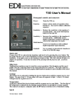
1
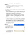
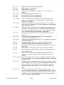
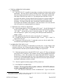
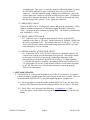
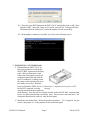
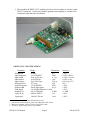
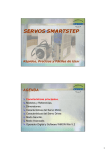
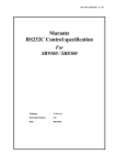
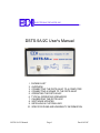
ELECTRONIC DEVICES INC.
P.O. B OX 15037, CHESAPEAKE, V A 23328. PH 757-421-2968 FA X 421-0518
DSTS-5A/2C User's Manual
1. PACKING LIST
2.
3.
4.
5.
6.
7.
8.
9.
10.
DSTS-5A/2C Manual
OVERVIEW
CONNECTING THE DSTS-5A/2C TO A COMPUTER
CONNECTING A SONAR TO THE DSTS-5A/2C
OPERATING THE DSTS-5A/2C
TYPICAL OPERATING SCENARIOS
CALIBRATING THE DSTS-5A/2C
SOFTWARE UPDATES
INSTALLING A CUSTOM LOAD
SPECIFICATIONS AND WARRANTY INFORMATION
Page 1
Doc 010512C
DSTS-5A/2C User's Manual
V1.19
1 PACKING LIST
1.1 The following items are included with the DSTS-5A/2C:
1.1.1 Power transformer. A 9VDC 300mA wall plug power adapter is supplied.
Nominal power requirements are 8 to 12 volts at 200 mA.
1.1.2 A CD with software for controlling, calibrating, and updating the DSTS-4A.
1.1.3 A user's manual.
2 OVERVIEW
2.1 The DSTS-5A/2C sonar test set designed to work with chirp sonar and standard fixed
frequency sonar sets.
2.1.1 HOW IT WORKS
When the transmitted sonar pulse is received, it is digitized, and the period of each
cycle is measured and stored internally. After a delay determined by the depth
setting, the reply pulse is generated from the stored data, resulting in a echo that
faithfully reproduces the frequency of the input pulse cycle by cycle.
2.1.2 CONTROL
All functions such as reply level, depth, and other characteristics for the fish and
bottom echoes are controlled by data sent through the RS-232 port. The included
program “DSTS_terminal.exe” or any terminal program may be used to control the
DSTS-5A/2C.
2.2 OPERATING THE DSTS-5A/2C WITHOUT A COMPUTER
2.2.1 When powered up without the RS-232 connection the DSTS-5A/2C will operate
in the Q-mode, allowing a sonar to be evaluated based on the displayed depth. The
Q-mode generates an echo amplitude based on transmitted power and depth. The
depth is incremented by one foot and the reply level is decreased each time the
sonar transmits a pulse. As the depth increases a point will be reached where the
echo is no longer received. The quality of the sonar can be read from the maximum
depth reading before the echo is lost.
3 CONNECTING THE DSTS-5A/2C TO
COMPUTER
3.1 To install the supplied software,
copy the file “DSTS_terminal.exe”to
directory of your choice. To run the
program, click on it and it will
launch. You must have a serial port
USB/serial adapter to use this
program.
A
a
or
3.1.1 If you do not want to use the
supplied software, you can use
any terminal program, such as
Microsoft HyperTerm. The
DSTS-5A/2C Manual
Page 2
Doc 010512C
parameters should be set for 9600 Baud, 8-bit data, no parity, one stop-bit. Flow
control should be set to none.
3.2 Connect the DSTS-5A/2C to the computer using a standard 9 pin RS-232 cable.
Connect the wall transformer power supply. Status LED 2 will light for six seconds and
the status LED's will sequence one time. After power-up the status LED 3 will glow and
pulse at a one-second rate indicating the DSTS-5A/2C is ready for operation.
3.3 Run the “DSTS-5A/2C Vxxx.exe” program. If everything is connected correctly, the
terminal should display a row of numbers while the DSTS-5A/2C transmits data every
second.
4
CONNECTING A SONAR TO THE DSTS-5A/2C
4.1 Connect a sonar to the IN/OUT connector. Do not connect sonar to the Trig Out
connector or the DSTS-5A/2C will be damaged. If the sonar has a balanced
output, one of the two balanced output wires may need to be connected to the shield
and grounded. Consult the manufacturers manual to determine if one wire and the
shield can be used as ground without damaging the sonar. If you are unsure of the
correct connections for a balanced output, use the EDI BAL-550 accessory. The BAL550 is a balanced-to-unbalanced transformer that has connections for the shield and two
wires, and converts the balanced input to a ground referenced output. The output of
the BAL-550 connects to the DSTS-5A/2C. A short BNC to BNC cable is required.
4.1.1 Apply power to the sonar. When the sounder transmits, the red status LED will
blink indicating that a pulse has been received.
4.1.2 Type a lower case 's' in the “Text to Send” box and click on “Send Text” or press
enter. The characteristics of the sonar's transmitted pulse are displayed on the first
line labeled “Input” , and the output echo pulse data is displayed on the second line,
labeled “Output”.
5 CONTROLLING THE DSTS-5A/2C
5.1 COMMAND STRUCTURE
Most commands are a single alpha character followed by numbers. For instance, 'd250'
followed by pressing the 'enter' key will set the depth to 25 feet. Some commands use
two alpha characters. The frequency shift command 'fn12' will decrease the reply
frequency by adding 12 sample times to the reply period. The command 'cm' will
change the depth calibration to meters. Commands requiring a numerical input such as
the depth will be shown as'dxxxxxx' showing that the command expects a string of up to
6 digits to follow. Commands must end with a CR/LF.
5.2 COMMAND LISTING
5.2.1 'b'
Restores normal operating mode. Used when returning from CW
mode. Default setting.
5.2.2 'Bxxxxx'
Generates a continuous reply at the selected frequency. B100000
produces an output frequency of 100KHz.
DSTS-5A/2C Manual
Page 3
Doc 010512C
5.2.3 'cf'
5.2.4 'cF'
5.2.5 'cm'
5.2.6 dxxxxx
Depth units are set in feet. Default setting.
Depth units are set in Fathoms.
Depth units are set in feet.
Set bottom depth in tenths of a depth unit, i.e., feet, fathoms or
meters.
5.2.7 Dxxxxx
Set fish depth in tenths of a depth unit.
5.2.8 'exx'
Fish echo will be off for xx input pulses.
5.2.9 'Exx'
Fish echo will be on for xx input pulses.
5.2.10 'fnxxx'
Adds xxx sample times to the reply period, reducing the reply
frequency accordingly. New reply frequency is calculated and
returned to the terminal.
5.2.11 'fpxxx'
Subtracts xxx sample times from the reply period, increasing the
reply frequency accordingly. New reply frequency is calculated and
returned to the terminal.
5.2.12 'gxx'
Adds extra cycles to the echo pulse to simulate pulse stretch. 'g12'
will add 12 cycles to the reply. The frequency of the added cycles is
the same as the frequency of the last cycle received from the sonar.
'g0' is the default setting so echo length = input length..
5.2.13 'ixx'
Sets the increment for the fish echo arch emulation in tenths of a
depth unit.
5.2.14 'l'xxx'
Set the bottom echo amplitude from 0 to 255. Each number
represents a 0.3dB change in level.
5.2.15 'L'xxx'
Set the fish echo amplitude from 0 to 255. Each number represents a
0.3dB change in level.
5.2.16 'P'
Additional 10dB attenuator is out of circuit. Default setting.
5.2.17 'p'
Additional 10dB of attenuation is added to the reply level.
5.2.18 'r'
Re-initializes the frequency averaging to the frequency of the next
input pulse.
5.2.19 'R'
Resets depth to 24 ft, reply level to max, and Vprop to 4800f/s.
5.2.20 's'
Stops the auto-send mode where the data is sent to the terminal at
one-second intervals.
5.2.21 'S'
Starts the auto-send mode. Input and output pulse data such as
frequency, amplitude, depth will be sent to the terminal each
second.
5.2.22 't' enters the extended command mode. A list of additional commands will be
sent to the terminal. The extended commands are used in calibrating
the DSTS-5A/2C.
5.2.23 'vxxxx'
Sets the velocity of propagation and stores the new value in eeprom
to be loaded on power-up. The velocity of propagation should be set
in ft/sec if the units are in feet, and m/sec if units are in meters.
Default values for a new DSTS-4A/2C are 4800 ft/sec and 1500
m/sec.
5.2.24 'zxxxx'
Starting with the first cycle, the period of each cycle up to cycle
xxxx is sent to the terminal. If 'z' with no numbers is used, then all
the cycles of the input pulse fr0m the first to last will be sent to the
terminal. This may take considerable time with a large number of
cycles. The data is comma delimited.
DSTS-5A/2C Manual
Page 4
Doc 010512C
6 TYPICAL OPERATING SCENARIOS
6.1 FISH ECHO
6.1.1 The DSTS-5A/2C is capable of generating a secondary echo between the surface
and bottom. This echo can be used to simulate an echo from a fish or other object
above the bottom and will be referred to as a fish echo. The depth, duration and
arch shape of the fish echo can be set. The duration of the fish echo is set by
specifying the number of echoes that the fish will generate as it passes under the
transducer. A more realistic fish echo can be generated by specifying a depth
increment. The depth of the fish echo is decreased for half the duration then
increased for the remainder of the duration. If the increment is set to zero the fish
echo will remain at a constant depth for its duration.
6.2 SETTING UP A TYPICAL FISH ECHO
6.2.1 Set the bottom depth to 25 feet by typing “d250 'enter'”. Set the fish depth to 23
feet by typing “D230 'enter'”. Set the fish echo off time to 20 pulses by typing
“e20 'enter'”. Set the fish on time to 3 pulses by typing “E3 'enter'” and the fish
echo will appear for 3 pulses every twenty pulses and repeat until disabled by
typing “e 'enter”.
6.2.2 The amplitude of the fish echo can be set using the “L” command.
6.2.3 To make the fish echo stay on continuously type “E 'enter' ”. Type “e 'enter' ” to
turn the fish echo off.
6.2.4 To generate a fish arch use the “i” command to enter an value in tenths of the
selected units representing the arch height.
7 CALIBRATING THE DSTS-5A/2C
7.1 The load resistor can change if overheated by too much power. A large change in the
resistance will cause the voltage and reply readings on a sonar to change. The load
resistor should be checked any time abnormal readings are experienced.
7.1.1 Check the load resistance with the DSTS-5A/2C power off. Place an ohmmeter
across the IN/OUT connector. The resistance for the factory installed load should
be 582 ohms +/- 10%. The resistance of a custom load at the IN/OUT connector
should read 22 ohms higher than the value of the installed load resistor. If the load
is out of spec, the unit should be taken apart and the load resistor replaced before
any further calibration or checks are done.
7.1.2 Run the supplied terminal program, DSTS_terminal.exe.
7.1.3 VOLTMETER CALIBRATION
Caution—Do not perform this procedure without a EDI DSTS calibrator
or other comparable pulse source.1
7.1.3.1 The volt meter calibration is in the “extended menu”. Type 't' to enter the
1 The EDI DSTS Calibrator produces a 400 volt p-p pulse burst with a frequency of 204.8 KHz, length of 325 uSec,
and a period of 80 mSec. Droop is less than 10 percent.
DSTS-5A/2C Manual
Page 5
Doc 010512C
extended menu. Then type 'c' to start the voltmeter calibration routine. Connect
the EDI DSTS calibrator or other comparable pulse source to the IN/OUT
connector. After the indicated voltage readings have settled down, type in the
correct input pulse voltage in volts peak-to-peak and press 'enter'. A calibration
factor will be generated and stored in eeprom. Press the reset button and check
that the voltage reads correctly. If not, repeat the calibration.
7.1.4 FREQUENCY CHECK
Connect the DSTS-5A/2C to a frequency counter and press the reset button. Set the
output to continuous frequency of 100 KHz by typing ‘B100000’ followed by
‘enter’. Set output level to maximum by typing 'l255'. The frequency counter must
read 100,000Hz +/- 10 Hz.
7.1.5 REPLY AMPLITUDE CHECK
7.1.5.1 Connect a scope (1 megohm input required) directly to the IN/OUT
connector with a short (< 3ft) cable. Set the frequency to 100 KHz (f10000) and
the level to maximum (l255). The voltage must read 112 mV p-p +/- 7 mV p-p.
This is a fixed factory setting and will not change unless the DSTS-5A/2C has
been damaged by a severe overload.
7.1.6 OPTIONAL REPLY ATTENUATOR CHECK
7.1.6.1 Connect the DSTS-5A/2C IN/OUT connector to a spectrum analyzer. Set
various levels to make sure the attenuator tracks properly. Note that the output
on the analyzer will be low because the 50 ohm input impedance of the
spectrum analyzer loads down the DSTS-5A/2C output. If a high impedance
(>=100,000 ohm) probe is available, the readings will be correct and a level of
255 will produce 50 mV rms. Each decrease in the level will reduce the output
by 0.3 dB. The object is to verify that the attenuator is operating properly.
There are no adjustments.
8 SOFTWARE UPDATES
8.1 The DSTS-5A/2C software can be updated via your RS-232 connection. As software
features are added, periodic update files in hex format may be sent via email. They can
be installed in the DSTS-5A/2C by using the supplied program, “progdsts.exe”.
8.1.1 Put the progdsts.exe program and the updated DSTS-5A/2C.hex file in the same
directory. The illustrations assume the program and hex file are in the c:\ directory.
8.1.2 Go to “Start – run” and type in the following: c:\progdsts.exe -i COMx
yyyyy.hex where x is the connected com port and yyyyy is the name of the hex file
update.
DSTS-5A/2C Manual
Page 6
Doc 010512C
8.1.3 Press the reset (RST) button on the DSTS-5A/2C and quickly click on OK. Note
that after a RST, status led 2 stays on 5 seconds, then gos off. You must click the
OK button while the status led 2 is on for the update to work successfully.
8.1.4 If the update is running successfully you will see the following screen:
9 INSTALLING A CUSTOM LOAD
9.1 Disassemble the DSTS-5A/2C by
first removing the hex nut from the
IN/OUT BNC connector on the front
panel. Refer to illustration 1 and
remove the black plastic outer bezel
on the back panel (the side with the
RS-232 connector) by lifting it near
the center on the top and sides where
the catches are located. When the
bezel is off hold the DSTS-5A/2C so Illustration 1: Exploded view of DSTS-5A/2C
the IN/OUT connector is facing
housing.
upwards and slide the back panel out
of the housing. Save the two lock washers located on the IN/OUT BNC connector and
be sure to replace them during re-assembly. Note: Do not remove the front bezel. The
front panel should not be removed, only the back panel.
9.2 Install the new load resistor, R24 and a parallel capacitance , C31 if required. Be sure
to move the jumper, J5, to the position closest to the front panel.
DSTS-5A/2C Manual
Page 7
Doc 010512C
9.3 Re-assemble the DSTS-5A/2C making sure the two lock washers are in place on the
IN/OUT connector. If necessary bend the ground contact slightly so it contacts the
front panel when the unit is assembled.
Photo 1: DSTS-5A/2C Circuit Board.
10 DSTS-5A/2C SPECIFICATIONS
Parameter
Sample rate
Input frequency
Input width
Input period
Input voltage
Min input level
Output frequency
Output width
Echo depth
Output level
Vprop ft, fm
Vprop mtrs
2
3
4
5
Range
Resolution
40 Mhz
n/a
1.5 to 500 KHz2
25nS
1100 cycles max
0.1 μs
10 to 9999 ms
1 ms
50 to 2500 Vp-p
2 Vp-p
5
50 Vp-p
N/A
1.5 to 500 KHz
25nS
Tracks input pulse
0.1 μs
1 to 100,000 ft/fm/mt 0.1 unit
2uV to 50,000uV
0.3dB
4800 to 5000 f/s
1 f/s
1460 to 1530 m/s
1 m/s
Accuracy
±.01%
±.02% ±20 Hz3
±.02% ±2 cycles
±.02% ±1 ms
±10 Vp-p ±5%4
N/A
±.01%
±.02%
±.01%
±1.0 dB
±.01%
±.01%
Usable to > 550 Khz with reduced amplitude accuracy.
Specified for constant frequency pulse with width greater than 100 uS.
Measured at 200KHz, 400Vp-p with a 325 uSec pulse width.
At 50 Khz. Approximately 120 Vp-p at 500 Khz.
DSTS-5A/2C Manual
Page 8
Doc 010512C
Depth jitter
Baud rate
less than 50 nSec maximum at 1 second depth delay.
9600, 8 bits, no parity, no handshake.
Power requirements: 9 VDC @ 200 mA.
Size and Weight:
6" W by 7"D by 3.5"H. Shipping Wt, 2.1 Lbs.
Depth jitter
Baud rate
less than 50 nSec maximum at 1 second depth delay.
9600, 8 bits, no parity, no handshake.
Power requirements: 9 VDC @ 200 mA.
Size and Weight:
6" W by 7"D by 3.5"H. Shipping Wt, 2.1 Lbs.
WARRANTY INFORMATION
Unit will be repaired free of charge for one year from date of purchase providing there is no
water damage or other evidence of improper use or handling. Purchaser must ship unit
prepaid to address below; EDI will pay the return freight.
For repair, please enclose a note describing the problem and ship to:
ATTN: Service Department
Electronic Devices, Inc.
3140 Bunch Walnuts Road
Chesapeake, VA 23322
USA
Phone: 1-757-421-2968
DSTS-5A/2C Manual
Page 9
Doc 010512C