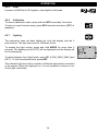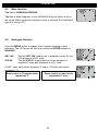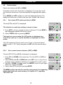
1
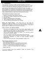
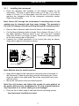
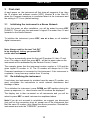
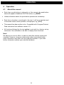
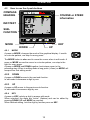
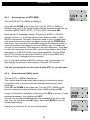
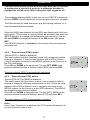
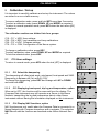
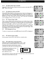
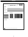
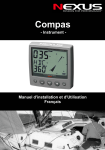
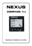
Installation and Operation Manual
0
INTRODUCTION
Introduction
Thank you for choosing Nexus Compass Data instrument. We are convinced that you will
appreciate all the valuable information either you are a cruiser or a racer. It is important
that
you follow the instructions regarding installation and operation.
If the instrument is to be used in a Nexus Network, it is preferable to connected the
Compass transducer to the Server. You must then change the
configuration. Se chapter 5, Calibration / Set-up.
Note in US the Compass Data is named Tactical Data. This manual is valid for both
This manual is written for the NEXUS Compass/Tactical Data instrument version 1.00
Edition: Jul 2000
1
CONTENTS
1 Part specifications .......................................................................................................4
2 Installation...................................................................................................................6
2.1.1 Installing the instrument .........................................................................................7
2.1.2 Installing cable.......................................................................................................8
2.1.3 Connections in Nexus Network...............................................................................8
2.1.4 Connection of log transducer..................................................................................9
3 First start ...................................................................................................................10
3.1 Initialising the instrument in a Nexus Network .........................................................10
3.2 Re-initialising the instrument ...................................................................................10
4 Operation ..................................................................................................................11
4.1 About this manual...................................................................................................11
4.2 How to use the 4 push-buttons................................................................................12
4.2.1 MODE .................................................................................................................12
4.2.2 DOWN.................................................................................................................12
4.2.3 UP .......................................................................................................................12
4.2.4 KEY .....................................................................................................................12
4.2.5Clear.....................................................................................................................13
4.2.6 Calibration ...........................................................................................................13
4.2.7 Lighting................................................................................................................13
4.3 Main function ..........................................................................................................14
4.4 Analogue function ...................................................................................................14
4.5 Sub-functions .........................................................................................................15
4.5.1 Set a steer (STR) reference direct in MEM............................................................15
4.5.2 Set a numeric steer reference (STR) in MEM........................................................15
4.5.3 Advanced use of (STR) MEM ...............................................................................16
4.5.4 Steer referens [AWA], option................................................................................16
4.5.5 Steer referens [BTW], option ................................................................................17
4.5.6 Steer referens [CTS], option .................................................................................17
4.5.7 Tactical use of [MEM] ..........................................................................................18
4.5.8 Battery voltage [BAT] ...........................................................................................18
4.5.9 Boat speed [BSP], option .....................................................................................18
4.5.10 Trip log [TRP], option .........................................................................................19
4.5.11 Water temperature [TMP], option .......................................................................19
4.5.12 Dead reckoning [CMG / DMG]............................................................................19
4.5.13 X-track error, [XTE], Option................................................................................19
4.5.14 In a small NEXUS network .................................................................................19
5 Calibration / Set-up....................................................................................................21
5.1 C10 User settings ...................................................................................................21
5.1.1 C11 Select the dampening ...................................................................................21
5.1.2 C13 Displaying boat speed, trip log and temperature, option ................................21
5.1.3 C14 Display NAV functions, option.......................................................................21
5.1.4 C15 Beep when key is pressed.............................................................................22
5.1.5 C16 Referens pointer On/OFF..............................................................................22
5.1.6 C17 ”Knock Timer” KTR.......................................................................................22
5.2 C20 Calibration of Log ............................................................................................22
5.2.1 C21 Select unit for speed .....................................................................................22
5.2.2 C22 Calibration of log transducer .........................................................................22
5.2.3 C23 Unit for temperature......................................................................................23
5.2.4 C24 Temperature offset .......................................................................................23
5.3 C30 Compass Settings ...........................................................................................23
5.3.1 C31 True or magnetic course, MAG .....................................................................23
2
CONTENTS
5.3.2 C32 Magnetic deviation, VAR...............................................................................23
5.3.3 C33 Autodeviation................................................................................................23
5.3.4 C34 Check the Autodeviation ...............................................................................23
5.3.5 C35 Clear the Autodeviation.................................................................................24
5.3.6 C36 Adjust the Compass alignment .....................................................................24
5.3.7 C37 Off course alarm...........................................................................................24
5.3.8 C68 Roll adjustment ............................................................................................24
5.3.9 C69 Pitch adjustment...........................................................................................25
5.4 C70 Configure Nexus ..............................................................................................25
5.4.1 C71 HDC-master .................................................................................................25
5.4.2 C72 Log-master ...................................................................................................25
5.4.3 C73 Function on terminal In3 ...............................................................................25
5.4.4 Connection of trim button.....................................................................................26
5.4.5 C74 Demo mode..................................................................................................26
6 Maintenance and fault finding ....................................................................................27
6.1 Maintenance ...........................................................................................................27
6.2 Fault finding............................................................................................................27
6.2.1 General................................................................................................................27
6.2.2 Fault - action........................................................................................................27
6.2.3 Error messages ...................................................................................................28
7 Specifications ............................................................................................................29
7.1 Technical specifications ..........................................................................................29
7.2 Nexus data bus introduction and user policy............................................................29
8 Optional Accessories .................................................................................................30
9 Abbreviations.............................................................................................................32
10 Warranty .................................................................................................................36
3
PART SPECIFICATIONS
1
Part specifications
Nexus Compass Data is delivered with all parts for mounting. Check prior
to installation.
Compass Data instrument
Qty.
1
1
1
1
1
1
1
5
5
4
4
1
1
2
Description
Reference
Instrument, Nexus Compass Data
Instrument front cover
Drill template
Installation and user manual
Warranty card
National distributors list
Power cable, red and black, 3 m (9 ft)
Extra wire protectors, 0,25 mm (1/100”)
Extra wire protectors, 0,75 mm (1/32”)
Mounting screws for the instrument
Round rubber covers
Tube of silicon grease
Connection cover
4-pol screw terminal
1
2
3
4
5
6
7
8
8
9
9
9
9
9
Additional items with Compass Data Instrument complete with
transducer
1
4
Compass transducer Nexus
Mounting screws for Compass
10
12
Registering of this product
Once you have checked that you have all the listed parts, please take
time to fill in the warranty document and return it to your national
distributor.
By returning the warranty card, it will assist your distributor to give you
prompt and expert attention, in the event of your experiencing difficulties
with this product. Keep your proof of purchase. Also, your details are
added to our customer database so that you automatically receive new
product catalogues when they are released.
4
PART SPCIFICATIONS
5
INSTALLATION
2
Installation
The Compass transducer is either connected directly to the Nexus
Compass Data instrument or by use of the connection kit art.no. 21453.
The kit is used when the NEXUS log transducer are installed to form a
sole Compass Data system without the NEXUS Server. In a larger
NEXUS system, the installation may preferably include the Nexus Server
adding NMEA in/out, and where all transducers may be connected. All
data including power will then pass along in one single NEXUS network
cable, making installation, maintenance and service very easy.
The installation includes 6 major steps:
1. Read the installation and operation manual.
2. Plan where to install the transducers and instruments.
3. Run the cables.
4. Install the transducers and instruments.
5. Take a break and admire your installation.
6. Learn the functions and calibrate your system.
Before you begin drilling .. think about how you can make the
installation as neat and simple as your boat will allow. Plan where to
position the transducers, the Server and the instruments. Think about
leaving space for additional instruments in the future.
A few ”do nots” you should consider:
− Do not cut the cables too short. Allow extra cable length at the
instrument or at the Server so it can be disconnected for inspection
without having to disconnect all attached cables.
− Do not place sealant behind the display. The instrument gasket
eliminates the need for sealant.
− Do not run cables in the bilge, where water may accumulate.
− Do not run cables close to fluorescent light sources, engine or radio
transmitting equipment, in order to avoid possible electrical
disturbances.
− Do not rush, take your time. A neat installation is easy to do.
The following material is needed:
Wire cutters and strippers.
Small and large Philips and small flat head screw driver.
Hole saw for the instrument clearance hole 63 mm (2½").
2.8 mm (7/64") drill for the mounting holes in wood.
3.2 mm (1/8") drill for the mounting holes in fibre glass.
Plastic cable ties.
If you are doubtful about the installation, obtain the services of an
experienced technician.
6
INSTALLATION
2.1.1
•
Installing the instrument
Place the adhesive drill template on the desired location for the
instrument. Drill the 4 screw holes using a 2.8 mm (7/64") drill for
wood or 3.2 mm (1/8") for fibre glass. Use a 63 mm (2½") hole saw to
machine the clearance hole for the instrument connection socket.
Remove the template.
Note: Never drill through the instruments 4 mounting holes as the
gaskets may be damaged and thus cause leakage. The warranty is
not valid for damage caused by drilling through the mounting holes.
•
•
•
Run the Nexus Network cable from the Server to the instrument.
Cut the Nexus Network cable to length. Peel off about 35 mm (1,4") of
the cable insulation. Remove about 6 mm (1/4") from the 3 isolated
wires (the 4th wire is an earth / screen). Attach the 4 cable protectors
to the wires using a pair of flat pliers.
Connect the 4 cable protectors to the 4-pole jack plug as shown.
Apply silicon paste to all areas as shown.
Silicon paste
Silicon paste
Note: Must be done to avoid corrosion.
•
•
Apply silicon paste to the instrument connection pins at the back of
the instrument. Press the jack plug onto the instrument pins. Press
down the cable in the cable leads. Mount the connection back cover
with the screw.
Mount the instrument in the pre-drilled position.
Note! Use all 4 screws, and tighten the screws (in cross pattern) so
the gasket will be evenly compressed to 1/3 of its original thickness.
Very important for a correct sealing to avoid leakage!
•
Press on the 4 rubber caps to seal and hide the mounting screws.
Your instrument installation is done!
7
INSTALLATION
2.1.2
Installing cable
The power cable is connected via a 3A fuse from the battery or at the
boats fuse panel and direct to the instrument or Server. One red and one
black power wire is included. Note, set C71 ON (see 5.5.1).
Always connect a 3 AMP fuse between Power supply and
instrument.
Screen
Green
Yellow
White
Black
Transducer
Red
3A Fuse
2.1.3
Connections in Nexus Network
If you already have a Nexus Network i.e. a Server, it is more practical to
connect the transducer to the Server due to the single instrument cable
installation. Note, set C71 OFF (see 5.5.1).
Transducer
Server
The instrument is then connected to the Server’s Nexus Network terminal
(pin 5, 6, 7 and 8) or at any NEXUS instruments terminal .
From NEXUS Server or
other NEXUS
instrument
8
INSTALLATION
2.1.4
Connection of log transducer
If you have another log instrument i.e. a Nexus log, a Star log, a D-20
log, a 2200 log or a 220 log, you may connect the single log pulse wire
from that instrument to the Compass Data instrument terminal 4.
From log transducer,
NEXUS, Star, D-20,
2200 or 220
3A Fuse
If you don’t have a log instrument, but want to install a log transducer,
use the connection box (Art. no: 21453).
9
FIRST START
3
First start
At each power on, the instrument will first show all segments lit up, then
the ID number and software version [VER]. Number 8 is the fixed ID
when the Compass transducer is connected direct at the instrument and
the setting in C71 is on (default setting).
3.1
Initialising the instrument in a Nexus Network
At the first power on after installation, you will be asked to press KEY
[PrSKEY]. This will give the instrument a logical ID number from 16 and
upwards on the Nexus Network.
To initialise the instrument, press KEY, one at a time, on all installed
digital instruments,.
Note: Always wait for the text ”Init OK”
to be displayed, before you press KEY
on the next instrument!
The Server automatically gives the first unit ID number 16, then 17 and
so on. The order in which you press KEY, will be the same order as the
instruments will be addressed by the Remote Control, if used.
The example shows that the instrument version number is 1.00 and the
given logical ID number is 16. The ID number will always be 8 if the
Compass transducer is connected to this instrument. If the instrument is
a repeater, it may have any number from 16 and up.
3.2
Re-initialising the instrument
If and when two instruments by mistake have the same ID number, you
must re-initialise the instruments to avoid network disturbance and
blockage of data.
To re-initialise the instrument, press DOWN and UP together during the
power up sequence, i.e. when version and ID numbers are displayed.
The display test is then re-started on all instruments and you will be
asked to press KEY on each instrument as explained above.
Note! If you do not succeed to re-initialise, we suggest you disconnect
(just pull out the connection plug) all, except one of the instruments that
had the same ID number, then repeat the above procedure. Reinstall the
instruments and redo the ”PRESKEY” procedure.
10
OPERATION
4
Operation
4.1
About this manual
•
Each time a push-button is referred to in this manual, the push-button
name will appear in bold and CAPITAL letters, e.g. MODE.
•
Unless otherwise stated, the push-button presses are momentary.
•
Each time a function is mentioned in the text, it will be in brackets and
in the same format, where possible, as displayed, e.g. [MEM].
•
This manual has been written to be: Compatible with Compass/Tactical
Data instrument from software version 1.0.
•
All functions followed by the text option is not valid in a factory set-up
instrument. See calibration to be able to display these functions.
Note!
We have put in a lot of effort, in order to make this manual correct and
complete. However, since we continuously make our products better,
some information may differ from the products functions. If you need
further information contact your national distributor.
11
OPERATION
4.2
How to use the 4 push-buttons
COMPASS
HEADING
COURSE or STEER
information
INFOTEXT
SUBFUNCTION
KEY
MODE
UP
DOWN
4.2.1
MODE
A press on MODE, changes the mode of the graphical display. It scrolls
in a circular pattern, one step for every press.
The MODE button is also used to move the cursor when in edit mode. A
press on MODE moves the cursor in a circular pattern, one step to the
right for every press.
A press on MODE and DOWN together, back steps cursor to the
preceding step. When in editing mode a long press (>2sec) on MODE will
escape from that editing mode.
4.2.2
DOWN
A press on DOWN moves to the next sub-function.
In edit mode it decreases a digit by one.
4.2.3
UP
A press on UP moves to the previous sub-function.
In edit mode it increases a digit by one.
4.2.4
KEY
A press on KEY unlocks a digit to access edit mode.
When unlocked, the digits are ”active” (flashes) and can be edited by
pressing DOWN, UP and MODE as required.
When finished editing, lock the digit by another press on KEY.
12
OPERATION
4.2.5
Clear
A press on DOWN and UP together, clear digits in edit mode.
4.2.6
Calibration
To access calibration mode, press and hold KEY more than 2 seconds.
To return to main function mode, press KEY when the text return [RET] is
displayed.
4.2.7
Lighting
The instrument uses red back lighting for both the display and the 4
push-buttons. The light can be set at 4 different levels.
To access the light control, press and hold MODE for more than 2
seconds. The flashing text [Lit OFF] will be displayed and the display will
be lit momentarily.
To select between the 4 light levels, press UP: [LOW], [MID], [MAX] and
[OFF]. To lock the selected level, press KEY.
The selected light level will be copied to all Nexus instruments connected
to the system. When the lighting is on, it is not possible to reduce or turn
off the light individually.
13
&
OPERATION
4.3
Main function
Top data is COMPASS HEADING.
Top data is either magnetic or true HEADING and your choice is set in
the set-up. When magnetic Compass course is selected, the small MAG
sign is lit on the LCD.
4.4
Analogue function
Press the MODE button to change from Compass heading to steer
reference. The LCD arrow will then point at the text STEER instead of
HEADING.
HDC 360°°
STR 60°°
The text HDC 360° means true or magnetic course for the.
LCD pointer in a 360° scale
The text STR 60° means that the course deviation is
amplified 3 times and displayed in a 60° scale.
At 360° scale, each sector represent 5° and at 60°scale each sector
represent 1 2/3°.
Each sector in Compass mode
represents 5°
Three sectors in steer mode
represents 5° error
14
OPERATION
4.5
Sub-functions
Select sub-function with UP or DOWN.
Information text for the sub-function is displayed. You may also ”park”
your favourite function so it will automatically be displayed after power
on.
Press MODE and KEY together to ”park” the displayed function. The
display will flash once to confirm that you have ”parked” the function.
4.5.1
Set a steer (STR) reference direct in MEM
The text [STR] and [OFF] is displayed.
This function is used when setting a course to steer.
1. Press KEY to set your present course as reference. The text MEM is
then displayed together with the set course.
2. Select STEER mode by pressing MODE
The boat is on course when the LCD pointer is displayed as a
vertical line strait up. A course deviation is displayed as a filled
sector.
The LCD segments will lit up one by one to form a ”course deviation”
sector of max +/- 30°. Every new press on KEY will set a new course in
MEM
4.5.2
Set a numeric steer reference (STR) in MEM
The text [STR OFF] or [MEM] (if activated), is displayed.
1. Press UP and DOWN at the same time. The text [OFF] or [MEM] is
flashing.
1. Select [MEM] with UP or DOWN and press KEY, now, a copy of your
present course is flashing, allowing you to adjust the course to steer.
2. Use UP or DOWN to change value, use MODE to move to next figure.
When set, confirm with KEY.
3. Select steer [STR] mode by pressing MODE
The MEM function can also be used for racing since it is supporting
both a starboard and a port memory. Se chapter 4.5.7 regarding
TACTICAL use.
15
OPERATION
4.5.3
Advanced use of (STR) MEM
The text [STR OFF] or [MEM] is displayed.
Press UP and DOWN at the same time. The text [OFF] or [MEM] is
flashing, select one of the following four different steering modes that are
available; [MEM], [AWA], [BTW] , [CTS] or [OFF] and press KEY.
Each function is explained in detail. The function [STR] is a NEXUS
network function, i.e. it will transmit the steer reference data to other
NEXUS instruments. The steer information used on the Compass Data
instrument is functioning within the same concept as the STEER Pilot
instrument. The instrument is especially designed for displaying steer or
Compass heading information in the most efficient way. You may also
use one or more external TRIM buttons to set new references. To be able
to utilise the wind steer function AWA, you will need either a Wind Data
instrument, or a NEXUS Server with a wind transducer. For the [BTW]
and [CTS] functions you will need a NEXUS GPS or any NMEA GPS
,Decca or Loran C navigator to be connected.
Also, if you have installed a NEXUS Autopilot, and it is activated, you
may change the course or wind angle by using the STR function.
You can not activate or turn the pilot off with STR, so use with care !
4.5.4
Steer referens [AWA], option
The text [OFF] or [MEM] is displayed.
This function may be used when sailing upwind or downwind, where
Compass course is chosen to be the secondary steer priority, after
windangle.
Press UP and DOWN at the same time. The text [OFF], [MEM] or the
previous selected function is flashing, select [AWA] and press KEY.
A copy of the present windangle is flashing, press KEY to accept, or enter
preferred windangle, then confirm with KEY.
You will now see the text WA flashing with a pointer at the left or right
side. For now, just press the KEY again, then press MODE to see the
closed hauled angle.
Example, you have set 40° as your tacking angle.
16
OPERATION
The boat is sailing with the pre-set wind angle when the LCD pointer
is displayed as a vertical line strait up. A windangle deviation is
displayed as a filled sector. When sailing too high, segments are
The windangle referens [AWA] is also sent out to all NEXUS instruments
and the STEER Pilot will also show you the deviation from your set angle.
The AWA can also be used downwind, as a jibe warning indicator, or to
keep the fastest downwind speed.
When the [AWA] was selected, the text [WA] was flashing with a left or a
right pointer. This function is used to perform an automatic tack when the
NEXUS Autopilot is installed (and activated for wind steering). Use the
UP and DOWN to change the direction of the WA pointer, then press
KEY.
Your NEXUS Autopilot, if activated in wind mode, will now perform an
automatic tack.
4.5.5
Steer referens [BTW], option
The text [OFF] or [MEM] is displayed.
This steer function will give Compass course, true or magnetic relative
bearing to Waypoint. It must be used together with a GPS or Decca/
Loran C navigator connected to the NEXUS network (at the Server or at
the GPS instrument).
Press UP and DOWN at the same time. The text OFF, MEM or the
previous selected function is flashing, select [BTW] and press KEY.
The steer referens [BTW] is automatically calculated.
4.5.6
Steer referens [CTS], option
The text [STR OFF] or [MEM] is displayed.
This steer function will give course to steer, true or magnetic relative
bearing to Waypoint, including compensation for drift. It must be used
together with a GPS or Decca/ Loran C navigator connected to the
NEXUS network (at the Server or at the GPS instrument). The NEXUS
log transducer must also be installed.
Press UP and DOWN at the same time. The text [OFF], [MEM] or the
previous selected function is flashing, select [CTS] and press KEY.
The steer reference [CTS] is automatically calculated.
Hints !
Even if your Compass is un-deviated, the CTS function will anyway tell
you the optimum course to sail !
17
OPERATION
The CTS function gives you the shortest way to sail towards the
Waypoint. Tide must however be taken into consideration, since it
will give a time dependant drift on the boat.
4.5.7
Tactical use of [MEM]
Function [MEM] is used to discover the smallest of wind shifts during
upwind or downwind sailing, but it is your tactical decision wheter to tac or
to stay on course. The Compass Data instrument will automatically keep
track on wheter you are using the starboard or port MEM if the course
difference between each trim is more then 45º. There is also a new function
called [KTR] (Knock TimeR), giving you the time spent i seconds when
sailing below a preset ”knock Angle”. Both [MEM] and [KTR] will help you
to get a very good ”picture” over actual windshifts, both in size and time.
How does it work ?
On the optimum compass heading, press the trim or KEY button to store
your present course in the memory called MEM. Your actual course is
then constantly compared with MEM and displayed as a lift or as a
header. Each time you press trim or KEY, a new reference course is set.
How to use the MEM function:
When you are sailing at a good speed and with the sail trimmed, press
trim or KEY. The Compass Data will then store the present course in
memory MEM as a reference. If you then have a lifter, press TRIM again,
but if you have a header more then 5º-10º, tack.
After you tack, re-trim the sails and get a good boat speed before you press
trim or KEY again. Now you have set a new reference in the memory.
Whenever you get a lifter, press TRIM, but when you get a header, tack. Your
previous trim reference will automatically be displayed and used.
Now, add the KTR timer
The timer must first be activated. This is done by setting the CAL value
C-17 to the maximum angle where you consider your boat to be pushed
off course, i.e. where you normally would tac when getting a header. See
more under [KTR] setup.
4.5.8
Battery voltage [BAT]
The text [BAT] will display battery voltage. The voltage is measured
inside the instrument and will not compensate for any voltage drop
caused by installation.
4.5.9
Boat speed [BSP], option
The text [BSP] will display boat speed (water speed). The text [BSP] will
toggle with selected unit, i.e. (KTS), (KMH) or (MPH).
As an option, you may add or remove displaying boat speed [BSP],
trip log [TRP] and water temperature [TMP]. See calibration.
18
OPERATION
4.5.10
Trip log [TRP], option
The text [TRP] is displayed and will show trip distance from 0.00 to 99.9
nautical miles, kilometre or miles. After 99.9, 0.00 is displayed. Clear trip
by pressing UP and DOWN together.
4.5.11
Water temperature [TMP], option
The text [TMP] is displayed with water temperature in Celsius or
Fahrenheit.
This function requires a Nexus or Star log transducer.
4.5.12
Dead reckoning [CMG / DMG]
This function requires both Compass and Log transducers.
The text [CMG] (Course Made Good) is first displayed, then, after some
seconds the text [DMG] (Distance Made Good) is displayed. The two
functions are alternating. When the instrument is powered up, the
CMG/DMG function is cleared. Then, while underway, the function will
continuously calculate the shortest travelled distance [DMG] and the
averaged travelled course [CMG], from start or reset.
You may clear and restart the dead reckoning manually by pressing UP
and DOWN simultaneously.
4.5.13
X-track error, [XTE], Option
To get this function, set NAV = On C14 (See 5.1.4).
The text [XTE] is displayed shortly when this function is selected, then a
symbolic ”boat” is displayed on one side of the ”road” which is displayed
as three vertical lines.
Your ”boat” will be displayed on the right or left side of the symbol. The
distance is also displayed and can be in either Nautical mile, Km or
Miles.
4.5.14
In a small NEXUS network
The Compass Data instrument can be used in a small Network together
with the Speed log, Multi Repeater or analogue instruments, without a
Server.
When both the log and Compass transducers are installed at the
Compass Data instrument, we recommend you to install by use of the
connection kit art.no. 21453. Only one cable will then carry all the signals
between the instrument and the connection box. Additional NEXUS
instruments may be connected direct at the Compass Data instrument.
One NEXUS power/data cable will then go to the additional Multi or Log
instruments. (See 2.1.4).
19
When using the Compass Data in a Network with more then 3 transducers,
we recommend you to use the Nexus Server. One Nexus power/data cable
is used to connect all instruments. You will have NMEA 0183 in/out. Depth
information will (if used) be repeated at more than one NEXUS instrument.
Network bonus function:
When you are using the race timer on the Multi or Log instrument, a
graphical countdown timer will pop up the last 60 seconds.
In this example there is 45 seconds to the start.
20
CALIBRATION
5
Calibration / Set-up
It is important to carefully calibrate and set-up the instrument. The values
are stored in a non volatile memory.
To access calibration mode, press and hold KEY more than 2 seconds.
To select a calibration code, press DOWN, UP and MODE as required.
To return to normal operation mode, press KEY when the text return [rEt]
is displayed.
The calibration routines are divided into four groups:
C10 - C17 = USR, User settings.
C20 - C24 = BSP, Log transducer and temp calibrations.
C30 - C37 = HDC, Compass settings.
C70 - C74 = CON, Configuration of the Nexus system.
To change a calibration value, press KEY.
To select calibration value, press DOWN, UP and MODE as required.
To lock the selected value, press KEY.
5.1
C10 User settings
To return to normal mode, press KEY when the text [rET] is displayed.
5.1.1
C11 Select the dampening
The dampening will effect wind angle, wind speed, boat speed and VMG.
Dampening is between d0 (0s) and d9 (1’20).
To change the dampening, press KEY and change with UP or DOWN
and enter with KEY.
5.1.2
C13 Displaying boat speed, trip log and temperature, option
When set to OFF, the functions will be removed from the display. The
Compass Data instrument may still operate as a Server in the Nexus
Network, transmitting the log and temperature data to other Nexus
instruments without having the information displayed on this instrument.
5.1.3
C14 Display NAV functions, option
NAV functions are only useful when the Compass Data is connected in a
Nexus Network with Compass transducer and a navigator. The selection
NAV On will add the functions as described under Nexus Network See
4.5.
21
CALIBRATION
5.1.4
C15 Beep when key is pressed
Setting KEY On will make a beep at every key press, and when KEY is
OFF. There is no beep.
5.1.5
C16 Referens pointer On/OFF
Setting REF On will show a reference pointer in the true direction as a
steer indicator in the Compass graphical mode. When set to OFF, no
reference indicator will be visible. When the indicator is activated and a
MEM course is set, this pointer will slowly ”blink” and when overlapping
your Compass pointer, you are on course.
5.1.6
C17 ”Knock Timer” KTR
This is a race sailing function that will help you to decide when to tack.
When activated, a ”knock timer” will pop up when you are sailing lower
than the ”knock angle”. When the ”knock angle” is set to 00 it is OFF.
Example, when KTR is set to 15° and you are ”knocked” i.e. sailing 15°
lower than the ”reference set” course for more than 5 seconds, a timer
will pop up, telling you the elapsed time spent at ”knocked” angle. Also
read chapter 4.5.3 Tactical use of MEM.
5.2
C20 Calibration of Log
To return to normal mode, press KEY when the text [rET] is displayed.
5.2.1
C21 Select unit for speed
Unit for speed, knots (KTS), km/h (K/h) or miles/h (m/h).
5.2.2
C22 Calibration of log transducer
Calibration value for speed and distance (1.00 - 1.99).
Drive the boat a measured distance at normal speed.
Compare the distance with the trip counter.
Calculate the value with the following formula.
True distance from the sea chart:
Log trip counter distance:
The current calibration value:
New calibration value:
T
L
C
N
If you suspect a current in the water, drive the boat in both directions and
divide trip counter distance by two.
22
CALIBRATION
If the Compass Data is installed with Nexus Server where the log is
already calibrated, no further calibration is needed.
5.2.3
5.2.4
C23 Unit for temperature
Select degree Celsius [C] or degree Fahrenheit [F].
5.2.5
C24 Temperature offset
By adding a positive or [-] negative value here, it will be added as an
offset before displayed as the temperature.
5.3
C30 Compass Settings
To return to normal mode, press KEY when the text [rET] is displayed.
5.3.1
C31 True or magnetic course, MAG
This function will display bearing, course and Wind direction as true or
magnetic. Select [On] to display all as magnetic, the LCD will then
indicate:
Select [OFF] to display all as true.
5.3.2
C32 Magnetic deviation, VAR
Set the deviation direction first, i.e. [+E] (East) or [W] (West), then enter
the magnetic value in 1/10 of a degree.
5.3.3
C33 Autodeviation
This function is used to autodeviate your Compass. Take the boat into a
turn, in calm sea, when steady, press KEY to start.
The text [DEV] starts flashing and a LCD sector will show you the course
where to end. When you have taken the boat through the minimum 360°
turn, press KEY again, and if successful, the text [DEV Atd] will appear
again. If you read ERR 17, the Compass magnetic variation have been
too small. That is, if you either interrupted the deviation too soon by
pressing KEY before done, or if the Compass is affected by strong
magnetic distortion.
5.3.4
C34 Check the Autodeviation
This function is used to check your Autodeviation. Make a new
Autodeviation in calm sea (during the evening) as described in 5.3.3, and
23
CALIBRATION
you may (or not) take the boat the opposite direction as when
Autodeviated.
The text [CHK] starts flashing and a pointer will show you the course
where to end. When you have taken the boat through the minimum 360°
turn, press KEY again, and if successful, the text [CHK Atd] will appear
again, otherwise, ERR 17 or ERR 19 will appear, i.e. the difference
between the last Autodeviation and this Autocheck is to big to be
accepted. Make a new Autocheck, and if you still get ERR 19, make a
new Autodeviation since the last one was probably disturbed.
When the Autocheck is OK, the Compass will store the average result
from both Autodev and Autocheck.
5.3.5
C35 Clear the Autodeviation
If you by any reason prefer to reset the deviation created by the
Autodeviation function, press KEY when text [CLR Atd] is displayed, you
are now asked to confirm the flashing text YES by another press on KEY,
or select no by use of UP or DOWN button, then KEY.
5.3.6
C36 Adjust the Compass alignment
This function is used when the Compass is giving a constant course
error, i.e. it is not mounted exactly aligned as the boat (there is no need
to mount the transducer at the boats centreline). Make sure that the local
magnetic variation is entered before you make the alignment adjustment,
otherwise you are unable to see the difference between local magnetic
variation and alignment error. The Compass may be installed reversed
180° , but never at perpendicular, or 90° relative the centreline.
Press the KEY and adjust [ADJ] the angle by entering the error. If you
want to add 5° enter 005°. If you want to subtract 5° enter 355° (360- 5).
5.3.7
C37 Off course alarm
This function is used to set a course alarm that will be activated when the
boats average course is more then set value. The text [OCA OFF] is
displayed. Press the KEY to enter the maximum allowed course
error, then press KEY again.
This function is filtered for 30s to avoid false alarms such as when
sailing in heavy sea. Set to 00 will turn alarm OFF.
5.3.8
C68 Roll adjustment
This adjustment is valid only if roll is selected in C73 (you have to exit
and enter the calibration again after C73 is set to Roll).
Adjustment of the roll offset. Mount the roll transducer according to the
instructions. Adjust the offset so the roll is displaying 00° when the boat
is horizontal. By entering a minus sign [-] in front of the value the roll will
be decreased by the value. When the offset is without a minus sign, it will
be added. When a roll transducer is connected, both wind speed and
24
CALIBRATION
wind angle will be compensated for the roll and thus increasing the
accuracy.
The roll sensor is not available at the time for this manual.
5.3.9
C69 Pitch adjustment
This adjustment is valid only if roll is selected in C73 (you have to exit
and enter the calibration again after C73 is set to Roll).
Adjustment of the pitch offset. Mount the pitch transducer according to
the instructions. Adjust the offset so the pitch is displaying 00° when the
boat is horizontal. By entering a minus sign [-] in front of the value the roll
will be decreased by the value. When the offset is without a minus sign, it
will be added.
The pitch sensor is not yet available (at mars 1997).
5.4
C70 Configure Nexus
To return to normal mode, press KEY when the text [rET] is displayed.
In the configuration you will be able to tell the Nexus Network where you
have installed the log and wind transducer.
This is important because you may optionally install those transducers at
the Server instead of the instrument.
5.4.1
C71 HDC-master
[On] = the Compass transducer is connected at the Compass Data
instrument.
[OFF] = the wind transducer is connected at the Nexus Server.
5.4.2
C72 Log-master
[On] = the log transducer is connected at the Compass Data instrument.
[OFF] = the log transducer is connected at the Nexus Server.
5.4.3
C73 Function on terminal In3
Select function on the terminal pin 3. The following functions are
available:
If other function then water temperature is selected, you may still use the
water temperature function by connecting the NEXUS log transducer at
the Server or at the Wind Data instrument.
[TMP]
[TRM]
function.
[STR]
[MOB]
[Roll]
Standard temperature function for the log transducer.
Use the external trim button for the SPEED Trim
Use the external trim button for the STEER Pilot function.
Use the external trim button for the M.O.B. function.
Use the roll sensor to compensate wind speed and angle.
25
CALIBRATION
(Not yet available, at the time for printing this manual).
When the selection roll is made, further settings in calibration can be
made to correct the offset angle. See C68 5.4.8.
When Speed TRriM [TRM] is selected, a press on the external trim button
will transmit the trim command on the Network. To be able to set both
steer and trim reference, the optimum way is to connect one trim button
for speed to the Compass Data instrument and one trim button for steer
at the Server. Such an installation gives you the opportunity to trim both
speed and steer with separate buttons.
5.4.4
Connection of trim button
Connect the trim button as per the drawing. The
button should make a short connection when
pressed. It is also possible to connect more than
one button in parallel, for example one on
starboard and one on port side.
Article number
for the push button:19763.
5.4.5
C74 Demo mode
The Compass Data instrument has a built in demonstration mode. All
values are simulated in this mode. It is convenient to learn the functions
of the instrument by using this mode.
Every 7th second the text DEM will appear to alert you that demo mode is
selected.
26
MAINTENANCE AND FAULT FINDING
6
6.1
•
•
•
•
•
•
Maintenance
To clean the instrument, use only mild soap solution and rinse with water.
Do not use detergents or high pressure washing equipment.
At least once a year, check all your connections and apply additional
silicon paste at each connection point.
Always use the instrument cover for protection, when not in use.
Storing transducers and instruments when not in use for longer periods: It
is advisable to remove the instruments and transducers, and store them
inside the boat or at home in room temperature, if possible.
6.2
•
Maintenance and fault finding
Fault finding
Before you contact your Nexus dealer, and to assist your dealer to give
you a better service, please check the following points and make a list of:
All connected instrument and transducers, including their software
versions.
Nexus Network ID numbers for each instrument (displayed at power up).
6.2.1
General
In most cases, the reason for faults in electronic equipment is to be found
in poor installations. Therefore, always first check that:
•
•
•
•
•
•
•
•
•
•
installation and connection is made per instructions for instrument and
transducers, (see 2.1.1).
screw terminals are carefully tightened.
no corrosion on any connection points.
no loose ends in the wires causing short cuts to adjacent wires.
cables for damage, that no cables are squeezed or worn.
battery voltage is sufficient, should be at least 10 V DC.
the fuse is not blown and the circuit-breaker has not opened.
the fuse is of the right type.
two instruments do not have the same ID number, (see 3).
the dampening for course and speed is equally set in all instruments (The
dampening is individually set for each instrument).
Fault - action
•
•
1. Compass: No reading [ --- ] or wrong headCheck that setting C71 is
according to your installation.
Check that the local magnetic variation is properly set C32.
Make sure the Autodeviation have been carried out. C33
•
Check for magnetic disturbences.
Make sure the transducer is aligned correctly, (see C36, 5.3.4).
27
MAINTENANCE AND FAULT FINDING
•
•
•
•
2 Speed and distance functions: No reading [ --- ]
C13 should be ON. See 5.1.2
Check that setting C72 is according to your installation.
Check that the impeller is rotating easy and freely i.e. is free from
vegetation
Check that there is no remaining anti fouling paint inside the through hull
fitting.
6.2.2
Error messages
The following messages may appear on the display:
ERR 2
ERR 3
ERR 10
ERR 11
ERR 17
ERR 18
ERR 19
Nexus Network is missing, check colour coded connections
No Network data received within a given time.
Range error caused by incorrectly entered value, e.g. 430°.
Remote command that can not be performed.
Too small magnetic variation.
Busy with Autodeviation
Autodeviation check error, repeat again.
If other messages than the above appears on the Compass Data
instrument, contact your Nexus dealer.
28
SPECIFICATIONS
7
7.1
Specifications
Technical specifications
Dimensions:
Instrument cable:
Power supply:
Power consumption
Instrument:
Log- and temp sensor:
Wind transducer:
Temperature range:
Weight:
Enclosure:
Compass Data instrument: 110 x 110 mm.
(4.3 x 4.3 inch)
0.4 m (16 inch)
12 V DC (10-16 V). The instrument is polarity
protected.
0,08 W
0.8 W (at max illumination)
12 mW
50 mW
Storage: From -30°C to +80°C.( -22°F to 176°F)
Operation: From -10°C to +70°C. (14°F to 158°F)
Instrument: 283 g (10 oz).
Transducer: 650 g (23 oz)
Instrument: Water proof
Transducer: Water proof
CE approval
The products conforms to the EMC requirements for immunity and emission according
to EN 50 08-1, and EN 55022
7.2
Nexus data bus introduction and user policy
Introduction:
The Nexus network is a high performance, non collision Multi talker Multi receiver data
bus, specially designed for marine navigation applications. The most important features
are the high update rate, fast response times, very low data latency (25ms) and very
high data security even at very long distances. Another important feature is that Data
transfer efficiency will not degrade even when used in large and complex systems. It
utilises the RS485 standard with up to 32 senders and/or receivers to form a Local Area
Network. Data is transmitted asynchronously with 1 start-bit, 8-data-bits, 1 parity-bit,
two stop-bits in 9600 baud.
User policy:
The Nexus network is open for new users and applications without a licence or licence
fee. The easy link between Nexus network and your PC-application is the full duplex PC
interface (Art. No. 21248). The interface comes with software and is supplied with a 9pole D-sub connector cable for the RS232 PC port. The PC interface will be a very
useful tool to control and monitor real time data, or when editing Waypoints to/from
PC-file or to/from Nexus GPS or Server. For users who writes there own software,
please contact SILVA SWEDEN and ask for Nexus Application notes.
29
OPTIONAL ACCESSORIES
8
Optional Accessories
Below find a selection of optional accessories available. Please contact
your local Nexus dealer for more information.
Art. No.
20445-3
20445-1
20445-2
21033-1
21440
Nexus Complete Sets:
Multi Control instrument with Server
Speed log, complete with transducer
Depth, complete with transducer
GPS Navigator, complete with instrument and antenna
Compass Data instrument complete with transducer
20445-4
21032
20445-5
21210
21434-1
Nexus Digital Repeaters:
Multi Control
GPS Navigator, Nexus/NMEA
Autopilot instrument
Remote Control, Nexus remote and instrument
Compass Data
20550-1
20550-2
20550-6
20550-3
20550-4
20550-5
20550-7
20550-8
20550-9
Nexus Analogue Repeaters:
Wind
Steer Pilot
Compass
Log, 0-16 KTS
Log, 0-50 KTS
Depth, 0-200 m
Depth, 0-600 FT
Speed Trim
Rudder Angle indicator
20700
20711-2
20721
20860
21000
21117
21170
Nexus Transducers:
Log/Temp, 0 - 30 KTS, retractable, 8 m (26 ft) cable
Depth, 0.8 - 150 m (2.6-490 ft), retractable, 3 + 8 m
(10 + 26 ft) cable
Mast top Unit, 22 m ( 72 ft) cable
Fluxgate Compass, 8 m (26 ft) cable
GPS Antenna, Nexus/NMEA, fix, 10 m ( 33 ft) cable
GPS Compass XL1000, portable
GPS Navigator XL300, portable
30
OPTIONAL ACCESSORIES
21035
21134
21134
21036
19841
19941
19923
69999
21248
19763
21154
19038
19216
18129
18500
18501
20966
67400-15
21453
Nexus inboard hydraulic Autopilot
Servo unit
Pump set hydraulic steering
Pump set complete with cylinder and solenoid
Rudder angle transmitter
Other Nexus Accessories
Maxi repeater via NMEA, yellow digits
Maxi repeater via NMEA, red digits
Single bracket for Maxi repeater
Double bracket for Maxi repeater
Nexus FD interface. PC interface with 1 m (3.3 ft) cable.
Includes a 3½”disc. with software for Waypoint editing
and a data bus manager and NMEA interface
Push button for Tactical and MOB function
High Speed Paddle wheel, up to 40 KTS
Internal mounting kit for depth transducer
Bronze through hull fitting
Instrument panel in aluminium for up to 6 Nexus
instruments
Through deck connector 7-pole
Through deck connector 4-pole
Connector 4-pole
15° angle adjustment for mast top bracket
Connection box for Wind instrument
31
ABREVIATIONS
9
Abbreviations
ADJ
APP
AWA
AWS
BAT
BSP
BTW
C
CAL
CON
DEM
F
HDC
KM
KTS
LCD
LOW
MAG
MAX
MH
MID
MIX
NAV
NXT
RET
SEA
SOG
STA
TMP
TRM
TRP
tru
TWA
TWD
TWS
Unt
USR
VAR
VMG
WIA
WND
XTE
_
ADJust
Apparent
Apparent Wind Angle
Apparent Wind Speed
BATtery
Boat SPeed
Bearing To Waypoint
Celsius
CALibration
CONfiguration
DEMonstration mode
Fahrenheit
Heading
KiloMetre
KnoTS
Liquid Crystal Display
LOW
MAGnitic
MAX
Miles per Hour
MID
Mixture
NAVigation
NeXT leg
RETurn
SEA dampening
Speed Over Ground
STAtic
TeMPerature
TRiM
TRiP
True
True Wind Angle
True Wind Direction
True Wind Speed
Unit
USeR
VARiation
Velocity Made Good
WInd Angle
WiND calibration
Cross Track Error
Minus
Plus
32
WARRANTY
WARRANTY
GENERAL
All our products are designed and built to comply to the highest class industry standards. If
the products are correctly installed, maintained and operated, as described in the installation
and operation manual, they will provide long and reliable service. Our international Network
of distributors can provide you with the information and assistance you may require virtually
anywhere in the world.
Please read through and fill in this warranty card and send it to your national distributor
for product registration.
LIMITEDED WARRANTY
The warranty covers repair of defective parts due to faulty Manufacturing and includes labour
when repaired in the country of purchase. The warranty period is stated in the product
manual, and commences from the date of purchase. The above warranty is the
Manufacturer’s only warranty and no other terms, expressed or implied, will apply. The
Manufacturer specifically excludes the implied warranty of merchantability and fitness for a
particular purpose.
CONDITIONS
•
The supplied warranty card and receipt with proof of purchase date, must be shown to
validate any warranty claim. Claims are to be made in accordance with the claims
procedure outlined below.
•
The warranty is non-transferrable and extends only to the original purchaser.
•
The warranty does not apply to Products from which serial numbers have been
removed, faulty installation or incorrect fusing, to conditions resulting from improper use,
external causes, including service or modifications not performed by the Manufacturer or by
its national distributors, or operation outside the environmental parameters specified for the
Product.
•
The Manufacturer will not compensate for consequential damage caused directly or
indirectly by the malfunction of its equipment. The Manufacturer is not liable for any personal
damage caused as a consequence of using its equipment.
•
The Manufacturer, its national distributors or dealers are not liable for charges arising
from sea trials, installation surveys or visits to the boat to attend to the equipment, whether
under warranty or not. The right is reserved to charge for such services at an appropriate
rate.
•
The Manufacturer reserves the right to replace any products returned for repair, within
the warranty period, with the nearest equivalent, if repair within a reasonable time period
should not be possible.
•
The terms and conditions of the warranty as described do not affect your statutory
rights.
CLAIMS PROCEDURE
Equipment should be returned to the national distributor, or one of its appointed dealers, in
the country where it was originally purchased. Valid claims will then be serviced and
returned to the sender free of charge.
Alternatively, if the equipment is being used away from the country of purchase, it may be
returned to the national distributor, or one of its appointed dealers, in the country where it is
being used. In this case valid claims will cover parts only. Labour and return postage will be
invoiced to the sender at an appropriate rate.
DISCLAIMER
Common sense must be used at all times when navigating and the Manufacturer’s
navigation equipment should only be considered as aids to navigation.
The Manufacturers policy of continuous improvement may result in changes to product
specification without prior notice.
33
WARRANTY
File id:
WARRANTY CARD
TO BE RETURNED TO YOUR NATIONAL DISTRIBUTOR
OWNER:
Name:
Street :
City/Zip Code :
Country:
Product name:
Serial number:
A
B
C
1
2
3
4
5
6
7
Date of purchase: _________________________Date installed ______________________________
Dealers stamp:
Tick here if you do not wish to receive news about future products
34