1
Grove - Infrared Emitter
User Manual
Release date:
2015/9/22
Version:
1.0
Wiki: http://www.seeedstudio.com/wiki/Grove_-_Infrared_Emitter
Bazaar: http://www.seeedstudio.com/depot/Grove-Infrared-Emitter-p-993.html?cPath=19_23
1
Document Revision History
Revision
Date
Author
Description
1.0
Sep 22, 2015
Loovee
Create file
2
Contents
Document Revision History ·········································································2
1. Introduction ·······················································································2
2. Specification ······················································································3
3. Demonstration ····················································································4
4. With Arduino/Seeeduino ········································································5
4.1
4.2
Suggest Reading for Starter ·······································································5
IRSendRev Library ·················································································5
4.2.1
Setup ····························································································5
4.3
Infrared Emitter Examples/Applications ························································5
4.3.1
Receiver ························································································5
4.3.2
Emitter ··························································································8
5.
Resources ·························································································10
3
Disclaimer
For physical injuries and possessions loss caused by those reasons which are not related to
product quality, such as operating without following manual guide, natural disasters or force
majeure, we take no responsibility for that.
Under the supervision of Seeed Technology Inc., this manual has been compiled and published
which covered the latest product description and specification. The content of this manual is
subject to change without notice.
Copyright
The design of this product (including software) and its accessories is under tutelage of laws. Any
action to violate relevant right of our product will be penalized through law. Please consciously
observe relevant local laws in the use of this product.
1
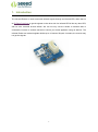
1. Introduction
The Infrared Emitter is used to transmit infrared signals through an infrared LED, while there is
an Infrared receiver to get the signals on the other side. An infrared LED is like any other LED,
with its color centered around 940nm. We can not only use the emitter to transmit data or
commands, but also to emulate remotes to control your home appliance using an Arduino. The
Infrared Emitter can transmit signals reliable up to 10 meters. Beyond 10 meters, the receiver may
not get the signals.
2
2. Specification
Voltage: 3.3-5V
Distance:10m
3
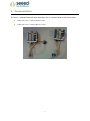
3. Demonstration
The Grove - Infrared Emitter can send data while Grove - Infrared Receiver will receive them.
Connect the Grove - Infrared Emitter to D3.
Connect the Grove - Infrared Receiver to D2.
4
4. With Arduino/Seeeduino
4.1
Suggest Reading for Starter
Download Arduino and install Arduino driver
Getting Started with Seeeduino/Arduino
4.2
IRSendRev Library
We have created a library to help you start playing quickly with the Seeeduino/Arduino, in this
section we'll show you how to set up the library.
4.2.1
Setup
1. Download the library code as a zip file from the IRSendRev github page.
2. Unzip the downloaded file into your …/arduino/libraries.
3. Rename the unzipped folder "IRSendRev"
4. Start the Arduino IDE (or restart if it is open).
4.3
Infrared Emitter Examples/Applications
These example are going to show you how to use features of Grove - Infrared Emitter. You can
use Infrared Emitter combination with Infrared Receiver Grove. Connect the IR send pins to
D3 for this demo.
4.3.1
Receiver
Notice: You need to have an Infrared Receiver Grove. And upload this demo to the board with
Infrared Receiver Grove
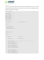
Open File->Examples->IRSendRev->example->recv sketch for a complete example, or copy and
paste code below to a new Arduino sketch.
Description
This example connect the IR receiver pins to D2 for this demo. You can see the remote control's
infrared data that received through a serial port terminal, then write the received infrared data into
send.ino and upload to the board with Infrared Emitter Grove, so you can send the same data with
remote control's button.
5
Application
You can note the remote control's infrared data down through Infrared Receiver, then send the
same data through Infrared Emitter in some cases, such as open the fan switch when indoor
temperature is greater than 26 degrees.
#include <IRSendRev.h>
#define BIT_LEN
0
#define BIT_START_H
1
#define BIT_START_L
2
#define BIT_DATA_H
3
#define BIT_DATA_L
4
#define BIT_DATA_LEN
5
#define BIT_DATA
6
const int pinRecv = 2;
// ir receiver connect to D2
void setup()
{
Serial.begin(115200);
IR.Init(pinRecv);
Serial.println("init over");
}
unsigned char dta[20];
void loop()
{
if(IR.IsDta())
// get IR data
{
IR.Recv(dta);
// receive data to dta
Serial.println("+------------------------------------------------------+");
Serial.print("LEN = ");
Serial.println(dta[BIT_LEN]);
Serial.print("START_H: ");
Serial.print(dta[BIT_START_H]);
Serial.print("\tSTART_L: ");
Serial.println(dta[BIT_START_L]);
Serial.print("DATA_H: ");
Serial.print(dta[BIT_DATA_H]);
Serial.print("\tDATA_L: ");
Serial.println(dta[BIT_DATA_L]);
6
Serial.print("\r\nDATA_LEN = ");
Serial.println(dta[BIT_DATA_LEN]);
Serial.print("DATA: ");
for(int i=0; i<dta[BIT_DATA_LEN]; i++)
{
Serial.print("0x");
Serial.print(dta[i+BIT_DATA], HEX);
Serial.print("\t");
}
Serial.println();
Serial.print("DATA: ");
for(int i=0; i<dta[BIT_DATA_LEN]; i++)
{
Serial.print(dta[i+BIT_DATA], DEC);
Serial.print("\t");
}
Serial.println();
Serial.println("+------------------------------------------------------+\r\n\r\n");
}
}
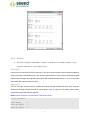
Upload the code to the development board.
Open the serial monitor window and wait for the input.
Using IR remote control sending data(This example use MIDEA Company's IR remote control of
fans, and press the open/close key.).
You can see the information below.
7
4.3.2
Emitter
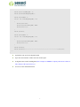
Open File->Examples->IRSendRev->example->send sketch for a complete example, or copy
and paste code below to a new Arduino sketch.
Description
Connect the IR send pins to D3 for this demo. You can see the remote control's infrared data that
received through Infrared Receiver, such as the example above. Then write the received infrared
data into this example and upload to the board with Infrared Emitter Grove, so you can send the
same data with remote control's button.
Application
You can note the remote control's infrared data down through Infrared Receiver, then send the
same data through Infrared Emitter in some cases, such as open the fan switch when indoor
temperature is greater than 26 degrees.
Notice: Must connect the IR send pins to D3 for this demo.
#include <IRSendRev.h>
#define BIT_LEN
0
#define BIT_START_H
1
#define BIT_START_L
2
8
#define BIT_DATA_H
3
#define BIT_DATA_L
4
#define BIT_DATA_LEN
5
#define BIT_DATA
6
const int ir_freq = 38;
// 38k
unsigned char dtaSend[20];
void dtaInit()
{
dtaSend[BIT_LEN]
= 11;
// all data that needs to be sent
dtaSend[BIT_START_H]
= 180;
dtaSend[BIT_START_L]
= 91;
// the logic low duration of "Start"
dtaSend[BIT_DATA_H]
= 11;
// the logic "long" duration in the communication
dtaSend[BIT_DATA_L]
= 33;
// the logic "short" duration in the communication
dtaSend[BIT_DATA_LEN]
= 6;
// Number of data which will sent. If the number is
// the logic high duration of "Start"
other, you should increase or reduce dtaSend[BIT_DATA+x].
dtaSend[BIT_DATA+0]
= 128;
dtaSend[BIT_DATA+1]
= 127;
dtaSend[BIT_DATA+2]
= 192;
dtaSend[BIT_DATA+3]
= 63;
dtaSend[BIT_DATA+4]
= 192;
dtaSend[BIT_DATA+5]
= 63;
// data that will sent
}
void setup()
{
dtaInit();
}
void loop()
{
IR.Send(dtaSend, 38);
delay(2000);
}
9
5. Resources
Grove-Infrared Emitter eagle files
IR Send and Receiver Library
TSAL6200 Datasheet
10