1
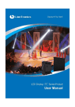
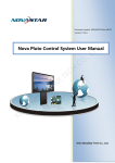
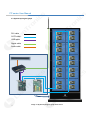
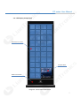
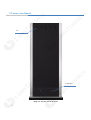
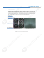
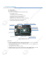
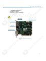
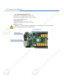
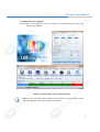
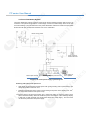
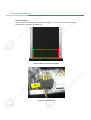
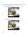
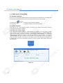
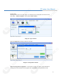
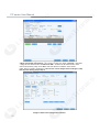
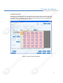
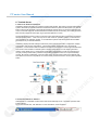
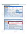
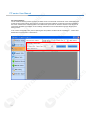
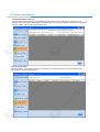
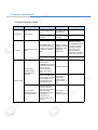
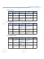
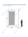
LED室内屏幕序列------高精度488X488压铸铝箱
PH 3.81
PH 5.08
PH6.09
PH 7.62
High Precision 488X488 Die-casting Aluminum Frame
PH 3.81 PH 5.08 PH6.09 PH 7.62
让公共视讯更完美!
PP series user manual
FOR MORE INFORMATION CALL:
www.liantronics.com
This manual is only for operating instructions and does not serve as repairing service.
Changes
Liantronics provides this manual ‘ as is ’ without warranty of any kind, either expressed or implied,
including but not limited to the implied warranties or merchantability and fitness for a particular
purpose. Liantronics may make improvements and/or changes to the product(s) and/or the
program(s) described in this publication at any time without notice.
This publication could contain technical inaccuracies or typographical errors. Changes are
periodically made to the information in this publication; these changes are incorporated in new
editions of this publication.
Copyright
All rights reserved. The copyright of this manual is protected by the Copyright Law of the People's
Republic of China and other intellectual property laws. No part of this document may be copied,
reproduced, distributed, translated, or used for commercial purposes. It shall not otherwise be
recorded, transmitted or stored in a retrieval system without the prior written consent of Liantronics.
LIANTRONICS CO., LTD
Add: Liantronics Building, No.1 Liuxian 3rd Road, Section 68,
Baoan District, Shenzhen, China
Postcode: 518101
E-mail: [email protected]; [email protected]
Visit us at the web: www.liantronics.com
PP series User Manual
Contents
1. Safety…………………………………………….…………………….……………..1
2. Installation Requirements…………………………………………………………3
2.1 Mechanical Requirements………………………………………………………………………….3
2.2 Electrical Requirements…………………………………………………………………………….4
3. System Introduction.………………………………………………………….……5
3.1
3.2
3.3
3.4
3.5
3.6
3.7
3.7
Brief Introduction……………………….…………..…………………………………....……..…...5
System Components…………………….………..…………………………………………..........5
System Topological Graph……....……….…………………………………………………….….6
LED Display Components.………...…….……………………………....…….………………......7
PP series Module…...……………………….……………………………………………………......9
Control System……………………..………………………………………………………….......10
LED System Control Software….....…………………………………....…….…………............13
Power Distribution System………...…………………………………....…….…………............14
4. Installation………………………………………………………….…………..15
5. Start-up of the System……………………………………………………….…...18
5.1 Software Installation……..……………………………………………………………………...18
5.2 System Operation…………………………………………………………………………………..18
6. Trouble Shooting………………………………………………………………….22
6.1 Nebula Software Installation..…………….……………………………………………………….22
6.2 Install The Nebula TC Software.…………………………………………………………………22
6.3 Main Interface Of Nebula TC.…………………………………………………………………….23
6.4 Screen Configuration………….…………………………………………………………………...23
6.5 Camera Setting…………….....….……..…………………………………………………………..24
6.6 Basic Information Of The Terminal……………………………....…………………………….....25
6. 7 Sof tware Update Inf ormat ion………… …… ……… …… …… …… …… …… …. . … . . . . … …… . . . . . 25
6.8 Download Status Of The List……………………………………………………....……………...26
6.9 Log Upload Status..………………………..………....………………………………………..…..26
7. Trouble Shooting………………………………………………………………….25
7.1
7.2
7.3
7.4
7.5
Software Trouble……………..…………………………………………………………………….25
Hardware Trouble…… …..…...……… ……………… … …… …… … …… …… … …… …… … …2 6
Module Problems……..…… ...… …………… …………… ………… … …… …… … …… … …… .29
Power Problems……….…………………………………………………………………………...29
Data Transfer Probl em s… …..… … …..… …… …… …… … …… …… …… … …… …… …… … ..29
8. Maintenance.………………………………………………………………………..30
Appendix A. Technical Specification.…………………………………………….31
Appendix B. Dimensions.…………………………………………………………...32
PP series User Manual
1. SAFETY
This chapter contains important information to prevent personal injury and product damage when
you install the display. Read this chapter and keep it properly. Ensure that you understand and
follow all the safety instructions and warnings in this chapter before installing.
Personal Protection
Warning: Ensure that you understand and follow all the safety instructions,
warnings mentioned in this manual.
Warning: Pay attention to electric shock.
Warning: Wear a hard hat to reduce the risk of personal injury.
Warning: Be aware of suspended loads.
Warning: Mind your fingers while dealing with heavy loads.
Personnel of installation and maintenance
The installation and maintenance of this product must be performed by authorized and qualified
technical personnel only. The manufacture does not take responsibility for the results caused by
incorrect, improper, irresponsible and unsafe actions.
GND and Lightning protection
Do not underestimate the safety protection of grounding plug/socket. If the supplied plug/socket is
defective, replace the defective parts. Ground the product correctly to avoid electric shock
caused by large electricity leakage.
Disconnect the power in the time of lightning, or provide other suitable lightning protection device.
Disconnect the power plug when the product is not used in a long period.
Ambience of installation and use
•
The ambient temperature for LED display: max 40°C, min 0°C.
•
Ensure that the ventilation is good. Do not jam or drop metal particles and cable pieces into
ventilation opening. Keep the ventilation surface clear without foreign matters like wrapping
materials. False actions may lead to poor ventilation and cause fire, malfunction and error.
•
Install LED display far away from radiator, heater, furnace and other equipments hindering
ventilation and heat dissipation (including but not limited to amplifier, laser, ultrasonic vibration
devices), flammable materials (like curtains) and other unsafe devices.
•
I/O signal cables should be shielded to restrain the high-frequency interference.
•
LED display can not contact with any corrosive and abrasive matter. Do not use LED display in
moist ambience, in ambience containing airborne contaminant, dust, oily fume, corrosive gas and
flammable gas, and in ambience with vibration and shock.
•
This LED indoor product is designed only for indoor use. Never install and use it in outdoor
environment and keep it far away from direct sunlight, dust and moisture.
www.liantronics.com
1
PP series User Manual
ESD and LED:
LED components are ESD (Electro-static Discharge) sensitive. Do not touch LED components when
the display is in operation or switched off.
Disconnect device:
When the appliance inlets of the individual tiles are not accessible, the socket outlets supplying the
rack shall be installed near the equipment and be easily accessible, or a readily accessible
general disconnect device shall be incorporated in the fixed wiring.
Mounting parts:
The mounting parts are only used to install LED display. Do not repair or copy. Only use parts
appointed by the manufacturer. Contact LIANTRONICS if you want customized application.
Product care:
Inspect all installations on a routine basis to check security, wear, deformation, corrosion or any
other situation that reduces load-carrying capability. Increase inspection frequency for key parts.
Keep structural and mounting parts dry, clean, lubricated (only if recommended), coated
properly, and maintain complying with part design. Defective parts must be removed or replaced
at once.
Installation and wiring:
Install the display and connect cables following the manual instructions. The installation and wiring
must be secure. Poor connection may lead to malfunction. Do not step on power/data cable or
squeeze plug, socket and power/data cable. Do not suspend any items on cables or the back of
LED display. Connect or disconnect the cables of data communication, extension module or
control unit after the power is off to prevent product damage or malfunction.
Risk of electric shock:
•
To avoid electric shock and damage , do not dismantle the inside electrical parts.
•
Hot plugging the cable is forbidden to prevent electric shock or circuit damage.
•
Keep clean after installing and cabling. Be ensure all the devices and terminals are covered
before turning on the power.
•
Do not touch the terminals when power is on. Clean and screw the terminals when power is off.
Moving or transporting product:
Do not hit the corners of LED tiles when installing or dismantling LED tiles. Be careful when moving
or transporting the product to prevent any damage.
LED tiles can not be transported in containers other than LIANTRONICS flight cases or packaging.
Even the use of LIANTRONICS packaging does not guarantee the LED tiles against damage
due to excessive force of impacts. All warranty claimed regarding damaged modules due to
incorrect packing will be rendered invalid.
2
PP series User Manual
2. Installation requirements
This chapter specifies the requirements for safety, mechanism, electricity and control software of PP
series.
Warning: This LED indoor product is designed only for indoor use. Never install and use it
in outdoor environment and keep it far away from direct sunlight, dust and moisture.
2.1 Mechanical Requirements
Weight
Warning: Do not underestimate the weight of the PP series. Be sure that the floor or
truss installation on which the PP series has to be installed is capable of handling five (5)
times the complete load of the display. For floor mounting, conclude the weight of any
other load.
Horizontal surface
For floor installation, the floor on which PP series is installed must be horizontal. Never install LED
display on a slant surface.
Ballast
Depending on the height of the display and the position of the LED display upon the foot beams
(somewhere between front and middle) , additional weight (ballast) will be required. Consult
professionals of LIANTRONICS to calculate the minimum ballast you require for safe
installation of the LED display.
Installation ambience
•
Environmental conditions: humidity, ventilation, temperature, etc.
•
Location: Altitude, etc.
•
Front clearances: for optimal effect, ensure that enough free space is
supplied in front of the LED display and respect the minimum viewing distance.
•
Comply with local regulations regarding such installations.
3
PP series User Manual
2.2 Electrical Requirements
Power requirements
Electrical parameter
Input voltage
220±15% (According to the actual situation )
Average power
consumption
815W
Max power consumption
2450W
Input power frequency
50/60Hz
Max supply current
11.1A
AC/DC Power supply
electrical specification
Input voltage: 220±15%
Output voltage: 57.6VDC
Output current: 0~50A
AC/DC Power supply
electrical specification
Input voltage: 36VDC~76VDC
Output voltage: 5VDC
Output current: 0~30A
Power cable standard
3 X 2.5mm2
Power system
It is recommended to use power distribution system with a separate neutral and grounding
conductor to avoid large current loops due to voltage differences in the neutral conductor.
•
Protect the electrical installation by switch, circuit breaker, over-voltage protector, defectivegrounding circuit breaker with proper rated power.
•
Install the display in accordance with local electrical installation standards. In Europe, comply
with EN 60364, the standard for electrical installation of buildings. In Germany, comply with EN
60364. In America, comply with National Electrical Code ANSI/NFPA 70.
Protective grounding
To prevent against the risk of electric shock, the installation should be properly grounded. Defeating
the purpose of grounding will expose you to the risk of electric shock.
4
PP series User Manual
3. System Introduction
3.1 Brief Introduction
PP series of Liantronics, the super-size LED digital signage, defines an electronic totem in digital
times. As the combination of hi-tech and artistic creation, it combines information transmission,
artistic expression and time connotation as one.
3.1.1 Key Benefits
•
Super durable design
•
High grade protection with tempered glass
•
Hot backup system
•
Double backup power supply
•
Remote control and monitoring system
•
Centralized cluster network and remote control system to monitor and manage the status of
LED screen
•
Embedded with video monitor and ammeter
•
Access for WiFi/3G wireless and wired network
•
4.1 sound track output
3.1.2 Applications
PP seriess are perfect for airport, subway station, train station, large shopping mall, star grade hotel,
book store, pavilion, conference center, cinema, bank, office, etc.
3.2 System Components
PP series series includes the following basic components:
•
LED Display: PP series
•
Control System: control computer, LED display controller, distributor, control system software
5
PP series User Manual
3.3 System topological graph
DVI cable
CAT5 cable
USB cable
Signal cable
Audio cable
6
Image 3-1 System topological graph of PP series
PP series User Manual
3.4 LED Display Components
LED module X 40 PCS
Tempered Glass
Metallic Painted Base
Image 3-2 The front face of PP series
7
PP series User Manual
Fan
Access panel
Image 3-3 The back face of PP series
8
PP series User Manual
3.5 PP series Module
PP series module includes die-casting aluminum base frame, PCBA, etc. At the back of the
die-casting aluminum base frame, two copper screw holes are inlaid at each side to fix the
module to the frame. The black LED lamp array lies in front of PCBA. LIANTRONICS adopts
the black full color SMD LED lamps. The use of black organic silicone and diffuser makes the
black LED lamps darker to improve the contrast of the display significantly.
+5V input port
Signal input socket
+5V input port
Signal input socket
Die-casting Aluminum
base frame
Back side of the LED module
Front side of the LED module
Image 3-4 The components of P3 module
9
PP series User Manual
3.6 Control system
3.6.1 LED Receiver Card
The functions of the MRV300 receiver card are shown as below:
•Power supply: 3.3 - 5.0V
•Temperature monitoring (standard feature)
•Power supply voltage monitoring (standard feature)
•Working status monitoring (standard feature)
•16 RGB data groups output (it can be extended to 32 groups.)
•Load capacity of single receiver card up to 256×128
•Support pixel level brightness/color calibration
DC input socket
Press this button to change test pattern
DC input terminal
50 pins data interface A
RJ45 interface A
Extension data interface
RJ45 interface B
Status monitor Interface
Reserved interface
50 pins data interface B
Image 3-5 MRV300 receiver card
Off-line Test
The receiver card supports off-line test. Users can test each parts of the PP series without
connecting with LED control system. The test steps are as below:
10
1.
Make sure that the receiver cards are connected with each of the LED modules but not
connected with CAT5 data cable.
2.
Turn on the LED screen, the tiles show nothing.
3.
Press the black switch on the receiver card seven times. Then the display contents on the LED
tile will be changed to Diagonal, Grey, Red, Green, Blue, White and Black in order.
PP series User Manual
3.6.2 MSD300 Transmitter Card
1.DVI interface for video input
2.USB interface for instruction communication
3.Audio input interface
4.Resolutions supported:1024*1200, 1280*1024, 1600*848, 1920*712, 2048*640
Caution: A multifunction card is required for outputting the audio.
Data Interface A
3.2V~5.0V input socket
Data interface B
USB interface
DVI input interface
Image 3-6 MSD300 transmitter card
11
PP series User Manual
3.6.3 MFN300 Multifunctional Card
1.RJ45 ports for connection with receiver cards
2.serial ports for connection with the control computer
3.Support 8 power supply control
4.Support light sensors
5.Support temperature and humidity monitoring
6.Audio input interface
Caution: For audio output, the multifunctional card needs to be connected between
receiver cards or at the end of the cascading chain.
3.2V~5.0V input socket
Rs232 Serial port
RJ45 connect to receiver card
Image 3-7 MFN300 multifunctional card
12
PP series User Manual
3.7 LED System Control Software
NovaLCT-Mars control software is used to configure and control LED display through PC in
Graphics User Interface.
Image 3-8 NovaLCT-Mars control software interface
Note: For more information about installation and instruction of control software, consult
Nova LED Display Control System –Mars 3 User Manual.
13
PP series User Manual
3.8 Power Distribution System
The power distribution system of the PP series has air switch, leakage protection switch, fuses, AC
contactors. The system has protection of overvoltage, overcurrent, undervoltage, short circuit, open
circuit and leakage. The main switches in the power distribution cabinet are made of the Schneider
devices and all other accessories and wires has "CCC" certification.
Electric energy meter
SSR
Power supply for
Multi-funtion card
Filter
Positive pole terminal
Negative pole terminal
Power supply for
IPC & Speaker
Image 3-9 PP series power supply system diagram
Selecting and layout of the power line
•
LED display is supplied with AC220V power with good grounding and requires that the grid
voltage fluctuation is less than 10%.
•
Determine the diameter of the power cord according to the power of the display (Unit: mm2,
the cross-sectional area of the power cord).
The power supply has three-wire system (live, neutral and earth) or five-wire system (3 live
wires, neutral and earth). When the maximum power consumption of the LED large-display
is less than 10 KW, generally use single-phase three-wire power supply , and vice versa
use the three-phase five-wire power supply.
14
PP series User Manual
4. INSTALLaTION
Installation Preparation
Good viewing angle and good sight for the surroundings
•Favorable ventilation conditions
•Safe and stable rating input voltage
•Suitable size, firm and stable installation table-board
•Rear maintenance space is more than 800mm from front to back.
Tools list for installation (choice depends on the practical jobsite)
1. Diagonal cutting plier
Cut the wire
2. Combination plier
3. Screw drivers
Cut the steel wire rope
Install tiles and power supply
4. L shape spanners
5. End wrench tool set
6. Adjustable wrench
Tighten or loosen the screw
Tighten or loosen the screw
7. Socket wrench
8. Digital multi-meter
9. Rubber hammer
Assemble the screen
Measure voltage or current
Adjust the gap between tiles
Install tiles
Other tools for installation (choice depends on the practical jobsite)
Electric drill
Tools
Quantity
1pc
Function
Drill holes on the wall or frame
Rivet drill
1pc
Fix the cabinet in place
Electric adhesive plaster
Several
Isolate electricity after wire is connected
Tape measure
1pc
High-brightness flashlight
1pc
Used in the dark area
Safety rope
Ref.
Personal safety, very important
220V power outlet board
1pc
Power supply
Level & vertical ruler
1pc
Test the level of the frame
15
PP series User Manual
Power connection
Open the back shroud which is showed in the Image 4-1. Then you can find the Terminal
blocks which is showed in the Image 4-2.
Image 4-1 Back shroud of the PP series
Image 4-2 Terminal blocks
16
PP series User Manual
If your local power voltage is 220V, you should connect the input power cable like Image4-3.
The power voltage between L and N is 220V.
220V INPUT:
G
N
L
Image 4-3 Power connection of 220V power input
If your local power voltage is 110V, you should connect the input power cable like Image4-4.
The power voltage between L1 and L2 is almost 190V.
110V INPUT:
G
L2
L1
Image 4-4 Power connection of 110V power input
17
PP series User Manual
5. START-UP OF THE SYSTEM
5.1 Software Installation
Before you run the software, please make sure all connection are ready (From PC to sending card,
from sending card to LED screen). Put the LED system installation CD into CD-ROM.
1.Double click
to start LED control software installation.
2.Follow the installation instruction until the installation procedure has finished.
5.2 System Operation
First, power on the control system computer, and switch on the power of LED display. follow the
procedures and instructions as below :
1.Start Nova LCT control software
Install “ Nova LCT control software ” , double click the icon (image 5-1) to open Nova LCT Mars
control software, and the computer will enter to the interface as image 5-2. “ Local system info ”
shows the real system connection information. when it shows “ Control System: 1 ” , it means the
USB serial port connection is ready for communication between PC and controller . If not it shows
“Control System: 0”for the connection is not good with no communication. If there is no image on
LED screen (green indicator of sending card not flicking), please check DVI cable from graphic card
to sending card, then check multi-display mode from control computer. Keep display mode under
duplicate mode.
Image 5-1
Image 5-2
18
PP series User Manual
2. User Login
User login—This menu is for user to login. It is necessary for the configuration of the LED screen.
Click “User”,--“Advanced Log-in”, enter password”666”or”admin”.
Image 5-3 Login interface
Select “Config Screen” directly to follow the next step:
Image 5-4 Configuration interface
3.Go to sending board configuration: As is Shown in image 5-5, select proper resolution for
sending card, and it should be close to graphic card. Click “Save” to save parameter on HW.
19
PP series User Manual
Image 5-5 Sending board configuration interface
4.Go to scan board configuration:As is shown in image 5-6, select “Load File”, down load
“*.rcfg” file from delivered CD. Click “Send To HW ”, and then the file will be send to each
scan board (receiving card). Click “Save” and save all files in hardware, when restart
power ,files is no need to send again. If tiles shows correct images before loading file, skip
this step and directly jump to step 5.
Image 5-6 Scan board configuration interface
20
PP series User Manual
5. Screen connection
According to the data cabling of your LED Display, fill in the actual value of columns and rows.
Choose right ports and fill right scan board size as below. Select correct direction of signal cable
cascading. Image 5-7 shows the front view of screen (see from image4-6) “S” for the first tile and “E”
for the last one. Choose “Send to HW” and “Save”.
Image 5-7 Screen connection interface
21
PP series User Manual
6. Terminal Server
6.1 Nebula TC Software Instruction
Advertising display terminal is an unmanned multi-media system. After being connected with Nebula
system, terminals can realize information transmission with the system and the system can offer all
kinds of services for terminals. Terminals will periodically visit the server to receive and perform the
control command: terminals will download and broadcast the list /do the listing, and collect and feed
back execution result as well as play log for operation platform to check.
Several tips shall be noted in order to make the system automatically start up and enter into Nebula
terminal working state: 1. There can only be one user name for operation system; 2. There should
not be password for operation system; 3. The Windows7 system shall set the terminal executable
permissions only for the administrator.
Advertising display terminal settings include three parts: terminal information configuration, display
configuration and camera configuration. Terminal information configuration is to set terminal
registration, communication rules and relative information to the server to ensure right authentication
and normal communication in Nebula system. Display configuration is to set mapping area and
location of the display in IPC, and program broadcasting configuration to make sure that terminal
can play correctly and smoothly. Camera configuration provides a means of on-spot and desktop
monitor. By camera configuration, users can take photos and get screen shots of the desktop and
send them to the server. The platform can monitor these photos and shots to know system operation
status.
Operation platform
Service platform
6.2 Install the Nebula TC Software
After Nebula TC is installed, terminal server will be automatically set as “ automatic operation after
system startup”.
If you need manual start, click Nebula TC in the Start Menu, shown as below:
22
PP series User Manual
6.3 Main interface of Nebula TC
:
6.4 Screen Configuration
Fill in the blank according to the actual size and mapping area of the display in order to play the contents
accurately and completely.
23
PP series User Manual
6.5 Camera Settings
On-site visible monitoring solution would be provided, which is involved with screenshots of the multimedia player
as well as timing photo-taking of the camera. Through the operation platform, the pictures which are uploaded to
the server could be seen and downloaded. The maintenance personnel can know the situation of the screen via
screenshots. Besides, the condition of surroundings and audience can be detected through the camera phototaking process.
In the camera configuration bar, picture-capturing size and position could be set via sub-dialogue--- camera shot.
Remember to tick and select “camera shot".
24
PP series User Manual
6.6 Basic Information of the Terminal
Basic information of the terminal mainly indicates the current status of the terminal. For instance, the MAC
address, equip connect status, read equip status result, interaction interval, last interaction time and result.
See the picture below:
6.7 Software Update Information
This part maintains the current version of terminal and the update status of terminal version, as shown in the
following picture:
25
PP series User Manual
6.8 Download Status of the List
Terminal of the advertising display would download the list from the server and play it in accordance to its
schedule. After receiving the download list or schedule order, the terminal would start to download, and the whole
progress together with the result can be clearly seen .
6.9 Log Upload Status
When the platform commands the terminal to upload play log, the upload progress and result would be fully
demonstrated. See the following picture:
26
PP series User Manual
7. Trouble Shooting
7.1 Software Trouble
Problem
type
Problem description
Unable to open
NovaLCT
System notice:
NovaLCT.exe-error
LCT system
connection fails
Nova LCT
display brightness is
not uniform
LCT software monitor
shows wrong status
One area of receiver
card is black
Nova Studio
The whole display is
black
Solution
Reason
Analysis
Replace LCT software Software problem
Install Microsoft .NET
Framework 2.0
Check the RS-232
connection and
communication
Computer is not
installed
wit
h .NET Framework
software
The RS-232
communication is not
connected or could
not get through
1.Computer is not
installed with .NET
Framework
2. Already installed, but
may be damaged
Nova LCT version may be
changed, confirm that you
use the right version.
Replace LCT
LCT communication
is not stable
Set values of R, G, B
brightness on the all
controllers as the
same
1. Brightness values are
Controller's R,G,B
not the same.
brightness values are
2. Data is not saved
not the same
successfully after setting.
The calibration mode
of controllers did not
set to “On”.
1. Calibration mode is not
“On”.
2.All the calibration
modes are “On”, but not
successfully saved after
setting
The brightness is
different before and
after calibration
Brightness adjusting
Change the brightness modes are different
adjusting mode
between different
controllers
Check Gamma value
of different controllers
and resend the
database
Gamma values are
varied for different
controllers
If brightness adjusting
is in auto mode and
controlled by sensor,
new update needs to
wait for 30 seconds
Brightness sensor
action need to wait
for 30 seconds.
Change and re-install
LCT software
Check the row and
column setting in LCT
Close the play time
schedule
Check the media
source
1. Brightness adjusting
modes are not set as the
same
2.The setting is not saved
successfully
Software problem
Map setting in the
LCT is wrong
Time schedule
setting is wrong
Media source is lost
or stopped
27
PP series User Manual
7.2 System Hardware Trouble
Problem type Problem description
Controller
Black screen
Solution
Reason
No HDMI signal output
from the graphics card
in PC
No HDMI signal to
the controller
Check the power of the
controller
No power for the
controller
Analysis
Re-start the controller
Divider
Divider is working
when RUN lamp blinks
There is no data
Check RUN status on
2 times per second.
the divider. If it blinks 2 from the controller
The lamp blinking 2
seconds once, it means or the fiber cable
seconds per time
Divider driving area is no data from the fiber
is not well
means no data is
black
connected
cable.
output from controller
or the fiber is broken
Check the power of the
divider
Receiver card
problem causes
black display on
single tile
Receiver card
One row of the
module in the tile is
black or messed up
28
No power for the
divider
Check data input from
upper receiver
card(RUN lamp blinks 2
times per second). If the
Hardware problem
data in is ok but
problem still exists,
replace the receiver
card
If there is no data input
from the cat5, check the
cat5 connection or no
data output from the
upper receiver card
Poor Cat5
connection or
output data
problem of the
upper receiver
card
Check the hub card
connection with the
scan card, or the ribbon
cable connection
Connection
between the hub card
problem or
and module. If
hardware problem
connection is no
problem, replace the
hub card
PP series User Manual
7.3 Module Problems
Problem
type
Problem
description
Phenomenon &
Solution
Reason
Analysis
The lamp is dead or
soldering is not good
LED lamp
Blind lamps
Replace the module
LED pixel
The pixel area is
black or loses color
The driving IC/resistor is
Replace the module bad soldered or out of
work
LED module
One or several
whole LED modules
in the same row are
black or defective
Check the ribbon
Cable is not connected
cable and power
cable connection on or not well connected
the module
7.4 Power Problems
Problem
type
Problem
description
Phenomenon &
Solution
Reason
Tile power
The whole tile is
black
Check power
connection with the
tile and the breaker
in the tile
Power to the tile is not
well or the breaker is
turned off
Power supply
The whole tile is
black
Replace the
defective power
supply
The power supply
feeding the receiver
card is defective
Replace the
defective power
supply
The power supply
feeding the module area
is defective
Several nearby
Power supply module areas are
black
Analysis
7.5 Data Transfer Problems
Problem type
Problem
description
Phenomenon &
Solution
Reason
Cat 5
Check the data
The whole column
The connection is not
connection between
of the display is
good or the cat5 is
the divider and the
black
defective
first scan card
Cat 5
One or several
tiles in column are
black
Cat 5
All the display light
Check and correct
up but the columns
The connection order is
the Cat5 connection
are not in right
wrong
order in the divider
order
Analysis
Check the cat5
The connection is not
connection between good or the cat5 is
the tiles
defective
29
PP series User Manual
8
Maintenance
Routine maintenance
1.
Make sure the LED display is well ventilated, dry and running in suitable temperature.
2.
Regularly check the internal cables inside the LED display are in stable connection, the power
supplies are working well, the ground wires are connected well, and the lightning arrester is
running well.
3.
Regularly wipe the dust on the surface of the LED tile with a soft cloth, and keep the LED
display surface clean to avoid brightness differences between clean and unclean LED tiles.
Cautions for use
30
1.
Before power on the LED display, start your computer first, and then turn on the power of LED
display.
2.
Before turn off the display system, first turn off the power of LED display, and then turn off the
computer.
3.
When you are editing video playlist, you had better to keep the LED display off.
4.
When failure appears, first turn off the power of LED display, then contact with service
department of LIANTRONICS for technical support.
PP series User Manual
Appendix A: Technical Specification
Item
PP series
Pixel Pitch (mm)
3
2.4
Screen Size
122’’ diagonal
97’’ diagonal
Dimensions
1412mm(L)X3486mm(H)X120mm(D)
1112mm(L)X2758mm(H)X120mm(D)
Display Size
1152mm(L)X2880mm(H)
952.32mm(L)X2261.76(H)
Resolution
384pixels(L)X960pixels(H)
384pixels(L)X912pixels(H)
Weight
200Kg
190Kg
Power Consumption
750W (Average) / 2400W (Max)
600W (Average) / 2000W (Max)
Brightness
1200cd/m 2
Viewing Angle
H: 160o / V:160o
Contrast Ratio
3000:1
Refresh Rate
≥1920Hz
Frame Rate
60Hz
Color Temperature
2000K≤TC≤9300K (Adjustable)
Brightness Adjustment
Programmable/ Auto/ Manual
Signal Processing
16bit
Communication
WiFi/ 3G/ CAT 5
Protection Grade
IP32
Life Span
50,000hrs
Power Supply Voltage
176-264V(AC)
Operation Temperature
-20o ~ +50o
Storage Temperature
-40o ~ +60o
Relative Humidity
10% ~ 95%
Moisture-proof, dust-proof, flame retardant
Protection
Anti-corrosion, anti-static, anti-seismic
High temperature & lightning protection
Over current or short circuit protection
Safety
Over voltage or low voltage protection
Temperature alarm
Failure Monitoring
Monitoring of temperature, voltage, working condition, network failure
31
PP series User Manual
Appendix B: Dimensions
32
PP series User Manual
33


![English-T series-NOVA-User manual-F [兼容模式]](http://vs1.manualzilla.com/store/data/005791006_1-acba31ea472695c25db426bea2198a0f-150x150.png)