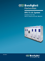
1
RPS TL-UL System
Solutions for the
North American Solar Market
2015/2016
Power, control
and green solutions
3
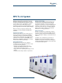
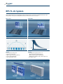
RPS TL-UL System
With the new generation of the RPS TL-UL series,
Bonfiglioli expands its product range of solar PV
inverters for the North American market, reaching
a power rating of up to 1,575 kWac for a single
inverter system. The modular design ensures
maximum energy harvest, optimal adaptation to PV
plant configurations and excellent system reliability.
RPS TL-UL inverters carry the ETL mark for full
compliance to UL1741, IEEE1547 and IEEE1547.1
standards.
Flexibility and Scalability
The RPS TL-UL boasts one of the widest ranges of
inverter ratings in the market (from 376 kWac to
1575 kWac), ensuring an optimal matching with
every PV array configuration. The scalable modular
architecture offers options for Multi-MPPT and
Master-Slave configuration, which help to manage
workload and maximize productivity.
Advanced Grid Features
Bonfiglioli RPS TL-UL inverters are designed
according to the most stringent grid codes in order
to offer the following features:
• Complete set of advanced grid features set
including LVRT, HVRT, FRT, ramp rates, reactive
power control, power factor control
• Large power factor capability (0.9 lead/lag at rated
power)
• Compliant with all major utilities’ requirements.
RPS TL-UL from 376 kWac to 1575 kWac
Quality and Availability
The RPS TL-UL is a uniquely-designed high-power
solar PV inverter system that provides maximum
energy harvest. Thanks to the rigorous modular
architecture, the RPS TL-UL ensures maximum system
reliability: a single fault in an inverter module will
never affect more than only one subfield, while the
balance of the system continues to operate with
minimum loss of energy production.
Reliable Partnership
Thanks to over 25 years of engineering excellence
in power conversion technology, Bonfiglioli has the
required footprint, experience and infrastructure to
develop and deliver complete, cost-effective inverter
solutions.
In addition, the overall business composition of
Bonfiglioli ensures financial stability to support
installations long-term, and to provide and support
customers with uptime guarantees and a wide range
of extended warranty options.
5
RPS TL-UL System
The scalable, modular architecture of the RPS TL-UL
offers greater system flexibility and more options
for managing working load, making Bonfiglioli an
ideal partner for large commercial and utility-scale
installations.
Available in Master-Slave or Multi-MPPT
configurations, the RPS TL-UL system includes
floating or grounded arrays up to 1000 Vdc.
Master-Slave Configuration
The Master-Slave configuration intelligently
manages the working load of each module in order
to maximize conversion efficiency and provide an
extended working life. The automatic disconnection
of individual modules during fault conditions ensures
a minimal effect on the energy production by
allowing the rest of the system to operate normally.
The Master-Slave system is ideally suited to provide
the most benefit in efficiency under partial load
conditions and will allow the system to start earlier
in the morning and stop later in the evening.
Multi-MPPT Configuration
The Multi-MPPT configuration provides independent
control for multiple sub-arrays, making this
configuration ideally suited for solar applications
with different irradiance profiles, mismatched
solar panels or multiple surface slopes. In this
configuration, the system is able to minimize the
solar array mismatch losses by actively searching for
the best operating point which maximizes power
production. This system also enables applications
with different electrical characteristics to be used
together, which maximizes efficiency and increases
productivity.
Comprehensive Grid Management
• Anti-islanding with grid voltage and frequency
protection according to UL1741 & IEEE1547
• Extensive set of advanced grid features, including
LVRT, HVRT, FRT, ramp rates, reactive power control
and power factor control (for more details on grid
management, see page 13).
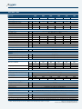
Technical Overview
• Wide range of inverter power ratings from
376 kWac to 1,575 kWac
• Modular inverter system with up to 7 independent
MPPT inputs
• ETL certified to UL1741, IEEE 1547 and IEEE 1547.1
standards
• Full suite of power management functions
• DC breaker provided for each module to provide
disconnection from the solar array
• Includes main AC breaker to provide overall
protection for inverter lineup
• Suitable for floating or grounded (positive or
negative) array configurations.
Bonfiglioli has established the assets, competence,
and technical prowess to successfully deliver and
install commercial and utility-scale power systems
anywhere in the world.
SELECTED WORLDWIDE REFERENCES
70 MW Rovigo, Italy
50 MW Puertollano, Spain
60 MW Karadzhalovo, Bulgaria
200 MW Golmud, China
90 MW Gujarat, India
100 MW, Atacama, Chile
170 MW California, USA
6
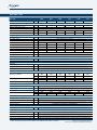
Multi-MPPT - 360V
RPS TL-UL
0400
0600
0800
1000
1200
1400
-
2
3
4
5
6
7
Maximum input current
A
700
1050
1400
1750
2100
2450
Maximum DC input voltage
V
MPPT range
V
Number of MPPT trackers
-
2
3
4
5
6
7
Number of DC inputs
-
4
6
8
10
12
14
Number of inverter modules / cabinets
Input ratings
1000
550 ... 850
Output ratings
AC voltage
V
360 (IT mains, floating neutral or ungrounded delta)
AC voltage range
V
317 - 396 (-12 % to + 10 %)
Frequency range
Hz
Rated power @ 0.9pf
kW
376
564
752
940
1128
1316
Maximum active power
kW
400
600
800
1000
1200
1400
Maximum apparent power
kVA
424
636
848
1060
1272
1484
Rated output current
A
640
960
1280
1600
1920
2240
Maximum output current
A
680
1020
1360
1700
2040
2380
Power factor range
-
controllable 0.8i ... 0.8c (nominal > 0.99 at rated power)
%
< 3 at rated power
Current harmonic distortion
59.5 - 60.5
Auxiliary power
External power (single phase)
-
Standby power consumption
W
240 V / 10 A
40
60
80
100
120
140
Efficiency
Maximum efficiency
%
98.6 (prelim)
European weighted efficiency
%
98.4 (prelim)
CEC weighted efficiency
%
98.0 (prelim)
Mechanical details
Dimensions (WxHxD)
Weight (approx.)
Protection class
mm
1800x2100x
800
2400x2100x
800
3000x2100x
800
3800x2100x
800
4400x2100x
800
5000x2100x
800
in
71x83x31.5
95x83x31.5
118x83x31.5
150x83x31.5
173x83x31.5
197x83x31.5
kg
1300
1850
2450
3000
3550
4100
Ibs
2860
4070
5390
6600
7810
9020
-
Nema1 / IP20 (Indoor only)
-
-4°F … 131°F ('-20°C ... +55°C)*
Temperature
Ambient operating temperature range
Rel. humidity
%
up to 95 (not condensing)
Max. altitude
m
13123 ft / (derating above 3280 ft) / 4000 m (derating above 1000 m)
Req. air flow rate
m3/h
3000
4500
6000
7500
9000
10500
cfm
1766
2649
3532
4415
5298
6181
Protection and monitoring
Array grounding configuration
-
Floating
Array ground fault protection
-
Impedance Monitoring
Grid protection
-
Anti-Islanding / Adjustable voltage and frequency settings according to IEEE1547
Surge protection
-
UL1449, Class II on DC Input and AC Output
-
RS-485 (ModBus® / RTU or proprietary), Options: ModBus® / TCP over Ethernet
Interfaces
Communication interface
Standards & certifications
Standards
-
UL1741 / CSA107.1 / IEEE1547, UL1998, NEC2014
Testing
-
IEEE1547.1 / IEEE C62.41.2 / IEEE C62.45 / IEEE C37.90.1 / IEEE C37.90.2
Environmental conditions
-
EN 60721-3-3 (3K3, 3B1, 3C1, 3S2, 3M1) (unless deviating specifications provided)
Supported Power Management Functions
-
LVRT, Power Factor Control, Grid Fault Support, Power / Frequency Control and Ramp Rate
* -10°C…+45°C at rated power for Vdc < 700 V, lower minimum temperatures on request
Subject to change without notice.
Refer to user manual for detailed specification.
7
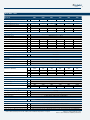
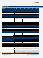
Multi-MPPT - 386V
RPS TL-UL
0425
0640
0855
1065
1280
1495
-
2
3
4
5
6
7
Maximum input current
A
700
1050
1400
1750
2100
2450
Maximum DC input voltage
V
MPPT range
V
Number of MPPT trackers
-
2
3
4
5
6
7
Number of DC inputs
-
4
6
8
10
12
14
Number of inverter modules / cabinets
Input ratings
1000
575 ... 850
Output ratings
AC voltage
V
386 (IT mains, floating neutral or ungrounded delta)
AC voltage range
V
340 - 425 (-12 % to + 10 %)
Frequency range
Hz
Rated power @ 0.9pf
kW
400
600
800
1000
1200
1400
Maximum active power
kW
427
641
855
1069
1283
1497
Maximum apparent power
kVA
454
681
909
1136
1363
1591
Rated output current
A
640
960
1280
1600
1920
2240
Maximum output current
A
680
1020
1360
1700
2040
2380
Power factor range
-
controllable 0.8i ... 0.8c (nominal > 0.99 at rated power)
%
< 3 at rated power
Current harmonic distortion
59.5 - 60.5
Auxiliary power
External power (single phase)
-
Standby power consumption
W
240 V / 10 A
40
60
80
100
120
140
Efficiency
Maximum efficiency
%
98.6 (prelim)
European weighted efficiency
%
98.4 (prelim)
CEC weighted efficiency
%
98.0 (prelim)
Mechanical details
Dimensions (WxHxD)
Weight (approx.)
Protection class
mm
1800x2100x
800
2400x2100x
800
3000x2100x
800
3800x2100x
800
4400x2100x
800
5000x2100x
800
in
71x83x31.5
95x83x31.5
118x83x31.5
150x83x31.5
173x83x31.5
197x83x31.5
kg
1300
1850
2450
3000
3550
4100
Ibs
2860
4070
5390
6600
7810
9020
-
Nema1 / IP20 (Indoor only)
-
-4°F … 131°F ('-20°C ... +55°C)*
Temperature
Ambient operating temperature range
Rel. humidity
%
up to 95 (not condensing)
Max. altitude
m
13123 ft / (derating above 3280 ft) / 4000 m (derating above 1000 m)
Req. air flow rate
m3/h
3000
4500
6000
7500
9000
10500
cfm
1766
2649
3532
4415
5298
6181
Protection and monitoring
Array grounding configuration
-
Floating
Array ground fault protection
-
Impedance Monitoring
Grid protection
-
Anti-Islanding / Adjustable voltage and frequency settings according to IEEE1547
Surge protection
-
UL1449, Class II on DC Input and AC Output
-
RS-485 (ModBus® / RTU or proprietary), Options: ModBus® / TCP over Ethernet
Interfaces
Communication interface
Standards & certifications
Standards
-
UL1741 / CSA107.1 / IEEE1547, UL1998, NEC2014
Testing
-
IEEE1547.1 / IEEE C62.41.2 / IEEE C62.45 / IEEE C37.90.1 / IEEE C37.90.2
Environmental conditions
-
EN 60721-3-3 (3K3, 3B1, 3C1, 3S2, 3M1) (unless deviating specifications provided)
Supported Power Management Functions
-
LVRT, Power Factor Control, Grid Fault Support, Power / Frequency Control and Ramp Rate
* -10°C…+45°C at rated power for Vdc < 700 V, lower minimum temperatures on request
Subject to change without notice.
Refer to user manual for detailed specification.
8
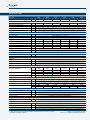
Multi-MPPT - 406V
RPS TL-UL
0450
0675
0900
1125
1350
1575
-
2
3
4
5
6
7
Maximum input current
A
700
1050
1400
1750
2100
2450
Maximum DC input voltage
V
MPPT range
V
Number of MPPT trackers
-
2
3
4
5
6
7
Number of DC inputs
-
4
6
8
10
12
14
Number of inverter modules / cabinets
Input ratings
1000
610 ... 850
Output ratings
AC voltage
V
406 (IT mains, floating neutral or ungrounded delta)
AC voltage range
V
358 - 446 (-12 % to + 10 %)
Frequency range
Hz
Rated power @ 0.9pf
kW
423
634
846
1057
1269
1480
Maximum active power
kW
450
675
900
1125
1350
1575
Maximum apparent power
kVA
478
717
956
1195
1434
1673
Rated output current
A
640
960
1280
1600
1920
2240
Maximum output current
A
680
1020
1360
1700
2040
2380
Power factor range
-
controllable 0.8i ... 0.8c (nominal > 0.99 at rated power)
%
< 3 at rated power
Current harmonic distortion
59.5 - 60.5
Auxiliary power
External power (single phase)
-
Standby power consumption
W
240 V / 10 A
40
60
80
100
120
140
Efficiency
Maximum efficiency
%
98.6 (prelim)
European weighted efficiency
%
98.4 (prelim)
CEC weighted efficiency
%
98.0 (prelim)
Mechanical details
Dimensions (WxHxD)
Weight (approx.)
Protection class
mm
1800x2100x
800
2400x2100x
800
3000x2100x
800
3800x2100x
800
4400x2100x
800
5000x2100x
800
in
71x83x31.5
95x83x31.5
118x83x31.5
150x83x31.5
173x83x31.5
197x83x31.5
kg
1300
1850
2450
3000
3550
4100
Ibs
2860
4070
5390
6600
7810
9020
-
Nema1 / IP20 (Indoor only)
-
-4°F … 131°F ('-20°C ... +55°C)*
Temperature
Ambient operating temperature range
Rel. humidity
%
up to 95 (not condensing)
Max. altitude
m
13123 ft / (derating above 3280 ft) / 4000 m (derating above 1000 m)
Req. air flow rate
m3/h
3000
4500
6000
7500
9000
10500
cfm
1766
2649
3532
4415
5298
6181
Protection and monitoring
Array grounding configuration
-
Floating
Array ground fault protection
-
Impedance Monitoring
Grid protection
-
Anti-Islanding / Adjustable voltage and frequency settings according to IEEE1547
Surge protection
-
UL1449, Class II on DC Input and AC Output
-
RS-485 (ModBus® / RTU or proprietary), Options: ModBus® / TCP over Ethernet
Interfaces
Communication interface
Standards & certifications
Standards
-
UL1741 / CSA107.1 / IEEE1547, UL1998, NEC2014
Testing
-
IEEE1547.1 / IEEE C62.41.2 / IEEE C62.45 / IEEE C37.90.1 / IEEE C37.90.2
Environmental conditions
-
EN 60721-3-3 (3K3, 3B1, 3C1, 3S2, 3M1) (unless deviating specifications provided)
Supported Power Management Functions
-
LVRT, Power Factor Control, Grid Fault Support, Power / Frequency Control and Ramp Rate
* -10°C…+45°C at rated power for Vdc < 700 V, lower minimum temperatures on request
Subject to change without notice.
Refer to user manual for detailed specification.
9
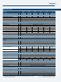
Master-Slave - 360V
RPS TL-UL
0400
0600
0800
1000
1200
1400
-
2
3
4
5
6
7
Maximum input current
A
700
1050
1400
1750
2100
2450
Maximum DC input voltage
V
1000
MPPT range
V
550 ... 850
Number of MPPT trackers
-
1
Number of DC inputs
-
variable (realized in external DC combiner)
AC voltage
V
360 (IT mains, floating neutral or ungrounded delta)
AC voltage range
V
317 - 396 (-12 % to + 10 %)
Frequency range
Hz
Rated power @ 0.9pf
kW
376
564
752
940
1128
1316
Maximum active power
kW
400
600
800
1000
1200
1400
Maximum apparent power
kVA
424
636
848
1060
1272
1484
Rated output current
A
640
960
1280
1600
1920
2240
Maximum output current
A
680
1020
1360
1700
2040
2380
Power factor range
-
controllable 0.8i ... 0.8c (nominal > 0.99 at rated power)
%
< 3 at rated power
Number of inverter modules / cabinets
Input ratings
Output ratings
Current harmonic distortion
59.5 - 60.5
Auxiliary power
External power (single phase)
-
Standby power consumption
W
240 V / 10 A
40
60
80
100
120
140
Efficiency
Maximum efficiency
%
98.6 (prelim)
European weighted efficiency
%
98.4 (prelim)
CEC weighted efficiency
%
98.0 (prelim)
Mechanical details
Dimensions (WxHxD)**
Weight (approx.)**
Protection class
mm
1800x2100x
800
2400x2100x
800
3000x2100x
800
3800x2100x
800
4400x2100x
800
5000x2100x
800
in
71x83x31.5
95x83x31.5
118x83x31.5
150x83x31.5
173x83x31.5
197x83x31.5
kg
1300
1850
2450
3000
3550
4100
Ibs
2860
4070
5390
6600
7810
9020
-
Nema1 / IP20 (Indoor only)
-
-4°F … 131°F ('-20°C ... +55°C)*
Temperature
Ambient operating temperature range
Rel. humidity
%
up to 95 (not condensing)
Max. altitude
m
13123 ft / (derating above 3280 ft) / 4000 m (derating above 1000 m)
Req. air flow rate
m3/h
3000
4500
6000
7500
9000
10500
cfm
1766
2649
3532
4415
5298
6181
Protection and monitoring
Array grounding configuration
-
Array ground fault protection
-
Negative Grounded / Positive Grounded / Floating
GFDI (inside external DC recombiner)
Grid protection
-
Anti-Islanding / Adjustable voltage and frequency settings according to IEEE1547
Surge protection
-
UL1449, Class II on DC Input and AC Output
-
RS-485 (ModBus® / RTU or proprietary), Options: ModBus® / TCP over Ethernet
Interfaces
Communication interface
Standards & certifications
Standards
-
UL1741 / CSA107.1 / IEEE1547, UL1998, NEC2014
Testing
-
IEEE1547.1 / IEEE C62.41.2 / IEEE C62.45 / IEEE C37.90.1 / IEEE C37.90.2
Environmental conditions
-
EN 60721-3-3 (3K3, 3B1, 3C1, 3S2, 3M1) (unless deviating specifications provided)
Supported Power Management Functions
-
LVRT, Power Factor Control, Grid Fault Support, Power / Frequency Control and Ramp Rate
* -10°C…+45°C at rated power for Vdc < 700 V, lower minimum temperatures on request
** excluding external dc combiner
Subject to change without notice.
Refer to user manual for detailed specification.
10
Master-Slave - 386V
RPS TL-UL
0425
0640
0855
1065
1280
1495
-
2
3
4
5
6
7
Maximum input current
A
700
1050
1400
1750
2100
2450
Maximum DC input voltage
V
1000
MPPT range
V
575 ... 850
Number of MPPT trackers
-
1
Number of DC inputs
-
variable (realized in external DC combiner)
AC voltage
V
386 (IT mains, floating neutral or ungrounded delta)
AC voltage range
V
340 - 425 (-12 % to + 10 %)
Frequency range
Hz
Rated power @ 0.9pf
kW
400
600
800
1000
1200
1400
Maximum active power
kW
427
641
855
1069
1283
1497
Maximum apparent power
kVA
454
681
909
1136
1363
1591
Rated output current
A
640
960
1280
1600
1920
2240
Maximum output current
A
680
1020
1360
1700
2040
2380
Power factor range
-
controllable 0.8i ... 0.8c (nominal > 0.99 at rated power)
%
< 3 at rated power
Number of inverter modules / cabinets
Input ratings
Output ratings
Current harmonic distortion
59.5 - 60.5
Auxiliary power
External power (single phase)
-
Standby power consumption
W
240 V / 10 A
40
60
80
100
120
140
Efficiency
Maximum efficiency
%
98.6 (prelim)
European weighted efficiency
%
98.4 (prelim)
CEC weighted efficiency
%
98.0 (prelim)
Mechanical details
Dimensions (WxHxD)**
Weight (approx.)**
Protection class
mm
1800x2100x
800
2400x2100x
800
3000x2100x
800
3800x2100x
800
4400x2100x
800
5000x2100x
800
in
71x83x31.5
95x83x31.5
118x83x31.5
150x83x31.5
173x83x31.5
197x83x31.5
kg
1300
1850
2450
3000
3550
4100
Ibs
2860
4070
5390
6600
7810
9020
-
Nema1 / IP20 (Indoor only)
-
-4°F … 131°F ('-20°C ... +55°C)*
Temperature
Ambient operating temperature range
Rel. humidity
%
up to 95 (not condensing)
Max. altitude
m
13123 ft / (derating above 3280 ft) / 4000 m (derating above 1000 m)
Req. air flow rate
m3/h
3000
4500
6000
7500
9000
10500
cfm
1766
2649
3532
4415
5298
6181
Protection and monitoring
Array grounding configuration
-
Array ground fault protection
-
Negative Grounded / Positive Grounded / Floating
GFDI (inside external DC recombiner)
Grid protection
-
Anti-Islanding / Adjustable voltage and frequency settings according to IEEE1547
Surge protection
-
UL1449, Class II on DC Input and AC Output
-
RS-485 (ModBus® / RTU or proprietary), Options: ModBus® / TCP over Ethernet
Interfaces
Communication interface
Standards & certifications
Standards
-
UL1741 / CSA107.1 / IEEE1547, UL1998, NEC2014
Testing
-
IEEE1547.1 / IEEE C62.41.2 / IEEE C62.45 / IEEE C37.90.1 / IEEE C37.90.2
Environmental conditions
-
EN 60721-3-3 (3K3, 3B1, 3C1, 3S2, 3M1) (unless deviating specifications provided)
Supported Power Management Functions
-
LVRT, Power Factor Control, Grid Fault Support, Power / Frequency Control and Ramp Rate
* -10°C…+45°C at rated power for Vdc < 700 V, lower minimum temperatures on request
** excluding external dc combiner
Subject to change without notice.
Refer to user manual for detailed specification.
11
Master-Slave - 406V
RPS TL-UL
0450
0675
0900
1125
1350
1575
-
2
3
4
5
6
7
Maximum input current
A
700
1050
1400
1750
2100
2450
Maximum DC input voltage
V
1000
MPPT range
V
610 ... 850
Number of MPPT trackers
-
1
Number of DC inputs
-
variable (realized in external DC combiner)
AC voltage
V
406 (IT mains, floating neutral or ungrounded delta)
AC voltage range
V
358 - 446 (-12 % to + 10 %)
Frequency range
Hz
Rated power @ 0.9pf
kW
423
634
846
1057
1269
1480
Maximum active power
kW
450
675
900
1125
1350
1575
Maximum apparent power
kVA
478
717
956
1195
1434
1673
Rated output current
A
640
960
1280
1600
1920
2240
Maximum output current
A
680
1020
1360
1700
2040
2380
Power factor range
-
controllable 0.8i ... 0.8c (nominal > 0.99 at rated power)
%
< 3 at rated power
Number of inverter modules / cabinets
Input ratings
Output ratings
Current harmonic distortion
59.5 - 60.5
Auxiliary power
External power (single phase)
-
Standby power consumption
W
240 V / 10 A
40
60
80
100
120
140
Efficiency
Maximum efficiency
%
98.6 (prelim)
European weighted efficiency
%
98.4 (prelim)
CEC weighted efficiency
%
98.0 (prelim)
Mechanical details
Dimensions (WxHxD)**
Weight (approx.)**
Protection class
mm
1800x2100x
800
2400x2100x
800
3000x2100x
800
3800x2100x
800
4400x2100x
800
5000x2100x
800
in
71x83x31.5
95x83x31.5
118x83x31.5
150x83x31.5
173x83x31.5
197x83x31.5
kg
1300
1850
2450
3000
3550
4100
Ibs
2860
4070
5390
6600
7810
9020
-
Nema1 / IP20 (Indoor only)
-
-4°F … 131°F ('-20°C ... +55°C)*
Temperature
Ambient operating temperature range
Rel. humidity
%
up to 95 (not condensing)
Max. altitude
m
13123 ft / (derating above 3280 ft) / 4000 m (derating above 1000 m)
Req. air flow rate
m3/h
3000
4500
6000
7500
9000
10500
cfm
1766
2649
3532
4415
5298
6181
Protection and monitoring
Array grounding configuration
-
Array ground fault protection
-
Negative Grounded / Positive Grounded / Floating
GFDI (inside external DC recombiner)
Grid protection
-
Anti-Islanding / Adjustable voltage and frequency settings according to IEEE1547
Surge protection
-
UL1449, Class II on DC Input and AC Output
-
RS-485 (ModBus® / RTU or proprietary), Options: ModBus® / TCP over Ethernet
Interfaces
Communication interface
Standards & certifications
Standards
-
UL1741 / CSA107.1 / IEEE1547, UL1998, NEC2014
Testing
-
IEEE1547.1 / IEEE C62.41.2 / IEEE C62.45 / IEEE C37.90.1 / IEEE C37.90.2
Environmental conditions
-
EN 60721-3-3 (3K3, 3B1, 3C1, 3S2, 3M1) (unless deviating specifications provided)
Supported Power Management Functions
-
LVRT, Power Factor Control, Grid Fault Support, Power / Frequency Control and Ramp Rate
* -10°C…+45°C at rated power for Vdc < 700 V, lower minimum temperatures on request
** excluding external dc combiner
Subject to change without notice.
Refer to user manual for detailed specification.
12
RPS TL-UL System
The modular architecture of Bonfiglioli products enables selection of the best configuration based on the
characteristics of the photovoltaic plant and the site where the inverter is located.
Master-Slave
Longer expected lifetime
Multi-MPPT
Increase energy yield
HIGH
mismatch
Losses
LOW
mismatch
Losses
Central inverter
(1 MPPT)
Benefits
• The earliest morning start
• The later evening stop
• High energy conversion efficiency
• Longer expected lifetime
• The lowest failure effect
Advantages of the modular configuration.
RPS TL
(up to 7 MPPT´s)
Benefits
• The highest energy in presence of:
- Non-homogeneous light exposure
- Different PV modules characteristics
- Other plant conditions (dirt, cable length, etc.)
• Low failure effect
13
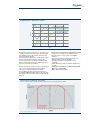
Grid Management - Other profiles possible
High Voltage Ridethrough
Voltage
Low Voltage Ridethrough
Time
The RPS TL-UL inverter includes a comprehensive set
of grid management and protection functions with
the flexibility to meet all relevant grid codes and
practices in North America.
In the standard configuration, the RPS TL-UL system
includes anti-islanding with grid voltage and
frequency protection according to UL1741 & IEEE
1547 to ensure that the inverter quickly and safely
disconnects from the local utility.
The RPS TL-UL is also designed with a comprehensive
suite of power management and grid support
functions for advanced utility power plants.
This capability was first developed in response to
the German BDEW standards and is now offered by
Bonfiglioli to meet electrical grid standards in North
America.
The functions of the advanced configuration include:
• Active power curtailment via SCADA interface.
• Reactive power control locally or via SCADA
interface.
• Fault ride-through including high voltage, low
voltage and zero voltage capability.
• Dynamic grid support and voltage control
capability.
• Controlled power ramps to minimize disturbances
on grid.
• Compatible with FERC 661A, NERC PRC 024, WECC
ONF Plan and CAISO IRRP.
• Other grid profiles possible.
Full rated power capability at .9 PF lead/lag
Active / reactive power operating range of RPS TL-UL at 112°F (45°C), Vdc < 700 V
Does not apply to variants for DC optimizers.
Branches and facilities
Our branches
Bonfiglioli
Canada
Bonfiglioli
France
Bonfiglioli
USA
Bonfiglioli
Brasil
Bonfiglioli
United Kingdom
Tecnotrans
Bonfiglioli
Bonfiglioli
Deutschland
Bonfiglioli
South Africa
Bonfiglioli
Österreich
Bonfiglioli
India
Bonfiglioli
Italia
Bonfiglioli
South East Asia
Bonfiglioli
Vietnam
Bonfiglioli
Türkiye
Bonfiglioli
Australia
Bonfiglioli
China
Bonfiglioli
New Zealand
Bonfiglioli Photovoltaic
Bonfiglioli
USA
Bonfiglioli
France
Bonfiglioli
Italy
Bonfiglioli
Vectron
Bonfiglioli
China
Headquarters
Vectron
facility
Production
facilities
Commercial
Service
Bonfiglioli
Brasil
Bonfiglioli
Spain
Bonfiglioli
South Africa
Bonfiglioli
India
Bonfiglioli Solutions
As one of the world’s leading providers of clean
energy solutions, with utility-scale PV installations
currently in place around the world, Bonfiglioli has
the innovative know-how and technical capacity to
bring commercial and utility-scale PV power plants
to life.
For the PV sector, Bonfiglioli designs and
manufactures highly efficient and innovative
electronic control systems for photovoltaic fields
and has the expertise to manage every aspect of
photovoltaic energy generation from MPPT tracking
to utility interconnection.
Bonfiglioli also designs and manufactures a complete
range of gearmotors, drive systems and planetary
gearboxes for industrial processes, automation,
mobile machinery and wind energy applications.
Over 50 years of engineering excellence makes
Bonfiglioli a preferred supplier and partner for
market leaders around the world.
For more information, visit Bonfiglioliusa.com
wind
industrial
mobile
photovoltaic
Bonfiglioli has been designing and developing innovative
and reliable power transmission and control solutions
for industrial, mobile machinery and renewable energy
applications since 1956.
Bonfiglioli USA
3541 Hargrave Drive, Hebron, Kentucky 41048
tel. (+1) 859 334 3333 - fax (+1) 859 334 8888
www.bonfiglioliusa.com
© Bonfiglioli Vectron GmbH, 2015. All rights reserved.
VE_CAT_RTLUL_USA_ENG_R02_0