1
User’s manual
Developped by 77 Elektronika KFT for UNISENSOR SA.
READSENSOR INSTRUCTIONS
-
Version 1.3
December 2007
CHAPTER I.: SHORT NOTE
Rapid Designer - How to use - Short note
PRINTING MODE & PC MODE
2 - 38
READSENSOR INSTRUCTIONS
-
Version 1.3
December 2007
3 - 38
The Readsensor can by used without PC and with PC.
To move from the use with or without PC you have to change the electronic key
(photo nb 1) that is located just close to the printer paper under the bleu cap (photo
nb 2). WHEN YOU CHANGE THE KEY PLEASE SWITCH-OFF THE READER.
There are 2 keys provided with the Readsensor: The first named “anyCheckValues”
is for the use of the paper printer and the other key “camera” allows connexion of the
readsensor to your PC. Both keys are placed into the small plastic pouch.
For using the paper printer, proceed as follow:
1. connect the small keyboard (photo nb 3).
2. connect to power supply (photo nb 3).
3. Switch-on (rear panel, photo 3) and after 2 sec the system ask for the name of
operator. Introduce the name with the keyboard and press ENTER with the
keyboard.
4. The system request to have a BLANK dipstick. Take the tray and deposit a
blank dipstick into the furrow of the tray. The dipstick must facing out of the
reader. The sample pad of the dipstick must be visible outside the reader
when the dipstick is introduced. If the dipstick is in the wrong position, turn it
for 180° like in the photo nb 4. IT IS VERY IMPORTANT TO INTRODUCE
THE DIPSTICK IN THE RIGHT WAY THAT IS THE SAMPLE PAD ALWAYS
OUTSIDE (facing out).
5. The system make the blank calibration automatically and than ask for the type
of test you want to run. Switch on the black button from the reader to indicate
the type of test and for running a Twinsensor, switch on the first black button
just under TWIN.
6. The reader request to have a CHECK dipstick and you have to introduce the
check lot number with the keyboard, so please type 051612 and ENTER.
7. Enter the EXP date that is 16/12/2006 and ENTER, note that the year should
be in 4 numbers.
8. The reader ask you to pull the BLANK dipstick out and to insert a TWIN
CHECK dipstick in. Remember the way to insert always the sample pad
outside the reader (photo nb 4).
9. Now the system print a small ticket indicating that the blank and check have
been done correctly. The reader is now free for any additional measurements.
To continue please switch on “Measure” the first black button again.
10. Tell what you want to do for instance switch on START, again the first button.
11. Tell the type of test: again the first black for Twinsensor reading.
12. Inter the test code that is BT00640 ENTER with the keyboard.
13. Enter the LOT number in 6 numbers like 061303 ENTER.
14. Enter the EXP date like for the check EXP date : 13/03/2007 ENTER
15. Enter the SAMPLE ID: like MILK Nb1 ENTER
16. The reader ask you to pull the dipstick out, until you see the indication “Insert
a dipstick” and than introduce it in the right position like on the photo nb 4.
Than the system display and print the paper.
READSENSOR INSTRUCTIONS
-
Version 1.3
4 - 38
December 2007
17. There is the result on the reader screen and if you want to screen all
information print on “print-out” (second black button) again and again to see
the list of information that were printed.
If you wish to continue the reader will keep in memory all information but you are
always obliged to type the sample name or to leave it blank.
To do so, switch on START (first black button) and than on ENTER with the
keyboard to accept what is on the screen, if you want to change you can change
using the keyboard.
PHOT 1: Electronic key:
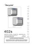
PHOTO 2 : Location of Electronic key:
Electronic Key location
READSENSOR INSTRUCTIONS
-
Version 1.3
5 - 38
December 2007
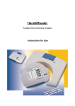
PHOTO 3: Rear panel of the Readsensor:
Switch-on/off button
Serial port to computer serial port
Power supply
Keyboard
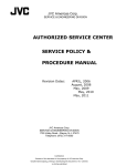
PHOTO 4: Position of dipstick into the tray holder for the Readsensor.
Sample pad of dipstick always
outside facing the operator.
The arrow indicates the direction to
introduce the tray into the reader.
The arrow indicates also the
direction of the milk liquid running
onto the dipstick.
TAKE CARE ON DIPSTICK POSITION IN THE TRAY HOLDER.
Dipstick must be “PLANNAR” and placed suitably in the groove of the black dipstick
tray. Ensure that the lower edge of the dipstick (the edge which was in milk), is
against the lower edge of the groove (the edge close to the part for holding the black
tray).. If dipstick is badly positioned the reading can be disturbed.
For using with the computer, proceed as follow.
1. Switch-off the reader.
2. Open the blew cover and replace the electronic key by the “camera” electronic
key.
3. Connect to computer with the serial cable.
4. Switch-on the reader.
READSENSOR INSTRUCTIONS
-
Version 1.3
December 2007
6 - 38
Installation
Insert the CD and go to READSENSOR SOFTWARE 702, and start SETUP and
follow the instructions to install the Rapid Designer program to your computer.
Connect the reader through its serial line to the serial port of your computer.
Start the Rapid Designer program and choose the proper serial port using the Ports
section of the window.
Switch the reader on.
The Rapid Designer program
The program displays the image of the reader, together with the curve(s) which is
(are) calculated based on it.
The curves are the integration of the pixel values in vertical direction. Only those
pixels are used (and integrated) which are between the two horizontal red lines. So
only that part of the image is used for any further processing (curve calculation, data
saving) which are between the lines. The test and control line related data are
displayed on the bottom side of the window. (position, tolerance, area, amplitude)
1. Change the test type
The radio buttons at the right bottom side of the Rapid Designer window could be
used to choose the required type of test. When one of these buttons is clicked the
reading will restart.
2. Taking white image (blank calibration)
Take a ”blank” image of the unused dipstick first. The Normalized values are
calculated based on it.
Insert the unused dipstick into the reader. Wait while the full image is displayed and
set the proper lighting. It can be done by clicking to the Increase light or Decrease
light and displaying the white, blank curve (can be viewed by choosing white in the
View section). The current light setting is displayed in the status row of the window
(bottom). (e.g.: Lighting: 5)
The white curve should not reach the top of the diagram (because it means that
saturation). Store the white curve by clicking the Blank calibration button on the
bottom of the window. The white image can be displayed any time by choosing
White in the Picture section.
Set also the start line, where the picture will start. It can be done by clicking the
Increase start ccd line and Decrease start ccd line, next to the display field.
Store the lighting and start line by clicking the Save lighting and lines button.
3. Taking and analyzing images
The program refreshes the display and displays the actual image of the reader
automatically if the Actual is set in the Picture section. It can be stopped and
restarted by clicking on the Stop and Start buttons upper side of the window.
READSENSOR INSTRUCTIONS
-
Version 1.3
December 2007
7 - 38
Teach the line position to the Reader:
Before doing any changes, please note the setting value of “position” and “tolerance”
in order ot re-set whenever you want.
Line Position and Tolerance are set into the system but you can teach the line
position at any time as follow:
Insert a used strip to the reader, and wait while the full image is displayed.
1. Select that line which would be set. It could be done by click on the little circle
button in the proper line section on the bottom of the window. (Test line 2,
Control line, Test line 1)
2. Clicking the left mouse button at the desired line position on the image of the
strip (upper picture)
3. The line positions could be set in the other way. Write the desired line position
in the desired line section (Test line 2, Control line, Test line 1) and press
Enter.
Set the line tolerances:
Write the desired line tolerance in the desired line section (Test line 2, Control line,
Test line 1) and press Enter.
When the position and the tolerance of the lines is set they could be saved by
clicking the Save lighting and lines button.
The curves are displayed on the diagram section of the window. The following
curves can be calculated and displayed:
White: the stored white/blank curve is displayed
Actual: the curve of the actual image
Normalized = (Actual/White)*100
If the Clear (in the bottom left corner) function is set, only the last selected curve is
displayed. If it is not set, all the curves are displayed.
4. Save/Load data
Use the Load and Save data buttons on the upper left corner of the window. Save
data button will store the picture of the cassette and the actual light and line settings.
The Load button will display these data (picture, light and line settings).
It is practical if you use the Continuous saving button (this button is also in the upper
left corner) in the Rapid Designer program to save the pictures and data.
1. Firstly write the number that how many measurement you would like to save
to the little window at the right side of Continuous saving button.
2. Then click the Continuous saving button which will stay pressed state.
3. The program will only ask for the file name once, and then save the
measurement serially while the set number become zero. So the program will
take as many series measurement as you set in the little window on right of
the Continuous saving button.
4. The program will save your data with the previous name but an increasing
number will be added to the file name. (i.e.: sample_006.rap)
5. When this number becomes zero the continuous saving button will be
unpressed state automatically but the series measurement could be stopped
by click the Continuous saving button.
READSENSOR INSTRUCTIONS
-
Version 1.3
8 - 38
December 2007
IMPORTANT! : When the moving line in the picture is not visible do not use the
saving function!
Database function:
If you click the Datatable button on the upper side of the Rapid Designer program an
other window will appear. This is the data collector window which can open and save
.dbf files.
1. Firstly a .dbf file need to be created or opened to start collect the data.
2. Click on the Open or create a table button then choose an exist .dbf file or
write in a new name.
3. Now the program ready to collect data. (the 3 area and amplitude values)
4. The data line number which you want to collect could be set on the bottom
side of the data table window. (The default values is 10) This little window
works like at the Continuous saving function.
5. A new data line will be added to the data table when the picture comes up
fully.
6. If the all data line which you set is collected the data table could be saved by
click on Save and close table button.
The saved .dbf extension file could be opened in MS Excel for the further evaluating.
Creat data table
Save table
1 data line
The „little” window for set the
number of series data line
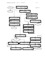
READSENSOR INSTRUCTIONS
Moving line
Test line 2
-
Version 1.3
Control line
9 - 38
December 2007
Lighting set buttons
Test line 1
Start ccd line
Averages
Seeking limits (red lines)
Ratios of the lines
„Little” circle buttons
Test type
Integration limits (light
blue lines)
Line related data
Change style of the diagram
READSENSOR INSTRUCTIONS
-
Version 1.3
December 2007
CHAPTER II.: General User’s manual
Version 1.2 - Pending the upgraded version.
10 - 38
READSENSOR INSTRUCTIONS
-
Version 1.3
December 2007
11 - 38
1
INTRODUCTION................................................................................................ 12
2
SYSTEM DESCRIPTION ................................................................................... 12
2.1
2.2
2.3
3
Twinsensor or Tetrasensor dipsticks......................................................................................................... 12
Measuring principles ................................................................................................................................ 13
Components and Functions....................................................................................................................... 16
SOFTWARE....................................................................................................... 16
3.1
Overview .................................................................................................................................................. 16
3.2
Menu Structure (Flowchart)...................................................................................................................... 16
3.3
Readsensor Menu detailed description ..................................................................................................... 20
3.3.1
The MEAS. menu ............................................................................................................................. 20
3.3.2
The SETTINGS menu ...................................................................................................................... 22
3.3.3
CHECK menu................................................................................................................................... 25
4
4.1
4.2
READSENSOR INSTALLATION AND QUICK START..................................... 26
Hardware checklist ................................................................................................................................... 26
Instrument connection .............................................................................................................................. 26
5
CHECK MEASURE............................................................................................ 29
6
NORMAL MEASURE......................................................................................... 30
6.1
6.2
6.3
6.4
Blank calibration....................................................................................................................................... 30
Sample preparation and application.......................................................................................................... 31
Result Report ............................................................................................................................................ 32
Strip Measurement Error .......................................................................................................................... 32
7
INTERPRETATION OF RESULTS .................................................................... 32
8
CLEANING AND MAINTENANCE .................................................................... 33
9
ERROR AND WARNING MESSAGES.............................................................. 33
10
CONNECTING TO OTHER DEVICES ............................................................ 35
10.1
10.2
RS 232 Serial Interface ............................................................................................................................. 35
AT/PC Keyboard ...................................................................................................................................... 35
11
TECHNICAL INFORMATION AND NOTICES................................................ 36
11.1
11.2
11.3
Technical Data .......................................................................................................................................... 36
Safety Notices........................................................................................................................................... 37
Manufacturer's Warranty .......................................................................................................................... 37
READSENSOR INSTRUCTIONS
-
Version 1.3
December 2007
12 - 38
1 Introduction
Readsensor is a reflectance photometer designed to read and evaluate the
appropriate Twinsensor (or Tetrasensor) dipsticks. The Twinsensor was designed for
the safe and reliable detection of ß-lactams and tetracyclines compounds in milk with
high sensitivity, (only tetracycline for the Tetrasensor), which is a key feature under
the requirements of today’s high standards in quality control systems. The
Readsensor reads the dipsticks under standardized conditions, saves the results to
memory and outputs them via its own inbuilt printer and/or serial (RS 232) interface.
This instrument is designed for In Vitro Diagnostic (IVD) use for professional use
only.
BIOHAZARD: Treat all samples of animal origin as being potentially infectious.
Always observe good laboratory practice.
Using Readsensor eliminates factors known to affect visual evaluation of test
Dipsticks, such as:
• Objective readings especially in visually doubtful cases
• Different reaction time for the Dipsticks
• Automatic documentation for quality assurance purposes
• Clerical errors
2 System description
2.1 Twinsensor or Tetrasensor dipsticks.
Twinsensor (or Tetrasensor) dipsticks for the qualitative detection of total ß-lactams
and tetracycline (or tetracycline) in food products. The Readsensor works only with
these kind of dipsticks.
For professional use only.
INTENDED USE
The Twinsensor dipsticks are rapid chromatographic immunoassay for qualitative
detection of Total ß-lactams and tetracycline in food products.
The Readsensor system will only indicates qualitative level of ß-lactams and
tetracycline and should not be used as the sole criteria for concentration evaluation.
PRINCIPLE
The Twinsensor (or ,Tetrasensor) dipsticks are qualitative, nitrocellulose membrane
based immunoassay for the detection of antibiotics in food products. The principle is
described in each kit insert and can be obtained from the web site
www.twinsensor.com and www.tetrasensor.com.
PRECAUTIONS:
• Read the kit insert Manual carefully before installation so as to ensure
proper operation of the analyzer from the outset.
• Do not use any components of the kits after expiration date.
• Do not eat, drink or smoke in the area where the specimens or kits are
handled.
• Handle all specimens as if they contain infectious agents. Observe
established precautions against microbiological hazards throughout the
procedure and follow the standard procedures for proper disposal of
specimens.
READSENSOR INSTRUCTIONS
-
Version 1.3
December 2007
13 - 38
STORAGE AND STABILITY
The kit can be stored refrigerated (2-8°C). The test device is stable through the
expiration date printed on the label. The microwells and dipsticks must remain in
their original sealed pouch or bottle until use.
WARNING: Do not freeze. Do not use beyond the expiration date.
2.2 Measuring principles
The Readsensor uses the incident light emitted by an internal light source reflected
by the test strip surface as primary information. In other words the reader sees
exactly the same thing as the human eye does, except the fact that the colour of the
light source is adjusted to the spectral properties of the test strip in order to improve
contrast and sensitivity. That is why green light is radiating from the insertion window
during the measurement.
CAUTION: As the reader sees the same way as the human eye does, it is
subject to the same interfering effects. No other object should be placed over
the test strip before insertion. The surface of the strip should be plain, no
bending of the strip is allowed. The surface must be free of scratches and
other disturbing objects (drawing, writing, dust etc.). It is recommended to
take care of the correct positioning of the strip, otherwise it going to give
incorrect results.
READSENSOR INSTRUCTIONS
-
Version 1.3
14 - 38
December 2007
Reflectance to
detector
1
Light source (green LEDs)
2
Test dipstick
Reagent strip in dipstick format
Lens
4
S
e
n
s
o
r
Mirror
Microprocessor
3
2
Result
Test strip on holder
The reflectance image is projected with an optic onto a CCD sensor, which resolves
the picture into 320x90 pixels along the test strip. The optical density curve has a
lower value in positions where the strip is dark and it has a higher value where the
strip is close to white. The reader does all further processing on the resulting optical
density curves.
The user moves the dipstick under the LED reading head and the mirror. The
analyzer reads the control, and the test lines on the dipstick. Reading is done
electro-optically, as follows:
The LED (1) emits light of a defined wavelength on to the surface of the test pad (2)
at an optimum angle. The light hitting the test zone is reflected more or less intensely
depending on the darkness of the lines on dipstick, and is picked up by the detector
through a mirror and a lens. The lens produces an upside-down image on surface of
the CCD (3). The CCD consists of an A/D converter, and sends a digital electrical
signal to CPU. Then the microprocessor (4) converts this digital reading to a relative
reflectance lighting curve by referring it to a calibration standard (blank) lighting
curve.
The reader calculates a ratio number from the integration area of the coloured lines
on the test Dipstick surface.
Test dipstick is read photometrically after a lead (incubation) time. The CCD can see
the entire surface of the test strip, but it is directed onto a 32 pixel wide zone of the
relevant reaction area. The „footprint” of the optics – the area, which is projected
onto the sensor array - is called the field of view (FOV).
READSENSOR INSTRUCTIONS
-
Version 1.3
15 - 38
December 2007
The width of the dipstick is about 5mm and it is measured in the cross direction of
the strip. The limits of the FOV are measured along the strip and are fixed for all
Readers. The reader recognises the darkness and colour change only within the
FOV.
The illumination of the test strip and the sensitivity of the CCD element are not
uniform along the FOV and not constant in long term. Due to these facts the reader
has to make a white calibration or blanking on a regular base. With the blanking
procedure it is possible to equalize the non-uniformity of the optics as it is shown
above. After a blank calibration a blank Dipstick is measured to have the same
colour at each position.
WARNING: The blank calibration procedure is essential for the proper
operation of the ReadSensor that is why the operator is forced to repeat it
regularly.
During real measurements, which may only happen after a blank calibration, the
equalized optical density curve (relative reflectance curve) will look like shown below.
ρ(x)
Test line:
TETRA
Control line
Test line
x
The evaluation of the Twinsensor or Tetrasensor dipstick is the following: There is a
control line and two test lines on the dipstick of the Twinsensor and only one test line
on the dipstick of the Tetrasensor. The reader calculates a ratio number from the
integration area of these coloured lines on the reagent surface then compares this
ratio with defined calibration curve range limits and outputs a qualitative result.
*The photometrical precision of the device remains below the precision of
immunological measurements. The accuracy of the system derives from the dipstick.
Please, refer to the User's Manual of the kit product for further information.
READSENSOR INSTRUCTIONS
2.3
-
Version 1.3
16 - 38
December 2007
Components and Functions
9
9
1
2
4
7
5
6
8
3
Component
1. Printer cover
2. Display/keypad
3.
4.
5.
6.
7.
8.
9.
Test dipstick slot
On/Off switch
Power socket
PS 2 socket
RS 232 interface
RJ 11/6 connector
Program chip (key)
Function
Flips up for insertion of printer paper
LCD display and three function keys for menu-driven
operation and interfacing with the user
Receives the dipstick tray
Powers the unit on and off
Socket used to connect the analyzer to the mains adapter
For connecting a PC keyboard
For connection to a personal or host computer
Connector is used only in manufacturing or servicing
(under the printer cover) Contains the software needed to
drive the analyzer, as well as the standard range limits
3 Software
3.1 Overview
The Readsensor software provides a user interface that enables all laboratory
specific settings and recurrent functions to be selected via the liquid crystal display
and function keys (see Sections 3.2 and 3.3).
The three function keys assume the particular function displayed on the second line
of the liquid crystal display. The first line of the display is used for system status and
user information.
The user interface is self-explanatory, so that only details of the major functions are
presented here.
Pressing the BACK button within any submenu to return to previous menu
screen.
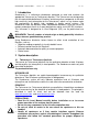
3.2 Menu Structure (Flowchart)
Have a look to the Readsensor screen menu
READSENSOR INSTRUCTIONS
-
Version 1.3
START
Op name?:
Check menu
BLANK
Back
PLEASE WAIT…
Back
17 - 38
December 2007
PrON/FF
Back
Ok
Waiting a
new blank
test.
CHECK
Back
PLEASE WAIT…
Stabilization
and checking
the position
Back
BLANK IN PROGRESS
Back
Calibration
Measure
TYPE OF TEST
Twin/Tetra
Twin ----------- Tetra ---------- Back
Twin/TetraSensor
EXP date:
Ok
Stabilization
and checking
the position
READING IN PROGRESS…
Back
Twin/TetraSensor
CHECK LOT nb: Ok
Waiting
a new
check.
Back
No
Yes
Is the check
meas. Valid?
CHECK NOT ACCEPTED
Restart
Printout
Quit
Print
Back
Restart
<< Printout lines >>
Next Line
Quit
CHECK CCEPTED
Measure
Printout
Esci
Measure
Quit
Print
<< Printout lines >>
Next Line
Quit
Start menu
Error messages:
E20: WRONG DATE
E25: EXTERNAL LIGHT
Next
Quit
E04: WRONG CODEKEY
E21: WRONG TEST CODE
E28: BLANK / OPTIC FAULT
OK
New Cal.
Quit
E05: NO CODEKEY
E22: CALIBRATION ERROR
E30: WRONG FORMAT
E06: SAMPLE INVALID
Next
E23: PRINTER ERROR
Quit
Quit
READSENSOR INSTRUCTIONS
-
Version 1.3
18 - 38
December 2007
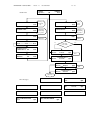
ReadSensor
PrON/FF
Start
-Check -- Settings
Start menu
Check
menu
No
Is the blank
calibration valid?
(<24h)
Settings
menu
Yes
TYPE OF TEST
Twin/Tetra
Twin ----------- Tetra ---------- Back
BLANK
Back
PLEASE WAIT…
Back
Waiting a
new blank
test.
Stabilization
and checking
the position
BLANK IN PROGRESS
Twin/TetraSensor
Test code:
Ok
Back
Twin/TetraSensor
KIT LOT:
Ok
Back
Twin/TetraSensor
EXP date:
Ok
Back
Twin/TetraSensor
SAMPLE ID:
Ok
Back
Go to the check
menu in case of
choose a non
checked test.
Back
Calibration
NEW TEST
Back
PLEASE WAIT…
Back
Waiting
a new
test.
Stabilization
and checking
the position
READING IN PROGRESS…
Back
Measure
Restart
<<RESULTS>>
Printout
Quit
Print
Restart
Misura
<< Printout lines >>
Next Line
Quit
Riga succ.
READSENSOR INSTRUCTIONS
-
Version 1.3
19 - 38
December 2007
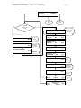
ReadSensor
PrON/FF
Start
-Check -- Settings
Start menu
Settings menu
SETTINGS
Organisation
Check menu
Output
Back
Impostaz.
OUTPUT
Print/Send
DISPLAY
Language
ORGANISATION
Name: _____________________ Back
PrON/FF
Display
Date/Time
Back
DD/MM/YYYY
-
ADDRESS
Address: ___________________ Back
ADMINISTRATOR
Name: _____________________ Back
Back
+
HH:MM:SS
Next
Main menu
Main menu
PRINT/SEND
Printer
Memory
LANGUAGE:
OK
ENGLISH
Next
LANGUAGE:
OK
1.1.1.1
XXXXXXX
Next
Quit
LANGUAGE:
OK
1.1.1.2
XXXXXXX
Next
Quit
Quit
PrON/FF
Back
Select
report.
SELECTED LAST = ____
Change
OK
Yes
Printer
On?
Back
No
TRANSMISSION IN PROGRESS
PRINTER
OFF
Linefeed
PrON/FF
Back
PRINTER
ON
Linefeed
PrON/FF
Back
Sending
data.
PRINT
Yes
Main menu
LINEFEED
Start
No
PRINTING…
Stop
Back
Quit
Quit
Main menu
Printing.
READSENSOR INSTRUCTIONS
3.3
-
Version 1.3
December 2007
20 - 38
Readsensor Menu detailed description
The user can choose from the sub-menus by pressing buttons under the display.
The current function of the pushbuttons is indicated right above on the display. To
leave the current sub-menu and return to the Main Menu, press the Quit button. To
return to the previous screen/menu press Back button.
Meas.
Starts the measurement.
Check
Run a check measurement.
Settings
The setting of the instrument.
3.3.1 The MEAS. menu
A routine measurement can be carried out under this menu.
Type of TEST
Select the type of test among Twinsensor TWIN or Tetrasensor TETRA.
Start
Measure with the actual Type of Test.
Back
Back to the main menu
Test code
Introduce the code of the kit in use that should looks like “AB12345”
Kit lot number
Introduce the kit lot number that is indicated on any kit labels and press ENTER with
the keyboard. The number can be found in the packaging of the Dipstick. The
number storages in the device after the first typing. If the number is invalid an error
message will appear. If no keyboard is attached, the number can be given by the
buttons of the devices.
Expiry date
Introduce the expiry date that is written on any kit labels. It must be in the following
format DD/MM/YYYY .
OK
Accept the actually selected items.
BLANK STRIP
A non-used white strip is needed for blank calibration.
Insert a non-used Dipstick into the reader in order to carry out a blank calibration.
Ensure the proper positioning of the strip. After insertion, the reader automatically
recognises the strip and switches to a new screen.
READSENSOR INSTRUCTIONS
-
Version 1.3
December 2007
21 - 38
Back
Stops the waiting for the non-used strip and return to the Meas. menubox.
PLEASE WAIT…
Check the fixed position of the blank Dipstick. That is important for the proper blank
calibration. If it passed automatically switches to a new screen.
Back
Cancel the calibration and return to the Meas. menubox.
BLANK IN PROGRESS
The blank calibration.
As the reader recognised the non-used strip, it starts to carry out a calibration
automatically. Wait until the next screen appears.
Back
Cancel the calibration and return to the previous screen.
BLANK TIME
The blank calibration is valid for twenty-four hours. Within this period, there is no
need to carry out blank calibration again (except the Reader switch off or carry out a
check measure).
SAMPLE ID:
Enter the sample ID to be tested.
Type the sample by using the keyboard. It can be 15 characters long (depending on
the language setting). User can use alphanumerical characters Press <ENTER> on
the keyboard to enter the name. The typed code/name/number will not remain to the
next measuring cycle. The user has to type it in for every measurement. The reader
accepts empty identifier field too.
OK
Accepts without any identifier. (OK will disappear if any key pressed on the
keyboard)
Back
Cancel the modification of patient name and return to the Meas. menubox.
OK
Accepts without any identifier. (OK will disappear if any key pressed on the
keyboard)
Back
Cancel the modification of birthday and return to the Meas. menubox.
NEW TEST!
Insert the strip to test into the reader. Ensure the proper positioning of the strip. After
insertion, the reader automatically recognizes the strip and switches to a new
screen.
Back
Stops the waiting for the test strip and return to the Meas. menubox.
READSENSOR INSTRUCTIONS
-
Version 1.3
December 2007
22 - 38
PLEASE WAIT…
Check the fixed position of the test Dipstick. That is need for the proper reading of
test. If it passed automatically switches to a new screen.
Back
Cancel the reading and return to the Meas. menubox.
READING IN PROGRESS
The reading and the evaluation of the test strip.
As the reader recognized the test strip, it starts to carry out the reading and the
evaluation automatically. The evaluation is done based on the pre-defined test strip
features.
It takes about 10 seconds after complete insertion.
Wait while the next screen appears.
Back
Cancel the reading and return to the previous screen.
RESULT:
The qualityative result is displayed.
Measure
Carry out a new measurement again.
Readout
The report printout can be displayed line by line. The first line is displayed and then
the next display will appear.
Quit
Return to Main Menu
[printout line]
Displaying the lines of the report printout in the upper row of the display.
Measure
Carry out a new measurement again.
Next Line
Displays the next line of the printout report. At each button press the next line is
displayed. After the last line the first one is displayed again.
Quit
Return to Main Menu
3.3.2 The SETTINGS menu
Setups and settings of the reader, reading memory recall / transfer and enter the
user address can be done under this menu.
SETTINGS
User name or Administrator
Enter the user name administrator. It can be some information about the measuring
place, person or other important things about the measure.(in five rows)
Output
Set the output features of the meter.
USER ADDRESS:
(LINE X )
Write the X line of the user address. Number of the current line displayed on right
side of the LCD’s first line. Each row can be 20 characters.
READSENSOR INSTRUCTIONS
-
Version 1.3
December 2007
23 - 38
Press <ENTER> on the keyboard to enter the current line. The equipment stores it
after the switch off too.
↑
Return to the Settings menubox.
OUTPUT
Output features of the reader can be set under this sub-menu.
Print/Send
Printer settings and memory access for printing out and sending to a host PC.
Display
Display (date/time and language) settings.
Back
Return to the previous screen.
PRINT/SEND
Printer settings and memory access to printouts and sending to a host PC.
Printer
The online printing (reports are printed out immediately after the measurement) can
be switched on or off.
Memory
Memory access for printing or sending.
Back
Return to the previous screen.
PRINTER
PrON / PrOFF
The indicator is displayed according to the current setting on the upper right corner
of the display.
OFF/ON
Alter the printer setting and return to the Main Menu.
(For switching off the printer when the printout of results is only required at the end of
a series of readings (activated by the "Print/Send" function), or when results are to
be sent via the interface to a personal computer or host only)
Linefeed
Feeds paper into the printer or causes paper to advance.
Back
Return to the previous screen.
LINEFEED
Paper forwarding control.
Start
Start the paper forwarding.
Stop
Stop the paper forwarding.
Quit
Return to Main Menu.
SELECTED LAST = XX
Select the number of reports to be printed out and sent to the PC.
Type the number in using the keyboard. The memory capacity of the reader is 26
reports, so the last 26 or less report will be printed out and sent. If the memory is full
the automatically overwrite the oldest report. The details of sending to PC can be
found in the chapter PC CONNECTION. Press <ENTER> on the keyboard or press
READSENSOR INSTRUCTIONS
-
Version 1.3
December 2007
24 - 38
OK button to enter the number. If enter a greater number than the number of data
blocks in the memory, it change to number of data blocks. The displayed number
after entering this menu can be accepted and immediately send the dates to PC by
pressing <ENTER> or OK
OK
Enter the number of the reports to be printed out and sent.
Back
Return to the previous screen.
PRINT
It can be chosen whether the reports should be printed too.
Yes
Print out the reports.
No
Do not print out the reports.
Quit
Return to Main Menu.
PRINTING
Printing is in progress.
Quit
Cancel printing and return to Main Menu.
DISPLAY
Display (date/time and language) settings.
Language
Language selection.
Date/Time
Date and time setting.
Back
Return to the previous screen.
dd/mm/yyyy
HH:MM:SS
The currently set date and time are displayed. All fields can be set, from year to
seconds.
+
Increase the current field.
Decrease the current field.
Next
Move the blinking cursor to the following field. After the last field, return to the main
menu.
LANGUAGE:
For the moment the available language of the display and the report printouts is
English.
OK
Select the currently displayed language.
Next
Skip to the next language.
Quit
Return to Main Menu without changing the current language setting.
READSENSOR INSTRUCTIONS
-
Version 1.3
December 2007
25 - 38
3.3.3 CHECK menu
A check measurement can be carried out under this menu.
BLANK STRIP
A non-used white strip is needed for blank calibration.
Insert a non-used Dipstick into the reader in order to carry out a blank calibration.
Ensure the proper positioning of the strip. After insertion, the reader automatically
recognises the strip and switches to a new screen.
Back
Stops the waiting for the non-used strip and return to the Main menu.
PLEASE WAIT…
Check the fixed position of the blank Dipstick. That is important for the proper blank
calibration. If it passed automatically switches to a new screen.
Back
Cancel the calibration and return to the Main menu.
BLANK IN PROGRESS
The blank calibration.
As the reader recognised the non-used strip, it starts to carry out a calibration
automatically. Wait until the next screen appears.
Back
Cancel the calibration and return to the previous screen.
BLANK TIME
The blank time is not valid in check mode. Each check measure needs a blank
calibration. But after the check measure it is not need in normal measure mode for
twenty-four hours. Within this period, there is no need to carry out blank calibration
again (except the Reader switch off/on or carry out a check measure).
PLEASE WAIT…
Check the fixed position of the check card. That is need for the proper reading of
Dipstick. If it passed automatically switches to a new screen.
Back
Cancel the reading and return to the previous screen.
CHECK LOT nb:
Introduce the lot number of the Check dipsticks that are used.
READING IN PROGRESS
The reading and the evaluation of the test strip.
As the reader recognised the check Dipstick, it starts to carry out the reading and the
evaluation automatically. The evaluation is done based on the pre-defined test
Dipstick features.
It takes about 20 seconds after complete insertion.
Wait while the next screen appears.
Back
Cancel the reading and return to the previous screen.
READSENSOR INSTRUCTIONS
-
Version 1.3
December 2007
26 - 38
4 Readsensor installation and quick start
WARNING: Read the Readsensor User's Manual carefully before installation so
as to ensure proper operation of the analyser from the outset.
For a quick installation the following simple steps should be done:
• Refer to Short Note section: Installation on page 6.
• verify the hardware checklist
• checking for damage during transport
• connect the accessories and your PC to the reader according to your need
• make the initial basic settings on the reader
4.1
Hardware checklist
Upon receipt, check that the Readsensor box contains all of the following items:
• 1 Readsensor
• 1 Dipstick tray
• 1 AC Adapter
• 1 AC connecting cable for the adapter
• 1 roll of thermo printer paper
• 1 User's Manual
CAUTION: To ensure your readings are always accurate, do not set up
Readsensor in close proximity to devices that create high-frequency fields, as
they may interfere and produce false results. Such devices include, for
instance, walkie-talkies, mobile telephones, microwave ovens and diathermic
equipment.
ATTENTION: In the event of damage to goods during transit, contact your local
representative.
ATTENTION: If your analyzer has been exposed to marked changes in
temperature and/or humidity wait for it to acclimatize sufficiently before
operating it.
4.2
Instrument connection
Power-on
(1) Unpack the Readsensor and place it on a stable, level surface. Do not expose
the analyzer to direct sunlight or other source of direct light (for example a spot
lamp).
(2) Connect the AC adapter to the power socket at the rear of the instrument and to
an AC wall socket.
(3) Switch on the Readsensor using the on/off switch at the rear of the instrument.
(4) When all the elements are properly connected and the reader is plugged into the
mains socket version information should appear first for 3 seconds followed by
the Main Menu screen on the LCD. If you get an E05: NO CODEPIN error
READSENSOR INSTRUCTIONS
-
Version 1.3
December 2007
27 - 38
message on the screen, please open the printer cover and check whether the
code pin is properly placed in the nut on the left of the printer paper roll. The code
pin should be sitting firmly in its position, if it is loose, insert it properly. This
happens whenever the instrument is switched on. If an error occurs, consult the
User’s Manual or contact your local Readsensor representative.
Basic initial settings before starting any measurement
Normally, there are three things to do before starting the first measurements.
- Insert a new paper roll if there is no paper in the printer
- Set the proper language
- Check the date and time
Paper insertion
Flip open the printer cover of the instrument (instrument must be switched on). The
paper roll is easily inserted if it is cleanly cut with a scissors. Hold the printer paper
with the thermosensitive side facing downward and insert it into the lower printer slit.
Press the linefeed function key. The paper is automatically fed in. Let the printer
proceed with the paper insertion until several centimetres are visible on the printer’s
output slit. Press the left function key "Stop", close the printer cover with one hand,
and use the other hand to feed the paper in such a way that it protrudes above the
printer cover and is not jammed. This avoids malfunctions.
ATTENTION: To remove the printed test report, tear off the paper by pulling it
in front across the edge of the printer cover. The paper must protrude above
the slit.
(5) In order to insert a new paper roll, first remove the eventual remaining piece of
the previous roll. If necessary pull the paper out from the upper paper-out slit.
Reverse movement of the paper is not possible, forcing the wrong direction
can lead to damage. Take a new paper roll, cut off the adhesive tape if
necessary and cut a clean, sharp edge for insertion. Open the printer cover and
put the paper roll into its position. Take the edge of the paper and insert it
horizontally into the paper-in slot. The smooth, shiny side (outer surface of the
roll) should be facing down otherwise there won’t be any normal printout. Using
the user menu and the pushbuttons, enter the menu Setting \ Output \ Print/Send
READSENSOR INSTRUCTIONS
-
Version 1.3
December 2007
28 - 38
\ Printer \ Linefeed \ Start. The printer should start forwarding blank lines on this
action, the paper edge should be adjusted into the paper-in slit until the paper
forwarding mechanism of the printer takes hold of it. When the paper length at
the paper-out slot has reached about 2-3 cm press the Stop button for a second
to finish the linefeed procedure. After this, close the printer cover so that the
paper juts out through the printer cover’s slit.
(6) To set the language of your choice, press the key sequence "Settings / Output /
Display / Language" (see Sections 3.2 and 3.3).
(7) Press the key sequence “Settings / Output / Display / Date/Time” to set the
proper date and time settings (see Menu Structure, Section 3.2).
(8) Readsensor leaves the factory with the default settings for Printer, Language and
Date/time (see Menu Structure, Section 3.2). If your laboratory works differently,
individual preferences can be entered via the menus.
Power-off
We recommend that the analyzer be switched off at the end of each working day and
that the mains adapter be unplugged from the AC wall socket (see Section 7,
Cleaning)
READSENSOR INSTRUCTIONS
-
Version 1.3
December 2007
29 - 38
5 Check measure
Readsensor is calibrated before leaving the factory. When installed, it must be
recalibrate with Check Dipstick before the first samples are read, and thereafter
every hundredth measure. Check Dipstick strip has three check lines on it. That is
standardized to give constant, defined reflectance readings. The purpose of the
check measure is to verify for ageing effects, failure and infection of the optical
system. Check lines on the check dipstick have exact area values, which required
during the check measure. If the measured value is not in the limits the normal tests
probably will not valid.
Procedure:
Press the middle function key ("CHECK") to carry out the Check measure.
1. Take a blank calibration(See section 6.1)
2. Remove a Check Dipstick from the Check Dipstick container. Be careful not to
touch the check line surface and do not allow that those to come into infect with
anything.
3. Insert the Check Dipstick, with the check lines facing upwards, to the Reader
leading. Before calibrating, ensure that the Dipstick is clean and the strip is not
scratched.
ATTENTION: It is very important that the Check Dipstick locks into the
instrument correctly in order to ensure the quality of the calibration
4. As the reader recognised the Check Dipstick, it starts to carry out the reading and
the evaluation automatically. Check line 1, 2 and check line 3 on the strip are
read.
5. Check line areas are printed and displayed on LCD but is not stored in memory.
Remove the Check Dipstick.
CAUTION: Regular Check measurement is necessary to ensure the quality of
the results obtained. Unisensor SA. cannot warrant the correctness of results
if the system is not checked regularly.
ATTENTION: You can make a Check measurement at any time, even if the one
hundred measures have not elapsed since the last calibration, for example if a
Readsensor Test Dipstick has returned an implausible result. Start the Check
procedure by pressing the middle function key (“Check”) with the analyzer in
main menu. Follow the calibration procedure described section “Check
measure”.
Calibration errors
In case of an invalid check measure the equipment does not give any error
messages.
READSENSOR INSTRUCTIONS
-
Version 1.3
December 2007
30 - 38
6 Normal measure
6.1
Blank calibration
Readsensor is very easy to use. The first step of a measurement series is the blank
calibration. This blank calibration is necessary for the equalization of the optics, for
more details refer to the section “2.2 Measuring principles”. The blank calibration
is valid for twenty-four hours. The blank calibration should be performed with an
unused, white and clean test. The reader checks the correct positioning of the strip
and the calibration will not be carried out with a not properly placed strip. It is
important to perform the calibration carefully because a wrong calibration
might spoil all following measurements.
If there is no valid calibration, the first time must carry out one. The reader will
display BLANK STRIP and asks for a blank Dipstick for blank calibration. Insert a
blank Dipstick into equipment. If the white test was already inserted, “<<PULL
DIPSTICK OUT<<” message appear on LCD. The Dipstick has to be removed and
reinserted, the reader does not accept any strip already residing in the optics at the
start of any measurement. In the other case “>>PUSH DIPSTICK IN >>” message
displayed on LCD. When the strip is accepted the reader will display BLANK IN
PROGRESS in the first line. After it automatically set the lighting for the correct
reading (it is the countdown on the LCD).
The purpose of calibrating the analyzer is to compensate for ageing effects that
influence the optical system. If the compensation needed is excessive, for example
because the test strip is badly soiled, or an LED is defective and cannot emit the
required amount of light, an error message is displayed (see below).
Procedure
1. Tear off a normal Dipstick (The Dipstick must be totally blank and clear). Remove
the Dipstick from the bottle. Be careful not to touch the surface of strip in the
Dipstick and do not allow them to come into contact with anything.
2. Press the left side button (“Start”). “BLANK STRIP” appears.
3. When “>>PUSH DIPSTICK OUT>>” appears, place the calibration strip, with the
test window facing upwards and out with the sample-tearing window.
ATTENTION: It is very important that the blank Dipstick locks into the
instrument correctly in order to ensure the quality of the calibration
4. Equipment set the correct lighting. An acknowledging beep sounds. Remove the
blank Dipstick. It may use for an hour yet to normal measure.
READSENSOR INSTRUCTIONS
6.2
-
Version 1.3
December 2007
31 - 38
Sample preparation and application
Follow instruction in:
KIT INSTRUCTIONS
Doc: TWINSENSOR / V1.6 (or upgraded).
This document is provided with each kit.
CAUTION: There are a few aspects that should be kept in mind during
measurements:
• The reaction time has to be kept accurately.
• The correct test dipstick positioning is essential, the dipstick must be
planar with both top and bottom part included in the furrow of the rapid
designer. Some dipstick might be a bit large or small and you should
regard this as a major when loading the dipstick on the furrow.
• There are some disturbing effects that the reader itself cannot detect. The
reader can not distinguish big scratches from coloration, thus strips with
such defects should not be measured or the measurement result has to be
used cautiously.
ATTENTION: To ensure that Readsensor is carried out correctly, read the
package insert included with the test strip.
If the Dipstick was already inserted, “<<PULL DIPSTICK OUT<<” message appear
on LCD. The Dipstick has to be removed and reinserted, the reader does not accept
any strip already residing in the optics at the start of any measurement. In the other
case “>>PUSH DIPSTICK IN>>” message displayed on LCD. Insert the Dipstick into
the slot of the optics with a single continuous movement. If the strip is stopped
during its course for a longer period of time (1-2 seconds) the reader might
start the measurement. Such operation could lead to false readings despite of the
thorough measurement validity checks that the reader performs during result
evaluation. When the reader accepts the strip as stabilized it starts the measurement
procedure indicated by READING IN PROGRESS in the first line of the display. After
a few seconds the result is evaluated and is printed on paper and on demand lineby-line on the LCD screen. If the reader does not accept the strip as a valid test strip
(e.g.: missing control, reference line, or test redrawn during measurement) E06:
STRIP INVALID error message will be displayed.
5. When “>>PUSH DIPSTICK IN >>” appears, place the Dipstick, with the test
window facing upwards and out with the specimen-tearing window.
6. When Dipstick is measured, calculating the result and print and/or send it.
7. Selecting the “Measure” menu point to take another measure.
After the completion of a measurement a new one can be initiated by selecting the
“Measure” menu. This will restart the measurement procedure.
READSENSOR INSTRUCTIONS
-
Version 1.3
December 2007
32 - 38
6.3 Result Report
The result report is printed out together with the sequence number, date and time.
The sample's name may be entered manually on the printout. If a sample’s ID was
entered in advance of the reading (see Section 6.2), it will be printed out together
with the sequence number.
The reports are printed out in the following form.
6.4 Strip Measurement Error
If any error message appears during the measure, the test strip and/or analyzer have
probably been incorrectly used. Refer to Section 8 for details.
READSENSOR INSTRUCTIONS
-
Version 1.3
33 - 38
December 2007
7 Interpretation of Results
The Readsensor gives results in a qualitative form, which means in 3 ranges. One
NEGATIVE, one LOW POSITIVE and one POSITIVE.
These are the following:
For Twinsensor:
POS
when TEST / CTRL (B/C or T/C) =< 0.9
LOW POS when 0.9 < TEST / CTRL =< 1.1
NEG
when TEST / CTRL (B/C or T/C) > 1.1
For Tetrasensor:
POS
when T/C =< 0.95
LOW POS when 0.95 < T/C =< 1.3
NEG
when T/C > 1.3
For the visual interpretation of the measurement results, please, refer to the User’s
Manual of the Test Dipstick.
8 Cleaning and Maintenance
Readsensor is designed for maintenance-free operation. Protect the instrument from
extremes of temperature and high atmospheric humidity (see Section 10), and keep
it out of bright light (direct sunlight, spot lamps, etc.).
Maintain hygiene by keeping the exterior parts and surfaces of the instrument clean.
For cleaning apply a commercial cleaning agent or disinfectant (preferably 70 %
alcohol) with a moist cloth. Take care that no liquid enters the instrument.
9 Error and warning messages
The Readsensor has an intelligent error detecting system to minimize the error of the
routine test. In case of an error, together with an audible signal and the blinking of
the LED in red, a message appears on the display. An error / warning message
consists of an error code and a short text refers to the source of the error.
In case of the error messages the reader stops its functional working, what can be
continued only after the action of the user.
In case of the warning messages the reader pauses its functional working for the
short period of the warning and steps back automatically to the previous screen.
The possible error and warning messages, the possible causes and troubleshooting
are detailed in the following:
E04: WRONG CODEKEY
The chip module on the left of the analyzer
underneath the printer cover is not valid or damaged.
Check the codepin and change to a proper one.
E05: NO CODEKEY
The electronic codepin is not correctly inserted. Insert
the codepin correctly.
If the error persists, withdraws the codepin delicately,
cleans the contactors and introduces again delicately.
Codepin
READSENSOR INSTRUCTIONS
-
Version 1.3
December 2007
34 - 38
E06: STRIP INVALID
The measured strip is not valid. No test strip is present or the Dipstick is incorrectly
positioned, control line did not develop properly or a test strip different from the set
one is used. The test strip was removed during the measurement.
Press Next button to carry out a measurement again. Change the test strip to a
proper one.
E10: WRONG POSITION
The strip is not properly placed.
Check the position of the strip.
E11: WRONG LOT NUMBER
Either the wrong LOT number was entered or the codekey was replaced while the
reader was on.
E20: WRONG DATE
An invalid date was entered.
Check the date and enter the valid one.
E22: CALIBRATION ERROR
The reader was not able to carry out the calibration.
Repeat the calibration again, taking care of all the details.
E23: PRINTER ERROR
Printing failure because of the stucked paper. Switch off and clear the stucked paper,
if there is one. Switch the analyzer on again. If the error message appears again, the
instrument is defective.
E25: EXTERNAL LIGHT
An external light is affects the measured area of the Dipstick.
Do not expose the slut of the optic system to bright and direct light.
E28: BLANK / OPTIC FAULT
During the blank calibration, the calibration strip is not smooth enough or it has some
scratches / coloration at the lines position and the optic system get soiled.
Check the blank Dipstick that there is not any coloration or soil and clean the inside
mirror.
VALUES OBTAINED ARE IMPLAUSIBLE WHEN, COMPARED WITH THOSE
FROM VISUAL EVALUATION
Test Dipstick incorrectly positioned, proper incubation intervals not kept.
Electromagnetic interference from other devices (see Section 4)
Repeat the measurement with a new Readsensor Test Dipstick. Follow the
directions carefully and ensure the test Dipstick is correctly inserted. Repeat
calibration if necessary (after switch off/on). Remove external sources of
interference, if there are any.
NO PRINTOUT
"Printer: Off has been selected, or the printer/software is defective, or the printer is
out of paper. Insert paper if needed. Choose "Printer: On" to re-activate the printer.
Request a patient report via the "Print" function. If this fails, activate the "Linefeed"
function. If there is still no response, the instrument is defective.
READSENSOR INSTRUCTIONS
-
Version 1.3
December 2007
35 - 38
10 Connecting to Other Devices
10.1 RS 232 Serial Interface
The RS 232 serial interface - through which it can be connected to PC – is located at
the rear side of the Readsensor. If requested, Unisensor SA. supplies appropriate
standard data cable for data transfer between the Readsensor and host PC.
Connected PC must satisfy the electrical safety requirements laid down in EN 60950.
The protocol is unidirectional, with the following parameters:
9600 Baud
8 databits
No parity
1 stopbit
Data cable: D-sub, 9-pin, male on instrument side, female on PC side.
Connections:
1
1
2―–– RxD –––– 2
3―–– TxD –––– 3
4―–– DTR –––– 4
5―–– GND –––– 5
6
6
7
7
8
8
9
9
Records stored in the memory can be transmitted from the Readsensor to PC. That
is how old measurements can be archived on host PC. On PC side only a serial
terminal program is needed for successful data transfer. Any kind of serial terminal
program can be used. The manufacturer recommends the use of Hyperterminal,
which is supplied with every Windows operating system.
CAUTION: Use of data cable not meeting the specification of the manufacturer
may damage the Readsensor or may result data loss.
10.2 AT/PC Keyboard
User address, Sample or Patient IDs can be entered via an AT/PC keyboard. Power
is supplied by the PS2 interface.
Interface specification: 6-pin PS2 socket, female
Pinouts:
1.
data
2.
n/c
3.
GND
4.
+5V
5.
clock
6.
n/c
READSENSOR INSTRUCTIONS
-
Version 1.3
December 2007
36 - 38
11 Technical Information and Notices
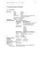
11.1 Technical Data
Dimensions:
Width:
Depth:
Height:
Weight:
Power supply:
195 mm
200 mm
75 mm
785g
External mains adapter, Model SA125A0735U-S (Sino-American)
Input: 100-240 V AC, 50/60 Hz
Output: 7.5 V DC, 3000 mA
Consumption:
Operating: max.3 Watt
System description:
Type: reflectance photometer
Light source: LEDs (light emitting diodes)
Wavelengths:
528 nm (green)
Reader head:
CCD with a 320*90 useful resolution
Sample:
80 µl capillary blood or serum
(two drop of regular volume)
Measuring and
displayed range:
<3ng/ml
3-5ng/ml
5-10ng/ml
10-20ng/ml
>20ng/ml
Measuring cycle: approx. 60 sec (serial measure)
Max. throughput: 60 Dipstick/hour (serial measure)
Printer:
thermal printer
Display:
liquid crystal display, 2 lines of 24
characters
Memory:
26 samples
Date, time: integrated clock
Operating / Storage
conditions:
In operating
In storage
Temperature:
+15 ° to + 30 °C
-20 ° to + 70 °C
Relative humidity:
20 % to 80 %
20 % to 85 %
Optimum operating conditions:
Temperature:
+ 20 ° to + 26 °C
Relative humidity:
30 % to 60 %
Interfaces:
PC/HOST:
RS 232, D-Sub socket, 9-pin, female, unidirectional
AT/PC keyboard: 6-pin PS2 socket, female
READSENSOR INSTRUCTIONS
-
Version 1.3
December 2007
37 - 38
11.2 Safety Notices
Readsensor meets the requirements of the European Directive 98/79/EC on in vitro
diagnostic medical devices. Furthermore, this analyzer was designed and
manufactured to comply with international standard IEC 1010-1, "Safety
requirements for electrical equipment for measurement, control and laboratory use,
part 1: general requirements" and left the factory in a safe condition. This
international standard is equivalent to the standards UL 3101-1 for the USA, CSA
C22.2 No. 1010.1 for Canada and EN 61010-1 for EU.
The Readsensor fulfils the requirements of the EMC Directive on electromagnetic
compatibility.
This product fulfils the requirements of Directive 98/79/EC on in vitro diagnostic
medical devices.
In order to keep your instrument in a perfect and safe condition, it is up to the user to
observe all instructions and warnings included in this manual.
The instrument must only be operated with the prescribed power supply unit (Class II
protection).
Opening covers or removing parts of the instrument, except where this can be
achieved manually without the use of any tools, may expose voltage-carrying
components. Connectors can be live, too. Never try to maintain or repair an
open instrument, which is carrying voltage.
If you suspect that the instrument can no longer be operated safely, turn it off and
take steps to ensure that no one will subsequently attempt to use it. Make sure that
only trained members of staff operate the Readsensor analyzer.
Any personal computer to which the analyzer is connected must meet the EN 60950
requirements for data processing equipment.
ATTENTION: The data and information contained in this manual are accurate
at the time of going to press. Any substantial changes will be incorporated in
the next edition. In case of conflict between this manual and information given
in package inserts, the package inserts shall take precedence.
11.3 Manufacturer's Warranty
Unisensor SA. warrants Readsensor against defects in materials and workmanship
for a period of one year from the date of purchase. The warranty ceases to apply if
the instrument has been misused, poorly maintained or tampered with. Liability
under this warranty is limited to the repair of defective parts or, at the discretion of
Unisensor SA., to the issue of a replacement instrument. A right to rescind the
purchase agreement only exists if the replacement instrument is also found to be
defective. Claims other than these will not be entertained.
Damage caused by misuse, maltreatment, tampering, human error and extreme
force are excluded from this warranty.
This warranty is only valid if the date, and the stamp and signature of the dealer are
entered on the warranty card on the date of purchase.
The warranty period is not extended by any claim made under this warranty.
READSENSOR INSTRUCTIONS
-
Version 1.3
December 2007
38 - 38
Readsensor developed for Unisensor SA. By :
77 ELEKTRONIKA Kft
1116 Budapest, Fehérvári út 98.
HUNGARY
Tel: + 36 1 206 - 1480
Fax: + 36 1 206 - 1481
E-mail: [email protected]
IVD
UNISENSOR S.A.
Z.I. du DOSSAY
3, rue du DOSSAY
BELGIUM
Tel : + 32 42 52 66 02
Fax : + 32 42 52 90 55
E-mail : [email protected]
for professional use
REF
RAC-9903-1
CE
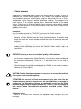
The following symbols are used throughout this document
Symbols/Signs
Explanation
WARNING/CAUTION: Indicates a potentially hazardous
situation that if not avoided could result in personal injury or
damage to the instrument. This symbol is also used to highlight
situations that can compromise results.
BIOHAZARD: Indicates a potentially dangerous situation
involving the presence of biohazardous material. All safety
precautions must be taken to prevent personal injury or damage
to the equipment.
ATTENTION: Indicates special problems or important
information. Read the accompanying text carefully.
IVD
In Vitro Diagnosticum
CE
98/79/EC IVD directive, Readsensor equipment
Consult instructions for use
SN
Serial No.
Manufacturer
REF
Catalog No.
Service Records:
Last modification: 25 JULY 2006. v1.2.