1
Cat. No. V093-E1-05
NS-Runtime Software
USER’S MANUAL
Notice
OMRON products are manufactured for use according to proper procedures by a
qualified operator and only for the purposes described in this manual.
! DANGER
The following conventions are used to indicate and classify precautions in this manual.
Always heed the information provided with them. Failure to heed precautions can
result in injury to people or damage to property.
Indicates an imminently hazardous situation which, if not avoided, will result in death or
serious injury. Additionally, there may be severe property damage.
! WARNING Indicates a potentially hazardous situation which, if not avoided, could result in death or
serious injury. Additionally, there may be severe property damage.
! Caution
Indicates a potentially hazardous situation which, if not avoided, may result in minor or
moderate injury, or property damage.
OMRON Product References
All OMRON products are capitalized in this manual. The word "Unit" is also capitalized when
it refers to an OMRON product, regardless of whether or not it appears in the proper name of
the product.
The abbreviation "Ch," which appears in some displays and on some OMRON products,
often means "word" and is abbreviated "Wd" in documentation in this sense.
The abbreviation "PLC" means Programmable Controller.
The abbreviation "host" means a controller, such as an IBM PC/AT or compatible computer,
that controls a PT (Programmable Terminal).
Visual Aids
The following headings appear in the left column of the manual to help you locate different
types of information.
Indicates information of particular interest for efficient and convenient operation
Note
of the product.
1, 2, 3...
1. Indicates lists of one sort or another, such as procedures, checklists, etc.
OMRON, 2007
All rights reserved. No part of this publication may be reproduced, stored in a retrieval system, or transmitted, in any form, or by
any means, mechanical, electronic, photocopying, recording, or otherwise, without the prior written permission of OMRON.
No patent liability is assumed with respect to the use of the information contained herein. Moreover, because OMRON is
constantly striving to improve its high-quality products, the information contained in this manual is subject to change without
notice. Every precaution has been taken in the preparation of this manual. Nevertheless, OMRON assumes no responsibility for
errors or omissions. Neither is any liability assumed for damages resulting from the use of the information contained in this
publication.
1
Contents
Notice
..............................................................................................................................................1
About this Manual .......................................................................................................................................5
Related Manuals ..........................................................................................................................................6
Terminology ..............................................................................................................................................8
Introduction ..............................................................................................................................................9
Application Precautions.............................................................................................................................10
Section 1
Overview .................................................................................................. 1-1
1-1 About this manual............................................................................................................................ 1-2
1-2 About NS-Runtime .......................................................................................................................... 1-3
1-2-1 NS-Runtime features............................................................................................................ 1-3
1-2-2 NS-Runtime Specifications.................................................................................................. 1-4
1-2-3 System Configuration .......................................................................................................... 1-5
1-3 CX-Designer Menu List .................................................................................................................. 1-6
1-4 Comparison between the NS Series and the NS-Runtime ............................................................... 1-8
Section 2
Setting up, Starting up and Exiting the NS-Runtime ......................... 2-1
2-1 Preparations for Installation............................................................................................................. 2-2
2-2 Installing the NS-Runtime ............................................................................................................... 2-3
2-2-1 Installation Procedure .......................................................................................................... 2-3
2-3 Uninstallation Procedure ................................................................................................................. 2-5
2-4 Starting the NS-Runtime ................................................................................................................. 2-6
2-4-1 Starting the NS-Runtime from the NSA Series.................................................................... 2-6
2-4-2 Starting the NS-Runtime from an environment other than the NSA Series ......................... 2-6
2-5 Ending the NS-Runtime................................................................................................................... 2-7
2-6 User Interface .................................................................................................................................. 2-9
Section 3
Creating Projects .................................................................................... 3-1
3-1 Creating Projects ............................................................................................................................. 3-2
3-1-1 Creating New Projects ......................................................................................................... 3-2
3-1-2 Project Property settings ...................................................................................................... 3-3
3-2 System Settings ............................................................................................................................... 3-4
3-2-1 PT Operations ...................................................................................................................... 3-4
3-2-2 Initial Tab Page .................................................................................................................... 3-6
3-2-3 History Tab Page.................................................................................................................. 3-7
3-2-4 Printer Tab Page................................................................................................................... 3-8
3-2-5 Video Tab Page.................................................................................................................... 3-8
3-2-6 Maximum Screen Size Tab Page ......................................................................................... 3-8
3-2-7 Function Keys ...................................................................................................................... 3-9
3-3 Communications Settings .............................................................................................................. 3-10
3-3-1 Serial Port A / Serial Port B ............................................................................................... 3-10
3-3-2 Ethernet.............................................................................................................................. 3-11
3-3-3 Controller Link................................................................................................................... 3-12
3-4 Creating Screens............................................................................................................................ 3-13
3-4-1 Creating New Screens........................................................................................................ 3-13
3-4-2 Screen Properties Setting ................................................................................................... 3-13
2
3-5 Converting Projects ....................................................................................................................... 3-14
Section 4
NS-Runtime Functions ........................................................................... 4-1
4-1 System Memory............................................................................................................................... 4-2
4-1-1 System Bit Memory ($SB)................................................................................................... 4-2
4-1-2 System Word Memory ($SW) ............................................................................................. 4-5
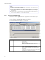
4-2 Document Display ........................................................................................................................... 4-7
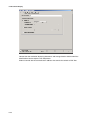
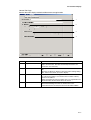
4-2-1 Document Table Setting....................................................................................................... 4-8
4-2-2 Document Display................................................................................................................ 4-9
4-3 Alarm/Event Setting ...................................................................................................................... 4-15
4-4 Data Logs ...................................................................................................................................... 4-16
4-5 Macros ........................................................................................................................................ 4-17
4-5-1 Functions............................................................................................................................ 4-17
4-5-2 Details of the Functions ..................................................................................................... 4-20
Section 5
NS-Runtime System Menu Operations ................................................ 5-1
5-1 Displaying and Exiting the System Menu ....................................................................................... 5-2
5-1-1 Displaying the System Menu ............................................................................................... 5-2
5-1-2 Exiting the System Menu..................................................................................................... 5-3
5-2 System Menu Configuration............................................................................................................ 5-4
5-3 Special Screen ................................................................................................................................. 5-5
5-3-1 Alarm History ...................................................................................................................... 5-5
5-3-2 Operation Log ...................................................................................................................... 5-6
5-3-3 Error Log.............................................................................................................................. 5-7
5-3-4 Communication Test ............................................................................................................ 5-9
5-3-5 Version Display ................................................................................................................. 5-10
5-4 Transferring Data........................................................................................................................... 5-11
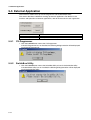
5-5 External Application...................................................................................................................... 5-12
5-5-1 CX-Programmer................................................................................................................. 5-12
5-5-2 SwitchBox Utility .............................................................................................................. 5-12
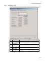
5-6 Initialization/Setting Screen .......................................................................................................... 5-13
5-6-1 Initializing Data ................................................................................................................. 5-15
5-6-2 PT Operations .................................................................................................................... 5-25
5-6-3 Project Settings .................................................................................................................. 5-30
5-6-4 Setting Passwords .............................................................................................................. 5-34
5-6-5 Communications Settings .................................................................................................. 5-37
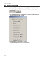
5-7 System Language........................................................................................................................... 5-44
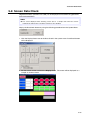
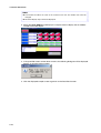
5-8 Screen Data Check ........................................................................................................................ 5-45
5-9 Numeral & String Input Mode....................................................................................................... 5-47
5-10 Exit
........................................................................................................................................ 5-48
5-10-1 End NS-Runtime ................................................................................................................ 5-48
5-10-2 Shut Down ......................................................................................................................... 5-48
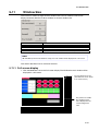
5-11 Window Size ................................................................................................................................. 5-49
5-11-1 Full screen display ............................................................................................................. 5-49
5-11-2 Maximize ........................................................................................................................... 5-50
5-11-3 Minimize ............................................................................................................................ 5-50
5-11-4 Show Window.................................................................................................................... 5-51
3
Section 6
Transferring Project Data...................................................................... 6-1
6-1 Transfer Methods............................................................................................................................. 6-2
6-2 Transferring Data Using a Memory Card ........................................................................................ 6-3
6-2-1 Downloading the Project Data ............................................................................................. 6-4
6-2-2 Uploading the Project Data .................................................................................................. 6-7
6-3 Transferring Data from the CX-Designer...................................................................................... 6-11
Section 7
Troubleshooting ....................................................................................... 7-1
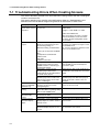
7-1 Troubleshooting Errors When Creating Screens ............................................................................. 7-2
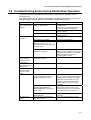
7-2 Troubleshooting Errors during NS-Runtime Operation................................................................... 7-3
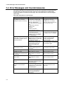
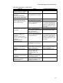
7-3 Error Messages and Countermeasures............................................................................................. 7-4
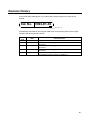
Revision History .......................................................................................................... R-1
4
About this Manual
This manual provides important information on using the NS-Runtime Software. Please read and be sure you
understand this manual before attempting to use the NS-Runtime Software, and keep this manual in a safe
place where it is accessible for future reference.
Section 1 Overview
This section provides an overview of the NS-Runtime including the functions, features, connection types and
communication methods.
A comparison between NS-Runtime and the NS Series is also described.
Section 2 Setting up, Starting up and Exiting the NS-Runtime
The NS-Runtime is application software that runs on Microsoft Windows XP, Vista, or 7.
This section describes how to install the NS-Runtime on Windows XP, Vista, or 7. It also describes methods of starting
and exiting the NS-Runtime.
Section 3 Creating Projects
This section describes procedures for creating projects, system settings, communications settings and creating
screens for the NS-Runtime.
Section 4 NS-Runtime Functions
This section describes the NS-Runtime functions.
It mainly describes functions that are added or changed from the NS Series and the CX-Designer, and does not
describe functions equivalent to those of the NS Series and the CX-Designer.
For NS Series and CX-Designer functions that this manual does not describe, refer to each manual mentioned in 1-1
About This Manual.
Section 5 NS-Runtime System Menu Operations
This section describes the basic methods for operating the System Menu of the NS-Runtime and details on functions.
Section 6 Transferring Project Data
This section describes how to send created or modified screen data to the NS-Runtime environment including the NSA
Series and to register them. It also describes how to read data registered in the NS-Runtime.
Section 7 Troubleshooting
This section describes the countermeasures for errors that may occur when creating projects with the CX-Designer or
operating them with the NS-Runtime.
This section explains errors specific to the NS-Runtime. For information on other errors, refer to 5 Troubleshooting and
Maintenance in the NS Series Programming Manual.
WARNING Failure to read and understand the information provided in this manual may result in
personal injury or death, damage to the product, or product failure. Please read each
section in its entirety and be sure you understand the information provided in the section
and related sections before attempting any of the procedures or operations given.
5
Related Manuals
The following manuals are related to the NS-Runtime Software. (The boxes at the end of the
catalog numbers indicate the revision code.)
This
manual
NS-Runtime Software User’s Manual ............................................V093-E1-@
Describes installing the NS-Runtime Software, basic operations, and the user
interface. It also describes special features and application methods of the
NS-Runtime Software.
CX-Designer User’s Manual .......................................................V099-E1-@
Describes installing the CX-Designer, basic operations, and the user interface. It also
describes special features and application methods of the CX-Designer.
CX-Designer Online Help
Online help can be used to display CX-Designer operating procedures, settings, and
other information on-screen, including detailed setting methods for functional objects
and graphics.
NS Series Programming Manual.................................................V073-E1-@
Describes the functions and application methods of NS-series PTs. It also provides
troubleshooting methods for problems that might occur with the PT.
NS Series -V1/-V2 Setup Manual ...............................................V083-E1-@
Provides information on NS-series version 1 and version 2 PTs (i.e., the NS15-V2,
NS12-V1/V2, NS10-V1/V2, NS8-V1/V2, and NS5-V1/V2). It describes how to install
and connect a PT, provides basic specifications, and provides other hardware
information on the PTs.
NS Series Setup Manual.............................................................V072-E1-@
Provides information on NS-series PTs prior to version 1 (i.e., the NS15-V2, NS12,
NS10, and NS7).
CXONE-AL@@C-V4/AL@@D-V4 CX-One Setup Manual
...............................................................................................W463-E1-@
Provides an overview of and describes how to install the CX-One FA Integrated Tool
Package.
CX-Designer Introduction Guide....................................................V089-E1-@
This tutorial describes the procedures for creating and operating simple screens as an
example for first users of NS-series PTs.
6
Macro Reference (Installed from the CX-Designer’s CD-ROM)
The online help of the CX-Designer provides detailed information on the macro
function of NS-series PTs. PDF data containing the same contents is installed on the
hard disk when the CX-Designer is installed. Use either the online help or this PDF
data as required.
PLC Operation Manuals
Refer to the operation manuals for the CPU Unit, Special I/O Units, CPU Bus Units,
Communications Units, and other PLC Units that you are using to obtain information
on PLC operation and functions.
7
Terminology
The following terminology is used in this manual.
8
NS-Runtime
Indicates OMRON’s NS-Runtime Software (NS-NSRCL@ @ ).
NS-series PT
Indicates a Programmable Terminal in OMRON’s NS Series of Programmable Terminals.
PLC
Indicates an OMRON Programmable Controller.
Host
Indicates the PLC, IBM PC/AT or compatible computer, or personal computer controlling an
NS-series PT.
CX-One
Indicates OMRON’s CX-One Integrated FA Tool Package
(CXONE-AL@ @ C-V4/AL@ @ D-V4). This package contains the Support Software for most
OMRON PLCs and Components.
CX-Designer
Indicates the OMRON CX-Designer (NS-CXDC1-V@ ).
Introduction
The NS-Runtime Software provides the same functionality as an NS-series Programmable
Terminal to enable implementing FA onsite information displays and operations on Windows
XP, Vista, or 7. To enable using the NS-Runtime Software correctly, be sure you have
sufficient understanding of the CX-Designer and Programmable Terminal functions and
characteristics. Refer to all related manuals when using the NS-Runtime Software.
• Intended Audience
This manual is intended for the following personnel, who must also have knowledge of
electrical systems (an electrical engineer or the equivalent).
• Personnel in charge of introducing FA systems into production facilities.
• Personnel in charge of designing FA systems.
• Personnel in charge of installing and connecting FA systems.
• Personnel in charge of managing FA systems and facilities.
• Installation Environment
The NS-Runtime operates on an open platform, and usage conditions differ from those of
NS-series PTs.
• Never use the NS-Runtime for an FA system that operates 24 hours a day.
• OMRON disclaims responsible for any problems caused by using the NS-Runtime with
other software applications or any problems caused by the installation environment.
• It is the user's responsibility to isolate causes of any problems caused by other
software applications or by the installation environment.
9
Application Precautions
10
•
For information on device connections and settings for a computer where the NS-Runtime is
installed, also refer to NS-V1/V2 series Programmable Terminals Setup Manual V083-E1-@.
•
Use this product under Windows general specifications.
•
When unpacking the product, check the CD and the dongle carefully for any damages.
•
Do not install unnecessary applications in a computer where the NS-Runtime is installed.
•
Exit all applications that are not directly related to the NS-Runtime.
•
Disable sharing hard disks, printers or other devices with other computers on any network.
•
Some notebook computers set the RS-232C port to modem or infrared line by default. Change
the settings according to the operating instructions for your computer so that the RS-232C port
can be used as a normal serial port.
•
Some notebook computers set the RS-232C port not to supply rated power to the port to save
energy by default. There are Windows settings and also possibly settings for computer specific
utilities or BIOS settings for power saving. Disable the settings according to the operating
instructions for your computer to provide power to the port.
•
The whole systems may stop depending on the way the NS-Runtime started/ended. Follow the
procedure to start/end the NS-Runtime.
•
Start actual system application only after sufficiently checking screen data, macros, and the
operation of the program in the host.
•
Include programming that regularly accesses the RUN signal and confirms that the NS-Runtime
is operating normally.
•
Confirm the safety of the system before pressing touch switches.
•
Do not accidentally press touch switches when the backlight is not lit or when the display does
not appear.
•
Signals from the touch switches may not be input if the switches are pressed consecutively at
high speed. Confirm each input before proceeding to the next one.
•
Before initializing screen data, confirm that existing data is backed up at the CX-Designer.
•
When changing the password with the system menu, do not reset or turn OFF the power supply
until writing is finished (i.e., until the Write Button returns to its original condition). It may become
impossible to manipulate screens if the password is not set correctly.
•
Do not attempt to disassemble, repair, or modify the product in any way.
•
Dispose of the product according to local ordinances as they apply.
Read and Understand this Manual
Please read and understand this manual before using the product. Please consult your OMRON
representative if you have any questions or comments.
1. WARRANTY
1) The warranty period for the Software is one year from either the date of purchase or the date on
which the Software is delivered to the specified location.
2) If the User discovers defect of the Software (substantial non-conformity with the manual), and
return it to OMRON within the above warranty period, OMRON will replace the Software without
charge by offering media or download from OMRON’s website. And if the User discovers defect
of media which is attributable to OMRON and return it to OMRON within the above warranty
period, OMRON will replace defective media without charge. If OMRON is unable to replace
defective media or correct the Software, the liability of OMRON and the User’s remedy shall be
limited to the refund of the license fee paid to OMRON for the Software.
2. LIMITATION OF LIABILITY
1) THE ABOVE WARRANTY SHALL CONSTITUTE THE USER’S SOLE AND EXCLUSIVE
REMEDIES AGAINST OMRON AND THERE ARE NO OTHER WARRANTIES, EXPRESSED
OR IMPLIED, INCLUDING BUT NOT LIMITED TO, WARRANTY OF MERCHANTABILITY OR
FITNESS FOR PARTICULAR PURPOSE. IN NO EVENT, OMRON WILL BE LIABLE FOR ANY
LOST PROFITS OR OTHER INDIRECT, INCIDENTAL, SPECIAL OR CONSEQUENTIAL
DAMAGES ARISING OUT OF USE OF THE SOFTWARE.
2) OMRON SHALL HAVE NO LIABILITY FOR DEFECT OF THE SOFTWARE BASED ON
MODIFICATION OR ALTERNATION TO THE SOFTWARE BY THE USER OR ANY THIRD
PARTY.
3) OMRON SHALL HAVE NO LIABILITY FOR SOFTWARE DEVELOPED BY THE USER OR ANY
THIRD PARTY BASED ON THE SOFTWARE OR ANY CONSEQUENCE THEREOF.
4) The USB dongle provided with the NS-Runtime uses the Advanced Encryption Standard (AES).
As a result, domestic laws may define the USB dongle as a cryptogram decoder and may place
restrictions on the import, export, use, and sale of the USB dongle. Before you import or export
the USB dongle, or before you use or sell the USB dongle outside of the country of purchase,
confirm if domestic laws stipulate any restrictions.
3. APPLICABLE CONDITIONS
• USER SHALL NOT USE THE SOFTWARE FOR THE PURPOSE THAT IS NOT PROVIDED IN
THE ATTACHED USER MANUAL.
• The user must operate the product according to the general specifications.
• Do not use the PT touch switch input functions for applications where danger to human life or
serious property damage is possible, or for emergency switch applications.
• Before using the product under the following conditions, make sure that the ratings and
performance characteristics of the product are sufficient for the systems, machines and
equipment, and be sure to provide them with a fail-safe circuit, and consult your OMRON
representative.
1) Using the product under conditions or environments, which are not described in the manual.
2) Applying the product to nuclear control systems, railroad systems, aviation systems, vehicles,
combustion systems, medical equipment, amusement machines, safety equipment, and other
systems, machines and equipment.
3) Using the product for any purposes that may have a serious influence on lives and property,
and requires special safety considerations.
• This manual provides information for connecting and setting up an NS-Runtime. Be sure to read
this manual before attempting to use it and keep this manual close at hand for reference during
installation and operation.
11
4. CHANGE IN SPECIFICATION
The software specifications and accessories may be changed at any time based on improvements
and other reasons.
5. EXTENT OF SERVICE
The license fee of the Software does not include service costs, such as dispatching technical staff.
6. ERRORS AND OMISSIONS
The information in this manual has been carefully checked and is believed to be accurate; however,
no responsibility is assumed for clerical, typographical, or proofreading errors, or omissions.
12
Section 1
Overview
This section provides an overview of the NS-Runtime including the functions, features,
connection types and communication methods.
A comparison between NS-Runtime and the NS Series is also described.
1-1 About this manual ............................................................................................................... 1-2
1-2 About NS-Runtime ............................................................................................................. 1-3
1-3 CX-Designer Menu List...................................................................................................... 1-6
1-4 Comparison between the NS Series and the NS-Runtime .................................................. 1-8
1-1 About this manual
1-1 About this manual
This manual describes specifications and the system configuration of the NS-Runtime and
screen creation methods using the CX-Designer.
This manual also explains added and modified functions from the existing NS Series and
CX-Designer. However, functions equivalent to those of the NS Series and the CX-Designer
are not explained in this manual.
For functions of the NS Series and the CX-Designer that are not described in this manual,
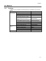
please refer to documents including the documents listed in the table below.
Document
NS Series Programming Manual
Host Connection Manual (Host Link)
Macro Reference
CX-Designer Online Help
1-2
Manual No.
V073-E1-@
Provided with CX-Designer
Provided with CX-Designer
Provided with CX-Designer
1-2 About NS-Runtime
1-2 About NS-Runtime
The NS-Runtime is software that provides functions equivalent to the NS Series, enables to
display information and perform operations for FA manufacturing sites and runs on Windows
XP, Vista, or 7 including the NSA Series.
1-2-1
NS-Runtime features
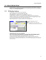
The following are the features of the NS-Runtime.
Other applications can be used at the same time.
The NS-Runtime is software that runs on Windows XP, Vista, or 7.
The NS-Runtime, therefore, can be used with other OMRON software simultaneously.
Moreover, software such as commercially available form software and applications created
by users and the NS-Runtime can be used at the same time.
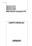
Specified applications can also be started up from the NS-Runtime.
Other applications can be
overlapped on the screen data,
and they can be used at the same time.
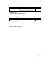
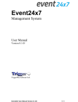
Specified document file can be displayed
With the NS-Runtime, a specified PDF file can be displayed at the timing when an alarm
occurs or at a specified timing. Therefore, for example, a PDF file that describes alarm’s
causes and countermeasures can be displayed when an alarm occurs.
Furthermore, because specified applications can be started up from the NS-Runtime,
document data created with those applications and an NS-Runtime project can be displayed
at the same time.
1-3
1-2 About NS-Runtime
Displays a PDF file on a screen
N
Noottee
To display the PDF file, Adobe Reader version 7.0 or higher must be installed in the
operating environment of the NS-Runtime Software.
1-2-2
NS-Runtime Specifications
NS-Runtime Specifications are listed below.
Item
Screen size
Connection method with host
Project data version
Specifications
NSA Series:
1024 x 768 dots max.
Other than NSA Series:
3840 x 2400 dots max.
Host Link, Ethernet, Ethernet /IP, Controller Link and
Toolbus
Versions 6.6 to 8.1 are supported.
N
Noottee
Communications with non-OMRON PLCs are not supported.
Methods for connecting to the Host, 1:1 NT Link and 1:N NT Links (Standard, High-Speed)
are not supported.
The NS-Runtime has functionality basically equivalent to that of NS-series PTs. There are
some differences, however, depending on differences between the PT and the NS-Runtime
environment, including operating system.
We recommend using the NS-Runtime with Ethernet.
1-4
1-2 About NS-Runtime
1-2-3
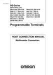
System Configuration
This section describes the system configuration used for the NS-Runtime.
The NS-Runtime runs on Windows XP, Vista, or 7 and the NSA Series.
Host
Twisted- pair cable
Keypad, Mouse
RS-232C cable (15 m max.)
RS-422A cable (500 m max.)
RS-232C/422A Adapter
Ethernet cable
Controller Link
Interface Unit
Enables Controller Link
communications with a
host.
Personal computer
Computer running
Windows
Personal computer
Computer running Windows
Bar Code Reader
Reads bar codes as
text string data.
NS-Runtime
CX- Designer
Printer
Printer that can be used
with Windows
NSA Series and
NS-Runtime
Data Transfer via
Memory Card
N
Noottee
The computer must support RS-442A to be able to connect using RS-422A.
1-5
1-3 CX-Designer Menu List
1-3 CX-Designer Menu List
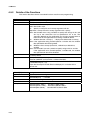
The NS-Runtime has the following pull-down menus that are different from CX-Designer’s.
Menus not described here are the same as the existing CX-Designer’s menus.
File Menu
There are following changes in the File Menu.
Item
New project
Print
Data Transfer Security
Function
Creates new projects. The NSA12/15-TX01[] and
the NS-Runtime are added.
Select the NS-Runtime when using the NSRuntime in an environment other than NSA Series.
Document Table Setting is added to the Print Item
Details.
This menu cannot be used.
Reference
3-1
−
−
• Edit Menu
There is no change in the Edit Menu.
• Find Menu
There is no change in the Find Menu.
• View Menu
There is a following change in the View Menu.
Item
Show Touch Points
Function
This menu cannot be used.
Reference
−
• PT Menu
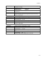
There are following changes in the PT Menu.
Item
Transfer
Reference
6-1
System Setting
The following changes are made.
-A folder can be specified to save history data.
-Maximum screen size can be set.
Registers and modifies the alarm/event.
3-2
Alarm/Event Setting
Setting items for the display document table are
added, which enables to show on a document
display object when an alarm occurs.
Always logging can be set up to 160,000 points.
Registers document files (PDF files) to display on
document display objects.
Setting ranges were changed as follows.
-NSA Series: 1024 x 768 dots max.
-Other than NSA Series: 3840 x 2400 dots max.
4-3
Data Log Setting
Document Table Setting
Screen/Sheet Properties
1-6
Function
When the CX-Designer and NS-Runtime is
installed in the same environment, a function to
copy project data to the NS-Runtime project
storage folder will be added.
Sets an NS-Runtime’s parameter operating.
4-4
4-2-2
3-4
1-3 CX-Designer Menu List
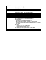
• Functional Objects Menu
There are the following changes in the Functional Objects Menu.
Item
Video Display
Document Display
Function
This menu cannot be used.
This is a newly added functional object that
displays specified document files (PDF files).
Select this Document Display to start creating.
Reference
−
4-2
• Fixed Objects Menu
There is no change in the Fixed Objects Menu.
• Tools Menu
There is the following change in the Tools Menu.
Item
Convert
Function
The PT model can be converted between NSseries PT projects and NS-Runtime projects.
Reference
3-5
• Window Menu
There is no change in the Window Menu.
• Help Menu
There is no change in the Help Menu.
1-7
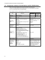
1-4 Comparison between the NS Series and the NS-Runtime
1-4 Comparison between the NS Series and the NS-Runtime
There are the following differences between the NS Series and NS-Runtime.
Functions may differ between when the NS-Runtime runs on the NSA Series and when it
runs on an environment other than the NSA Series.
Items related to Hardware, communications and data transfer
NS Series
Item
Resolution
Connectable
PLCs
Connection
Method to the
Host
Connection to the
Temperature
Controller
Connection to
another
company’s PLC
Connection to the
Barcode Reader
Transferring
project data to
the NS
Series/NSRuntime
1-8
NS-Runtime
Other than
NSA Series
NSA Series
1024 X 768 dots max.
(When using NS15)
Any of the following Series: C, CV, CS, CJ,
CP, or NSJ
- 1:1 NT Link
- 1:N NT Link (Standard, High-Speed)
- Ethernet
- EtherNet/IP
- Controller Link (When mounting Controller
Link I/F unit)
- Host Link
- Memory Link
1024 X 768 dots 3840 X 2400
max.
dots max.
Any of the following Series: CV,
CS, CJ, CP, or NSJ
- Ethernet
- Ethernet/IP
- Controller Link (When mounting
Controller Link I/F unit)
- Host Link
- Toolbus
Provided
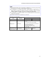
Not Provided
- Mitsubishi FX-series, A-series, and
Q/QnA-series PLCs
- SIEMENS S7-300 Series PLCs
- OMRON Trajexia Motion Controller
- Yaskawa MP-series Machine Controller
- Yaskawa Varispeed F7 Inverter or VS mini
V7 Servo Drive
- Rockwell Automation (Allen-Bradley)
SLC500, MicroLogix, PLC-5,
CompactLogix, CompactLogix, and
ControlLogix Controllers
- Devices that support Modbus RTU
- Yokogawa Electric FA-M3/FA-M3R-series
PLCs
Barcode Reader can be connected to Serial
Ports.
- Serial
- Ethernet
- Modem
- Controller Link
- USB
- Memory Card
- Data Transfer using SPMA
Not Provided
Barcode Reader can be connected
to USB Ports.
- Memory Card
- When the CX-Designer and NSRuntime is installed in the same
environment, project data that is
being edited can be copied to the
NS-Runtime’s project storage
folder using CX-Designer’s
transfer function.
1-4 Comparison between the NS Series and the NS-Runtime
N
Noottee
Data from other devices can be accessed from an application on a computer by going through
the networks. This is referred to as SPMA (Single Port Multi Access).
To communicate on a Controller Link network, a 3G8F7-CLK21-V1, 3G8F7-CLK12-V1, or
3G8F7-CLK52-V1 Controller Link Support Board must be installed in advance in the NSRuntime’s operating environment. Refer to the Controller Link Support Boards for PCI Bus
Installation Guide (Cat. No. W467) for information on mounting and setting methods.
To communicate on an Ethernet network, set the conversion table in the communications
settings of the CX-Designer.
Host Link connections are not supported for CJ2 CPU Units.
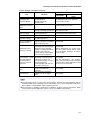
NS-Runtime Overall Operations
Item
NS Series
NSA Series
NS-Runtime
Other than NSA Series
Project Startup
Power ON
Executes the NS-Runtime
- Exits from the system menu or by operating
screen.
- Turns ON the system memory $SB63
Exiting projects
Power OFF
Inputting characters
and numerals using a
hardware keyboard
Not Supported.
The system menu has below two exit functions.
- Exits the NS-Runtime only
(Operating system will not end)
- Exits the NS-Runtime and operating system. (The
system ends.)
Possible when a
hardware keyboard is Supported.
mounted.
1-9
1-4 Comparison between the NS Series and the NS-Runtime
System Menu
Item
Displaying the system
menu
Memory card transfer
Device monitor
Displaying capture
data
PLC data trace
Starting External
Applications
Resizing window
Exit
NS Series/NSRuntime
Confirming Screen
Data
1-10
NS Series
- Press two of four corners on a
screen (For the NS15, press one of
the four corners of the touch panel
twice.)
- Start from a command button or
Multifunction Object
- Storing 4002 in $SW0
Provided.
Provided.
Provided.
Provided.
Ladder monitor and Programming
Console can start up.
Not Provided.
Not Provided.
When an address is displayed, the
allocated unit number and
communications settings can be
displayed for the SAP library.
NS-Runtime
Other than NSA
NSA Series
Series
- Double click on one of four corners.
- Start from a command button or
Multifunction Object
Provided.
The CX-Programmer and the
Switchbox Utility can start up.
Not Provided.
The CX-Programmer can start up.
The CX-Programmer and the
Switchbox Utility can start up.
Window can be resized from the
system menu.
The NS-Runtime can be exited from
the system menu.
Not Provided.
1-4 Comparison between the NS Series and the NS-Runtime
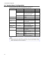
System Settings and Project Properties
Item
Changing value
of Device Monitor
Specifying a save
destination of history
data
Video
Printer Settings
Pop-up Menu
Advanced PT
operation settings
NT compatibility for
system memory
Initializing system
memory at startup
Connecting to a serial
port while ignoring
communications
errors on the other
serial port
Screen saver startup
time
Function keys
NS Series
Set whether
enable/disable to
change value from
device monitor
No specification function.
NS-Runtime
Other than NSA
NSA Series
Series
The NS-Runtime does not support the
device monitor function.
Specify a folder to save data.
Make video display settings
including selecting video board
Make settings of a printer to
connect with the PT.
Show Delimiter is supported.
Option settings are supported
for switching screens.
It is possible to select system
memory allocations compatible
with the NT-series PTs.
It is possible to select either
starting up with the previously
displayed screen and label
number, or starting up with the
startup screen set in the
system settings and the labels
set in the project properties.
It is possible to select either
displaying “Connecting” when
serial port A or B has not
connected at startup, or to go
ahead and perform
communications with only the
host that is connected.
The startup time of the screen
saver can be indirectly
specified.
The Key Status Notification
Address can be set (NS15
only)
The NS-Runtime does not support the
video display function.
No printer setting. (Printer specified with
the operating system will be used.)
No Show Delimiter function
Not Provided.
Not Provided.
Not Provided.
With the NS-Runtime, the startup screen
set in the system settings and the labels
set in the project properties are always
used at startup.
Not Provided.
With the NS-Runtime, only graphics,
labels, and other parts that do not require
communications will be displayed if serial
port A or B is not connected.
Not Provided.
Not Provided.
N
Noottee
The NS-Runtime does not support the Device Monitor. However the CX-Programmer and the
Switchbox Utility can be started up from the NS-Runtime. They can be substituted for NS Series
Device Monitor, Ladder Monitor and Programming Console.
The procedure for installing a printer driver in Windows XP differs from the NSA Series. When
using a printer with the NSA Series, please contact your OMRON representative.
1-11
1-4 Comparison between the NS Series and the NS-Runtime
Functional Objects and History Functions
Item
NS Series
NS-Runtime
NSA Series
Other than NSA Series
The Document Display Object can be used with the
NS-Runtime to display PDF files.
PDF files to be displayed can be registered in the
Document Table Setting of the CX-Designer.
Document Display
-
Video Display
Provided
Not Provided
-
PDF files (document table number) can be specified
to display on document display objects when alarms
or events occur.
Alarm/Event Settings
Data Log
Always Logging
Points:
50,000 points max.
Always Logging Points: 160,000 points max.
Macros
Item
Macro Functions
NS Series
NSA Series
NS-Runtime
Other than NSA Series
Thirty-one macro functions are added to the NSRuntime, including the module startup, string
manipulation and window manipulation.
-
SAP Library
Item
Temperature
Controllers
NS Series
-
NS-Runtime
NSA Series
Other than NSA Series
SAP Library parts that connect to Temperature
Controllers through NS direction connections are not
supported.
N
Noottee
Normal operation though SAP Library parts may not be possible if the baud rate is too slow.
Increase the baud rate if necessary.
SPMA cannot be used for the communications path when SAP Library parts are used via
EtherNet/IP.
1-12
1-4 Comparison between the NS Series and the NS-Runtime
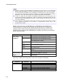
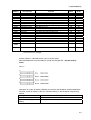
System Memory (•: Available, X: Not Available, *: Functions differ)
Item
NS Series
$SB4 (Battery Low
Notification)
NSA Series
NS-Runtime
Other than NSA Series
X
$SB6 to $SB8
(Backlight Brightness
Adjustment)
X
$SB9
(Backlight Control)
X
$SB10 (Backlight
Flash Control)
X
$SB11
(Backlight Status)
X
$SB12 to $SB 14
(Buzzer)
* Beep Sound
$SB15
(Control of Video)
X
$SB16, $SB17
(Processing Priority
Registration)
$SB20 to $SB23
(Contrast Adjustment)
$SB24 (Video
Capture)
$SB25
(Start
Printing/Capture
Screen)
$SB26(Stop Printing)
$SB27
(Test Pattern Printing)
$SB28
(Printer Head
Cleaning)
$SB29
(Update Printer
Status)
$SB30 (Printer Busy
Status/Capture Busy
Status)
$SB31(Notification of
Printer Error/Capture
Screen Error
$SB53(Prohibit
Starting
Screen Saver)
$SB63
(Exits NS-Runtime)
X
X
X
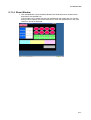
* Windows’ desktop will be captured/printed.
X
X
X
X
X
X
X
x
N
Noottee
Although HR512 to HR1535 can be accessed from the NS-Runtime, these words can be used
only for function block instances. They cannot be used in user programming.
1-13
1-4 Comparison between the NS Series and the NS-Runtime
1-14
Section 2
Setting up, Starting up and Exiting the NS-Runtime
The NS-Runtime is application software that runs on Windows XP, Vista, or 7.
This section describes how to install the NS-Runtime on Windows XP, Vista, or 7. It also
describes methods of starting and exiting the NS-Runtime.
2-1
2-2
2-3
2-4
2-5
2-6
Preparations for Installation................................................................................................ 2-2
Installing the NS-Runtime .................................................................................................. 2-3
Uninstallation Procedure..................................................................................................... 2-5
Starting the NS-Runtime..................................................................................................... 2-6
Ending the NS-Runtime...................................................................................................... 2-7
User Interface...................................................................................................................... 2-9
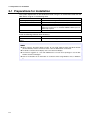
2-1 Preparations for Installation
2-1 Preparations for Installation
The system requirements for the NS-Runtime when using it in an environment other than the
NSA Series are given in the following table.
Item
Operating system (OS)
CPU
Memory
Hard disk
Disk Drive
Requirement
Windows XP SP2 or higher, Windows Vista, or Windows 7
Celeron 1.3 GHz or higher (Recommended)
512 MB minimum (Windows 7: 1 GB minimum)
Approx. 50 MB or more available space
* When the CX-Server is not installed, 280MB available space is
additionally required.
CD-ROM drive
Install the following software when necessary.
Item
Adobe Reader version 7.0 or
higher
Details
It is necessary when using the document display function.
N
Noottee
When using the document display function, do not install Adobe Acrobat and Adobe Reader
(Acrobat Reader) versions lower than version 7.0 in the NS-Runtime environment.
For details on the document display, refer to 4-2 Document Display.
You must be logged in as a user with Administrators or Power Users privileges to use the NSRuntime and the CX-Designer.
Refer to the Readme file for information on restrictions when using Windows Vista, or Windows
7.
2-2
2-2 Installing the NS-Runtime
2-2 Installing the NS-Runtime
2-2-1
Installation Procedure
Install the NS-Runtime in the hard disk.
To install the NS-Runtime, execute the installation program provided.
1. Start up Windows.
2. Close all applications before executing installation.
Place the NS-Runtime CD-ROM in the CD-ROM drive. The setup program is started
automatically.
If the setup program does not start automatically, such as after executing uninstall,
double-click the CD-ROM directory Setup.exe from Windows Explorer to execute the set
up program.
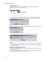
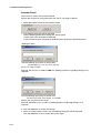
3. The NS-Runtime Setup Wizard will be displayed. Install the NS-Runtime by following the
instructions in the Setup Wizard.
4. When the Setup Wizard is running, a message confirming whether to start up the NSRuntime automatically when Windows starts up. Click the Yes Button to start up
automatically. When clicking the No Button, start up the NS-Runtime according to the
procedures described in 2-4 Starting the NS-Runtime.
2-3
2-2 Installing the NS-Runtime
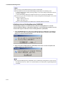
5. A message will be displayed to confirm installation of the CX-Server. Click the Yes Button.
The CX-Server will be installed. (When the CX-Server has already been installed, this
message will not be displayed.)
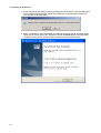
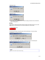
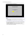
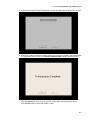
6. When installation has been completed, the following dialog box will be displayed. Select
either now or later to restart your computer and click the Finish Button. This completes
installation. Make sure to restart the computer before using the NS-Runtime.
2-4
2-3 Uninstallation Procedure
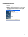
2-3 Uninstallation Procedure
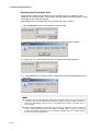
1. To uninstall the NS-Runtime, click the Windows Start Button and select Settings –
Control Panel.
2. Double-click Add/Remove Programs.
3. Select NS-Runtime_V@.@ (@.@ indicates the version number) from the list and click the
Edit/Delete Button. Follow the instructions displayed in window messages to uninstall the
NS-Runtime.
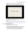
4. When uninstalling the NS-Runtime has been finished, a message will be displayed
indicating that the uninstall operation has been completed. Check the message and then
click the Finish Button.
2-5
2-4 Starting the NS-Runtime
2-4 Starting the NS-Runtime
2-4-1
Starting the NS-Runtime from the NSA Series
Turn ON the power of the NSA Series. The NS-Runtime will automatically start up and a
project that was transferred to the NSA Series will open.
N
Noottee
Refer to 6 Transferring Project Data for information on transferring project data.
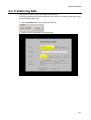
2-4-2
Starting the NS-Runtime from an environment other than the
NSA Series
If the automatic installation was selected when the NS-Runtime was installed, the NSRuntime starts up when Windows starts up. When not using the automatic startup or to start
up the NS-Runtime manually, use the following procedure.
1. To start the NS-Runtime, click the Windows Start Button, and then select Programs –
OMRON – NS-Runtime – NS-Runtime. (The displayed items may vary according to the
program folder specified during installation).
2. The NS-Runtime will start up and transferred project data will automatically opened.
N
Noottee
Connect the USB dongle provided with the NS-Runtime before starting up the NS-Runtime.
Refer to 5-4 Transferring Data for information on transferring project data.
Only one copy of the NS-Runtime application can be run at one time.
2-6
2-5 Ending the NS-Runtime
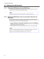
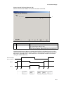
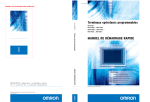
2-5 Ending the NS-Runtime
Use one of the following operations to exit the NS-Runtime.
-Exit using the system memory $SB63
-Exit from the system menu.
-Click the X Button at the top right of the main window.
-Click the NS-Runtime icon at the top left of the Main Window and select Close from the
displayed Control Menu Box.
-Click the Alt + F4 Keys at the same time.
Exiting using the system memory $SB63
If the $SB63 is turned ON, the NS-Runtime will end.
N
Noottee
A confirmation dialog box does not appear when exiting the NS-Runtime.
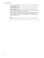
Exiting from the system menu
1. Double-click any of the four corners of the NS-Runtime main window. (Press twice in
succession when using the NSA Series.)
2. The system menu will be displayed.
Select
End NS-Runtime or
Shut Down
3. To exit the NS-Runtime, select the End NS-Runtime.
To exit the NS-Runtime and turn OFF the NSA Series, or to exit the operating system, select
Shut Down.
2-7
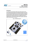
2-5 Ending the NS-Runtime
4. A confirmation message will appear. Select the Yes Button. The NS-Runtime ends.
End NS-Runtime
Shut Down
2-8
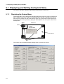
2-6 User Interface
2-6 User Interface
Main Window
Screens created with the CX-Designer will be displayed.
N
Noottee
The main window size can be set in the System Setting of the CX-Designer. For details, refer to
3-2 System Settings.
When starting up the NS-Runtime, the main window will be displayed in full screen. From the
system menu, main window size can be changed to Full screen display, Maximize, Minimize or
Show Window. For details, refer to 5-11 Window Size.
If the main window size is larger than the screen size, the screen part exceeding the window
size will be shown in a background color.
System Menu
The system menu is a menu screen to make settings for the NS-Runtime and transfer
screens. Refer to 5 NS-Runtime System Menu Operations for details.
2-9
2-6 User Interface
2-10
Section 3
Creating Projects
This section describes procedures for creating projects, system settings, communications
settings and creating screens for NS-Runtime.
3-1 Creating Projects................................................................................................................. 3-2
3-2 System Settings ................................................................................................................... 3-4
3-3 Communications Settings.................................................................................................... 3-9
3-4 Creating Screens ............................................................................................................... 3-13
3-5 Converting Projects........................................................................................................... 3-14
3-1 Creating Projects
3-1 Creating Projects
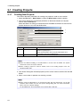
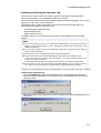
3-1-1
Creating New Projects
This section describes procedures for creating new projects in order to start creation.
1. Select the File Menu – New Project, or select the New Project under the toolbar.
2. New Project Dialog Box will be displayed. Select an NS Series Model and a System
Version. Click the OK Button.
Select the NSA12/15-TX01[] or NS-Runtime from the Model and the 6.6 or later from the
System Version to use it with the NS-Runtime.
1
2
No
Item
1
Model
2
System Version
Description
Select the NSA12/15-TX01[] or the NS-Runtime to create an NSRuntime targeted project.
Select the NS-Runtime when using the NS-Runtime in an
environment other than the NSA Series.
Select the 6.6 or later to create a project for the NS-Runtime.
N
Noottee
When the NSA12/15-TX01[] or the NS-Runtime is chosen from the Model, the System
Version 6.6 or later can only be selected.
When creating a project for other PT models, refer to the Creating Projects in the CXDesigner Online Help.
3. New Screen Dialog Box will be displayed. Input the screen number and title. Click the OK
Button.
4. When a new screen is opened, start creating a screen.
N
Noottee
When using the NS-Runtime in an environment other than the NSA Series, set the NSRuntime’s main window size from the System Setting Dialog Box. For further information,
please refer to 3-2 System Settings.
For the NSA Series, the main window size is fixed at 1024 x 768 dots.
3-2
3-1 Creating Projects
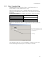
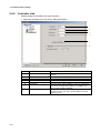
3-1-2
Project Property settings
Regarding the Project Property Dialog Box (PT Menu– Project Properties Menu), the
following settings are different from those of the NS Series.
With the NS-Runtime the Pop-Up Menu is displayed in MS Sans Serif (when the system
language is any language other than Japanese) or MS P Gothic (when the system language
is Japanese).
The relationships between font size settings with the CX-Designer and font sizes used with
the NS-Runtime are as follows.
Font size set with the CX-Designer
1x1
1x2
2x1
2x2
3x3
4x4
8x8
Font size displayed on the NS-Runtime
16 pt
24 pt
36 pt
60 pt
96 pt
Delimiter is not shown. Therefore, there is no setting for the delimiter in the Pop-up Menu Tab
Page.
Font size (pt) corresponding to the scale
set with the CX- Designer will be shown
on the NS-Runtime.
No setting
Other setting items are the same as those for the NS Series. For details on each item, refer
to the System Settings and Project Properties in the CX-Designer Online Help.
3-3
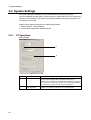
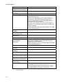
3-2 System Settings
3-2 System Settings
This section describes methods for setting the NS-Runtime Operating parameter.
Only Items different from NS Series system settings are explained here. For the setting items
common to the NS Series, please refer to the System Settings and Project Properties in the
CX-Designer Online Help.
Display System Setting Dialog Box in the following procedure.
1. Select PT Menu – System Setting.
2. System Setting Dialog Box will be displayed.
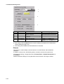
3-2-1
PT Operations
Select PT Tab.
1
2
No
3-4
Item
1
Screen Saver
2
Device Monitor,
Changing Value
Description
If the Screen Saver Active Field is set to Display Erased, the
monitor’s power supply will be turned OFF if there are no
operations on the computer, including the NS-Runtime, for the time
set in the Screen Saver Start-up Time. Also, with the NS-Runtime,
the screen saver start-up time cannot be set indirectly.
The NS-Runtime does not the support Device Monitor function.
Therefore, no setting is required for the Changing Value.
3-2 System Settings
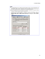
N
Noottee
The NS-Runtime does not support the Device Monitor. However, the CX-Programmer and
the SwitchBox Utility can start up from the system menu and they can be alternatively used
as functions of Device Monitor, Ladder Monitor and Programming Console.
When the NS-Runtime starts up, Windows’ Power Options setting will be changed according
to the Screen Saver settings of a project that is opened.
In order to change the power options settings after using the NS-Runtime, select the
Control Panel – Power Options from Windows. Then select the Power Options
Properties Dialog Box – Power Schemes Tab Page and change the Turn off monitor
settings.
3-5
3-2 System Settings
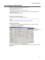
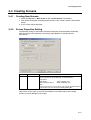
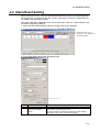
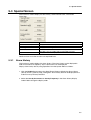
3-2-2
Initial Tab Page
Click the Initial Tab – System Memory List Button. The Initial Value for System Memory
Dialog Box will be displayed.
If these options are selected, system memory in each field will communicate with the
allocation addresses set in the Initial Tab Page.
Setting methods are the same as those for the NS Series. However, $SB that can be used
for the NS-Runtime is different from those for the NS Series. For information on the usable
$SB, refer to 4-1 System Memory.
3-6
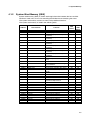
3-2 System Settings
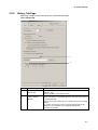
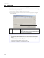
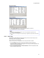
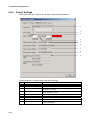
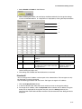
3-2-3
History Tab Page
Specifying a folder to save history data with an NS-Runtime project.
Select History Tab.
1
2
No
Item
1
Save destination of
history data
2
Set the save cycle for
Internal Holding
Memory
Description
Specify a folder to save Operation Log, Alarm History, Data Log
and Error Log.
Specify a folder of up to 160 characters.
Deselect this option to save when the NS-Runtime ends.
Select this option to save $HB/$HW status and each history data at
a specified interval.
Set the Save Cycle to between one second to 24 hours 0 second 0
minute.
No need to set the Save Cycle in a normal situation but set this
when there is a possibility of not ending the NS-Runtime
environment normally.
3-7
3-2 System Settings
N
Noottee
Saved $HB/$HW status and each logging data will be automatically read when the NSRuntime starts up next time.
A folder specified as a save destination of history data is used in the following purposes as
well.
-Destination to save BMP files created by $SB25(Screen capture).
-Destination to save data files to be used for data blocks (When the Memory Card is selected
as a destination to read/write data files).
-Destination to save files specified with READCF/WRITECF macro.
Even when the Set the ‘save cycle for Internal Holding Memory’ is specified, $HB, $HW and
history data will be saved when the NS-Runtime ends.
3-2-4
Printer Tab Page
There is no Printer Tab with an NS-Runtime project, because a printer set with Windows will
be used.
3-2-5
Video Tab Page
There is no Video Tab because the NS-Runtime does not support video display.
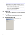
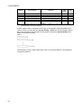
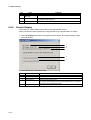
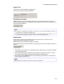
3-2-6
Maximum Screen Size Tab Page
Setting the NS-Runtime main window size in the Maximum Screen Size.
Use this function when using the NS-Runtime in non-NSA Series environments.
1
3-8
3-2 System Settings
No
1
Item
Maximum Screen Size
Details
Set the main window size of the NS-Runtime.
Width: 1 to 3,840 dots, Height: 1 to 2,400 dots
Changed screen/sheet size will be modified as follows.
3-2-7
Before change
After change
Screen/sheet for which a size exceeding the
Width/Height have been set.
Screen/sheet for which a size not exceeding the
Width/Height have been set.
The size will be changed to the Width/Height set
in the Maximum Screen Size.
The screen size will not be changed.
Function Keys
In the NS-Runtime, there are no function key tab page settings.
3-9
3-3 Communications Settings
3-3 Communications Settings
The methods for setting the communications with the host are described here.
The NS-Runtime can communicate to the host through Serial Port A or Serial Port B (Host
link, toolbus), Ethernet, and Controller Link.
1. Select the PT Menu – Communication Setting
2. Comm. Setting Dialog Box will be displayed.
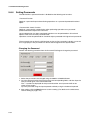
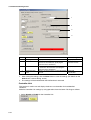
3-3-1
Serial Port A / Serial Port B
Serial Port A / Serial Port B can communicate by means of the host link and toolbus
methods.
1. Select Serial Port A and Serial Port B in the Comm. Setting Dialog Box.
1
2
3
4
5
6
7
8
9
No.
3-10
Item
1
2
3
4
5
Serial Port
Host Name
Type
Protocol
Port
6
7
Comm.
Speed
Data Bits
8
Stop Bits
9
Parity
Description
Set the PLC when using a Serial Port.
Set any host name.
Select SYSMAC-CV, SYSMAC-CS1, SYSMAC-CJ1 or SYSMAC-CJ2.
Select Host Link or toolbus.
Set a COM port name that is used for communicating in the NS-Runtime
environment.
Set 19200, 38400, 57600 or 115200 for the baud rate.
When setting Host Link for the Protocol, set 4 Bits, 5 Bits, 6 Bits, 7 Bits or 8
Bits for the data bits.
When setting Host Link for the Protocol, set 1 bit or 2 bits for the stop bit
length.
When setting Host Link for the Protocol, set Even, Odd, None, Mark or
Space for the parity bits.
3-3 Communications Settings
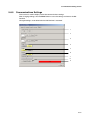
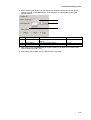
3-3-2
Ethernet
Making settings for Ethernet communications.
1. Select the Ethernet in the Comm. Setting Dialog Box.
1
2
3
4
6
7
8
No.
Item
Description
1
2
3
4
5
Ethernet
Network Address
Node Address
UDP Port No.
LAN Speed
6
IP Address
7
Conversion Table
8
Add Host
Select the Enable when communicating through Ethernet.
Set the Network Address to between 1 and 127.
Set the Node Address to between 1 and 254.
Set the UDP port number between 1024 and 65535.
Set 10/100BASE-T Auto Switch or 10BASE-T (fixed) for the speed
setting method for the Ethernet.
IP Address cannot be set with the CX-Designer.
Communications will be performed using the IP Address set in the
NS-Runtime environment.
Show a table of conversion from FINS Node Address to IP Address
when communicating through Ethernet. When using Ethernet
communications, click the Add Button and set the IP address
conversion table.
Add hosts.
Sets the host name, host type, network address and node address
for the host.
3-11
5
3-3 Communications Settings
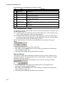
3-3-3
Controller Link
Making settings for Controller Link communications.
1. Select the Controller Link in the Comm. Setting Dialog Box.
1
2
3
4
5
6
7
No.
3-12
Item
1
Controller Link
2
3
4
5
6
Network Address
Node Address
Comm. Speed
Data Link Table Setting
Read Status
7
Add Host
Details
Select the Enable when communicating through the
Ethernet.
Set the Network Address to between 1 and 127.
Set the Node Address to between 1 and 32.
Set the baud rate (bps) to 500k, 1M or 2M.
Specify the data link table.
Select this option when reading the status of controller link.
Then set the read allocation address to a multiple of 16
within a range of $B0 to $B32336.
Add hosts.
Set the host name, host type, network address and node
address for hosts.
3-4 Creating Screens
3-4 Creating Screens
3-4-1
Creating New Screens
1. Select the File Menu – New Screen or click the New Screen in the Toolbar.
2. New Screen Dialog Box will be displayed. Set the screen number and title. Click the OK
Button.
3. A new screen will be displayed.
3-4-2
Screen Properties Setting
The following settings in the Screen Properties Dialog Box (PT-Screen/Sheet Properties)
differ from those of the NS Series. The setting range depends on the NS-Runtime
environment.
No
1
Item
Screen Size
Description
Set the screen size displayed on the NS-Runtime.
Screen size that can be set depends on the NS-Runtime
environment.
-NSA Series:
1024 x 768 (dot) max.
-Other than NSA Series:
3840 x 2400 (dot) max.
Note:
Users cannot create a screen whose size exceeds the NS-Runtime’s
main window size set in the System Setting Dialog Box.
Other Items are the same as those for the NS Series. For details refer to the Creating
Screens in the CX-Designer Online Help.
3-13
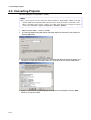
3-5 Converting Projects
3-5 Converting Projects
Converting projects to supported PT models.
N
Noottee
To convert projects from the NS Series (NS15/12/10/8/7/5, NSJ12/10/8/5, NSH5) to the NSRuntime (NSA Series and NS-Runtime), projects before conversion must be version 6.6 or later.
When converting projects whose versions are earlier than version 6.6, change the project
versions into version 6.6 or higher the Tools Menu – Convert – Version.
1. Select the Tools Menu – Convert – Model.
2. The Convert Model Dialog Box will be displayed. Select NS-Runtime as the model and
click the OK Button.
3. Messages will be displayed to confirm the functional differences between NS Series and
NS-Runtime. Check the information and if you still want to convert, click the OK Button.
4. Specify a name for the converted project in the Convert to Dialog Box. Click the Save
Button to convert the model.
3-14
3-5 Converting Projects
Model Conversion from the NS Series to the NS-Runtime or NSA Series
After the PT models are converted, the screens will be resized as listed below.
Model before
conversion
NS15
NS12
NS10
NS8
NS5-SQ/TQ
NS5-MQ
NSJ12
NSJ10
NSJ8
NSJ5-SQ/TQ
NSH5-SQ
Model after
conversion
Screen Size
NSA Series
NS-Runtime
NSA Series
NS-Runtime
NSA Series
NS-Runtime
NSA Series
NS-Runtime
NSA Series
NS-Runtime
NSA Series
Base screens will be resized to 1,024 x 768 dots.
Base screens will be resized to 3,840 x 2,400 dots.
Base screens will be resized to 1024 x 768 dots.
Base screens will be resized to 3,840 x 2,400 dots.
Base screens will be resized to 1024 x 768 dots.
Base screens will be resized to 3,840 x 2,400 dots.
Base screens will be resized to 1024 x 768 dots.
Base screens will be resized to 3,840 x 2,400 dots.
Base screens will be resized to 1024 x 768 dots.
Base screens will be resized to 3,840 x 2,400 dots.
Base screens will be resized to 1024 x 768 dots.
NS-Runtime
NSA Series
NS-Runtime
NSA Series
NS-Runtime
NSA Series
NS-Runtime
NSA Series
NS-Runtime
NSA Series
NS-Runtime
Base screens will be resized to 3,840 x 2,400 dots.
Base screens will be resized to 1024 x 768 dots.
Base screens will be resized to 3,840 x 2,400 dots.
Base screens will be resized to 1024 x 768 dots.
Base screens will be resized to 3,840 x 2,400 dots.
Base screens will be resized to 1024 x 768 dots.
Base screens will be resized to 3,840 x 2,400 dots.
Base screens will be resized to 1024 x 768 dots.
Base screens will be resized to 3,840 x 2,400 dots.
Base screens will be resized to 1024 x 768 dots.
Base screens will be resized to 3,840 x 2,400 dots.
The communications settings of the hosts of the serial port A and B will be changed as
follows.
Before Conversion
Host Type
Port Name
SYSMAC-PLC
Others
Host Link
NT Link (1:1)
NT Link (1:N)
Others
-
Comm. Speed
Data Bit
Stop Bit
Parity
-
Protocol
After Conversion
SYSMAC-CS
Cannot convert
Host Link
Cannot convert
Serial Port A : COM1
Serial Port B : COM2
19200
7
2
Even
There is no change in settings of the hosts of Ethernet and Controller Link.
For the Ethernet, however, the NS Series PT’s IP address setting will be deleted.
The NS-Runtime will communicate using the IP address set for the operating environment.
3-15
3-5 Converting Projects
N
Noottee
Although screen data for the NS5-MQ0[]-V2 is displayed in 16 grayscale levels on the CX-Designer
displays and the NS5-MQ0[]-V2 screen, the data will be displayed in color if it is converted to data
for a PT model with color displays on the CX-Designer or transferred to a PT with a color display
screen. The color codes that are used when creating the screen data for the NS5-MQ0[]-V2 will be
displayed for screen data and the image colors will be used for BMP and JPEG data.
In order to change the main window size (Maximum Window Size) of the NS-Runtime after
converting the model into the NS-Runtime, change the setting from the Maximum Screen Size Tab
Page in the System Setting Dialog Box (PT Menu – System Setting). For further information, refer
to 3-2 System Settings
Always confirm the communications settings after conversion. Then change the settings according
to the operating environment. For the details on communications settings, refer to 3-3
Communications Settings.
Model Conversion from the NS-Runtime or NSA Series to the NS Series
The NS-Runtime has functionality not supported by the NS-series PTs. Therefore, the
settings of some functions will be changed when the model is converted. It may not be
possible to convert some functions depending on the settings. It that occurs, the conversion
process will be canceled.
Function
Functions that will
have settings
changed and
converted
Conversion
Screen size
Communications
settings (serial port
A/B)
Document display
object
Document display
settings
Alarm/event
settings
System settings
Functions that may
not be converted
depending on the
setting
Data log settings
Macros
The screen size will be converted to match the specified NSseries PT. (Refer to the following table for details.)
If Host Link is set, the communications conditions will be
converted. (Refer to the following table for details.)
If Toolbus is set, it will be converted to NT Link (1:N). (Refer
to the following table for details.)
Document display objects will be deleted from the screens.
These settings will be cleared.
Any settings to display a document on a document display
object will be cleared.
The settings for the saving destination for history data will be
cleared.
The settings for the saving interval will be cleared.
Conversion will not be performed if the number of records in
the log exceeds 50,000 for a normal log.
Macros used will not be converted if they supported only by
the NS-Runtime.
After the PT models are converted, the screens will be resized as listed below.
Model before
conversion
NS-Runtime or NSA
3-16
Model after
conversion
NS15
NS12
NS10
NS8
NS5-SQ/TQ
NS5-MQ
Screen Size
Base screens will be resized to 1,024 x 768 dots.
Base screens will be resized to 800 x 600 dots.
Base screens will be resized to 640 x 480 dots.
Base screens will be resized to 640 x 480 dots.
Base screens will be resized to 320 x 240 dots.
Base screens will be resized to 320 x 240 dots.
3-5 Converting Projects
Model before
conversion
NS-Runtime or NSA
Model after
conversion
NSJ12
NSJ10
NSJ8
NSJ5-SQ/TQ
NSH5
Screen Size
Base screens will be resized to 800 x 600 dots.
Base screens will be resized to 640 x 480 dots.
Base screens will be resized to 640 x 480 dots.
Base screens will be resized to 320 x 240 dots.
Base screens will be resized to 320 x 240 dots.
The communications settings of the hosts of the serial port A and B will be changed as
follows.
Before Conversion
Host Type
Protocol
Port Name
Comm. Speed (Host Link)
Data Bits (Host Link)
Stop Bits (Host Link)
Parity (Host Link)
Comm. Speed (1:N NT Link)
Unit No. (1:N NT Link)
SYSMAC-CS1/SYSMAC-CJ1/
SYSMAC-CV/SYSMAC-CJ2
Host Link
Toolbus
COM port
19,200
38,400, 57,600, or 115,200
4 bits, 5 bits, 6 bits, 7 bits, 8 or bits
1 bit/ 2 bits
Even, Odd, None, Mark, or Space
-----
After Conversion
SYSMAC-PLC
Host Link
1:N NT Link
--19,200
9600
7 bits (fixed)
2 bits (fixed)
Even (fixed)
High speed
0
N
Noottee
The project data will be changed if you specify to convert the model to one of the following models
(if the project to be converted is a version lower than the one given in the following table).
NS model to be converted
Project data version after conversion
NS15
Ver. 8.1
NS5-@@1@-V2
Ver. 8.0
NSJ5-@@1@
Ver. 8.0
NSH5-@@1@-V2
Ver. 8.0
After the conversion, check the communications settings and make changes according to the
operating environment. For details on communications settings, refer to information on setting the
system and projects in the online help for the CX-Designer.
When the model is converted to an NS-series PT, the document table settings will be cleared, but
the set PDF files will not be deleted. The PDF files will remain in the project folder and other
specified folders. Delete the PDF files manually if they are not required.
Refer to 4-5 Macros for information on macros for NS-Runtime.
The model conversion will stop if there are items that cannot be converted to the NS-series PT. If
this occurs, the items that cannot be converted will be displayed in the Output Window. Check the
details, revise the project data so that it can be converted, and then attempt to perform model
conversion again.
3-17
3-5 Converting Projects
3-18
Section 4
NS-Runtime Functions
This section describes the NS-Runtime functions.
It mainly describes functions that are added or changed from the NS Series and the CXDesigner, and does not describe functions equivalent to those of the NS Series and the CXDesigner.
For NS Series and CX-Designer functions that this manual does not describe, refer to each
manual mentioned in 1-1 About This Manual.
4-1 System Memory .................................................................................................................. 4-2
4-2 Document Display............................................................................................................... 4-7
4-3 Alarm/Event Setting.......................................................................................................... 4-15
4-4 Data Logs .......................................................................................................................... 4-16
4-5 Macros .............................................................................................................................. 4-17
4-1 System Memory
4-1 System Memory
The NS-Runtime is provided with system memory that is used for exchanging information
between the host and the NS-Runtime, such as for controlling the NS-Runtime and notifying
the status. The system memory is divided into bit and word sections.
4-1-1
System Bit Memory ($SB)
System bit memory is used to exchange information between the host and NS-Runtime,
such as for controlling the NS-Runtime and notifying the host of NS-Runtime status, in bit
units.
The system bit memory contains 64 bits with predefined functions.
The system bit memory is listed in the following table.
Address
$SB0
$SB1
$SB2
$SB3
$SB4
$SB5
$SB6
$SB7
$SB8
$SB9
$SB10
$SB11
$SB12
$SB13
$SB14
$SB15
$SB16
$SB17
$SB18
$SB19
$SB20
$SB21
$SB22
$SB23
$SB24
$SB25
$SB26
$SB27
$SB28
$SB29
$SB30
$SB31
$SB32
$SB33
$SB34
$SB35
$SB36
$SB37
$SB38
$SB39
$SB40
4-2
Classification
Notification
Notification
Notification
Control
Notification
Control
Control
Control
Control
Control
Notification
Control
Control
Control
Control
Control
Control
Notification/Control
Notification/Control
Notification/Control
Notification/Control
Notification/Control
Notification/Control
Notification/Control
Control
Control
Function
Operation Signal (Pulse)
RUN Signal (Always ON)
Screen Switch Strobe
Prohibit Shifting to System Menu
Reserved
Numeral and Character Input Detection
Backlight Brightness Adjustment (High)
Backlight Brightness Adjustment (Medium)
Backlight Brightness Adjustment (Low)
Backlight Control (Screen Saver Start/Cancel)
Backlight Flash Control
Backlight Status
Continuous Buzzer
Short Intermittent Buzzer
Long Intermittent Buzzer
Reserved
Reserved
Reserved
Display Keypad with Temporary Input
Prohibit Input
Reserved
Reserved
Reserved
Reserved
Reserved
Start Printing/Capture Screen
Reserved
Reserved
Reserved
Reserved
Reserved
Reserved
Initialize Alarm/Event History
Save Alarm/Event History
Internal Holding Memory ($HB/$HW) Initialization
Initialize Data Log
Save Data Log
Initialize Operation Log
Save Operation Log
Log Functional Object Operation
Log Switch Screen Operation
NSA
Series
Non-NSA
Series
OK
OK
OK
OK
NO
OK
OK
OK
OK
OK
OK
OK
OK
OK
OK
NO
NO
NO
OK
OK
NO
NO
NO
NO
NO
OK
NO
NO
NO
NO
NO
NO
OK
OK
OK
OK
OK
OK
OK
OK
OK
OK
OK
OK
OK
NO
OK
NO
NO
NO
NO
NO
NO
OK
OK
OK
NO
NO
NO
OK
OK
NO
NO
NO
NO
NO
OK
NO
NO
NO
NO
NO
NO
OK
OK
OK
OK
OK
OK
OK
OK
OK
4-1 System Memory
Address
Classification
$SB41
$SB42
$SB43
$SB44
$SB45
$SB46
$SB47
$SB48
$SB49
$SB50
$SB51
$SB52
$SB53
$SB54
$SB55
$SB56
$SB57
$SB58
$SB59 to
$SB62
Control
Notification/Control
Notification/Control
Control
Notification
Notification
Notification
Notification/Control
Notification
Notification
Notification
Notification
Notification
Notification
Notification
Notification
Control
$SB63
NSA
Series
Non-NSA
Series
Log Macro Operation
Initialize Error Log
Save Error Log
Reserved
Macro Error Dialog Control
Macro Error Notification
History Processing Error Flag
Memory Card Free Space Check Flag
Stop Memory Card
Memory Card Removing Status
Periodical Data Log Save in Process Flag
Data Block Operation Complete Flag
Reserved
Password Level 1 Operable Status
Password Level 2 Operable Status
Password Level 3 Operable Status
Password Level 4 Operable Status
Password Level 5 Operable Status
Reserved
OK
OK
OK
NO
OK
OK
OK
OK
OK
OK
OK
OK
NO
OK
OK
OK
OK
OK
NO
OK
OK
OK
NO
OK
OK
OK
OK
OK
OK
OK
OK
NO
OK
OK
OK
OK
OK
NO
Exit NS-Runtime
OK
OK
Function
Note: The notification bits are not write-prohibited. Also, the system will not restore values, except
when the status has changed.
System memory is allocated to PLC areas as shown below.
Allocated Addresses for System Memory (Under CX-Designer PT – System Setting –
Initial)
$SB = m
Operations of system bit memory different from those of the NS Series are described below.
For other system bit memory, refer to 2-4 System Memory in the NS Series Programming
Manual.
System bit memory
Description
$SB4 (Battery Low)
$SB4 cannot be used with NS-Runtime.
$SB6 to $SB8 (Brightness
Adjust)
$SB6 to $SB8 function only with the NSA Series.
4-3
4-1 System Memory
System bit memory
Description
$SB9 (Backlight Control
(Screen Saver Start/Cancel))
$SB9 functions only with the NSA Series.
$SB10 (Control Backlight
Flashing)
$SB10 functions only with the NSA Series.
$SB11 (Backlight Status)
$SB11 functions only with the NSA Series.
$SB12 to $SB14 (Buzzer)
When bits $SB12 to $SB14 turn ON, the buzzer sounds
while the bit remains ON.
$SB12 starts a continuous buzzer (1 second intervals),
$SB13 starts a short intermittent buzzer (0.5 second
intervals), and $SB14 starts a long intermittent buzzer (1
second intervals, same as $SB12).
The buzzer may not stop at the same time the $SB12 to
$SB14 turn OFF, because the buzzer does not stop in the
middle of sounding.
For other operations, refer to 2-4 System Memory in the NS
Series Programming Manual.
$SB15 (Notification/Control
of Video)
$SB15 cannot be used with the NS-Runtime.
$SB16, $SB17 (Processing
Priority Registration)
$SB16 and $SB17 cannot be used with the NS-Runtime.
$SB20 to $SB23 (Contrast
Adjustment)
$SB20 to $SB23 cannot be used with the NS-Runtime.
$SB24 (Video Capture)
$SB24 cannot be used with the NS-Runtime.
$SB25 (Start Printing/
Capture Screen)
(See note.)
When $SB25 turns ON, $SB25 starts printing the screen
displayed on the desktop, or capturing and saving it as a
bitmap file in a specified folder.
For other operations, refer to 2-4 System Memory in the NS
Series Programming Manual.
$SB26 (Stop Printing)
$SB26 cannot be used with the NS-Runtime.
$SB27 (Test Pattern
Printing)
$SB27 cannot be used with the NS-Runtime.
$SB28 (Printer headcleaning
$SB28 cannot be used with the NS-Runtime.
$SB29 (Update Printer
Status)
$SB29 cannot be used with the NS-Runtime.
$SB30 (Printer Busy
Status/Capture Busy Status)
$SB30 cannot be used with the NS-Runtime.
$SB31 (Notification of Printer
Error/Capture Screen Error)
$SB31 cannot be used with the NS-Runtime.
$SB53 (Prohibit Screen
Saver Startup)
$SB53 cannot be used with the NS-Runtime.
$SB63 (Exit NS-Runtime)
$SB63 exits the NS-Runtime.
When $SB63 turns ON, the NS-Runtime ends.
When the NS-Runtime exits, the communication address
allocated to $SB63 will turn OFF automatically.
Note: Specify a folder to save bit map files in the system setting dialog box. For details, refer to 3-2-3
History Tab Page.
4-4
4-1 System Memory
4-1-2
System Word Memory ($SW)
System word memory ($SW) is used to exchange information between the host and NSRuntime in word units, such as for controlling the NS-Runtime and notifying the status.
The system word memory contains 41 items with predefined functions.
The system word memory is listed in the following table.
Address
Classification
$SW0
$SW1
$SW2
Notification/control
Notification/control
Notification/control
$SW3
Notification/control
$SW4
$SW5
Notification/control
Notification/control
$SW6
Notification/control
$SW7
$SW8
Notification/control
Notification/control
$SW9
Notification/control
$SW10
$SW11
Notification/control
Control
$SW12
$SW13
Control
$SW14
$SW15
$SW16
Notification
Notification
Notification
$SW17
$SW18
$SW19
$SW20
$SW21
Notification
Notification
Notification
Notification
Notification
$SW22
$SW23
$SW24
$SW25
$SW26
$SW27
$SW28
$SW29
$SW30
$SW31
$SW32
$SW33
$SW34
Notification
Notification
Notification
Notification
Control
Control
Control
Control
Control
Control
Control
Control
Function
Current Screen No.
Current Pop-up Screen 1 No.
Position of Pop-up Screen 1 (X
Coordinate)
Position of Pop-up Screen 1 (Y
Coordinate)
Current Pop-up Screen 2 No.
Position of Pop-up Screen 2 (X
Coordinate)
Position of Pop-up Screen 2 (Y
Coordinate)
Current Pop-up Screen 3 No.
Position of Pop-up Screen 3 (X
Coordinate)
Position of Pop-up Screen 3 (Y
Coordinate)
Current Label No.
Destination(0:Printer, 1:Memory
Card)
Reserved
Password Number for Canceling
Input Prohibition
Current Time (min, s)
Current Date and Time (Day, Hour)
Current Date and Time (Year,
Month)
Current Day (Day of the Week)
No. of Generated Alarms and Events
Generated Alarm/Event ID No.
Cancelled Alarm/Event ID No.
Alarm/Event ID of Executed
Alarm/Event Object Macro
Reserved
Macro Error No.
Macro Error Screen No.
Macro Error Object ID No.
Error Macro Execution Timing
Offset Value for Index I0
Offset Value for Index I1
Offset Value for Index I2
Offset Value for Index I3
Offset Value for Index I4
Offset Value for Index I5
Offset Value for Index I6
Offset Value for Index I7
OK
OK
OK
NonNSA
Series
OK
OK
OK
OK
OK
OK
OK
OK
OK
OK
OK
OK
OK
OK
OK
OK
OK
OK
OK
OK
OK
OK
OK
OK
OK
OK
OK
OK
OK
OK
OK
OK
OK
OK
OK
OK
OK
OK
OK
OK
OK
OK
OK
OK
OK
OK
OK
OK
OK
OK
OK
OK
OK
OK
OK
OK
OK
OK
OK
OK
OK
OK
OK
NSA
Series
4-5
4-1 System Memory
Address
$SW35
$SW36
$SW37
$SW38
$SW39
$SW40
Classification
Control
Control
Control
Notification
Notification
Control
Function
NSA
Series
NonNSA
Series
OK
OK
OK
OK
OK
OK
Offset Value for Index I8
OK
Offset Value for Index I9
OK
Data Log Group No.
OK
Data Block Error No.
OK
Authentication Level
OK
Alarm/Event History Initialization
OK
Range
Note: The notification words are not write-prohibited. In addition, the system will not restore values,
except when the status has changed.
System word memory is allocated to PLC areas as shown below. Allocated Addresses for
system memory are set under PT – System Setting – Initial from the CX-Designer. BCD or
binary data storage can be selected for each group by clicking the System Memory List
Button in the Initial Tab Page.
$SW = n
For information on the system word memory, refer to 2-4 System Memory in the NS Series
Programming Manual.
4-6
4-2 Document Display
4-2 Document Display
Document Display is a functional object used for displaying specified document files (PDF
file).
Document display object enables users to display documents including operation manuals
and production instruction on the NS-Runtime.
In order to display documents, they need to be registered in document tables beforehand.
Document files can be displayed at all-time or displayed when an alarm/event occurs.
Documents to be displayed can be switched.
Displaying when an alarm/event occurs.
Document Table
Document No.
Document File
1
A.PDF
2
B.PDF
3
C.PDF
4
D.PDF
5
E.PDF
-----
No.
1
2
3
---
Alarm/Event Setting
Address
Document No.
$B100
1
$B101
3
$B102
10
-----
$B100 ON (Alarm 1 occurs)
$B101 ON (Alarm 2 occurs)
$B100, $B101 OFF
(Alarm 1,2 cleared)
Display A.PDF
Display C.PDF
(document No. 1)
which is set with
the alarm 1.
(document No. 3)
which is set with
the alarm 2.
PDF file will be hidden
when all alarms
cleared.
Switching PDF file
Address for Indirect reference
: $W100
$W100=2
$W100=5
$W100=0
Display the B.PDF file
(document No. 2).
Display the E.PDF file
(document No. 5).
PDF file will be hidden
when 0 is specified.
4-7
4-2 Document Display
N
Noottee
In order to use the document display, Adobe Reader version 7.0 or higher must be
installed in the NS-Runtime environment.
If more than one alarm/event occurs and if a document display is set to display a
document when alarm/event occurs, a PDF file to which a higher priority has been given
will be displayed.
If numbers which are not registered are specified when setting an indirect reference for
PDF file you want to display, no document will be displayed.
4-2-1
Document Table Setting
This function is used for registering PDF files displayed on a document display object.
1. Select PT Menu – Document Table Setting with CX-Designer.
2. Document Table Setting Dialog Box will be displayed.
1
2
3
4
5
6
7
No
4-8
Item
Details
1
Document Position
Select a location to store document files you want to display.
-Project Folder
-Document Folder
When selecting the Document Folder, select any folder from
the Document Folder Path to save document files.
2
Document Folder Path
When selecting the document folder from the document
position, specify any folder to store document files.
Specify a full path to folder that exists in the NS-Runtime
environment.
Folder can be specified from the Browse For Folder Dialog
Box displayed by clicking the Browse Button.
4-2 Document Display
No
Item
Details
3
No.
Document number will be displayed.
4
Comment
Enter comments of up to 32 characters.
5
Document File
6
Add
7
Delete
Set a document file for each label.
Enter a file name directly or select a file from a file selector
that is displayed by clicking
Button.
When selecting the project folder from the document position
and selecting a document file from the file selector, the
document files will be automatically copied to the project
folder.
When selecting the document folder from the document
position or when directly entering a file name, users need to
manually copy the file to the specified folder.
Adds document numbers.
Up to 5000 numbers can be added.
Among the unused numbers, the smallest number will be
added.
Deletes selected document numbers.
N
Noottee
When setting more than 42 characters for the PDF file name, the following dialog box will be
displayed. Rename the file name (Maximum of 42 characters).
In the same way, if the specified file name contains an unusable character, a dialog box asking
you to rename will be displayed.
4-2-2
Document Display
To create a document display, select the Functional Objects Menu – Document Display,
or select
icon.
Setting Items of Functional Object Properties.
This section describes setting items displayed in the document display’s functional object
properties dialog box.
4-9
4-2 Document Display
General: Set the method of displaying documents and storage location of document files.
Size/Position: Set the object’s size and position.
External Control: Set the communication address that controls the refresh of PDF files.
4-10
4-2 Document Display
General Tab Page
Set the document display method and Document storage location
1
2
3
4
No.
Item
1
Object Comment
2
Reference
3
Indirect Reference
4
Alarm/Event Reference
Details
Set the comment for the description of pasted objects.
(Up to 32 characters. One-byte and two-byte characters are
counted as one character.)
Displays a document file whose number is set with the Document
No.
Click the Set Button to display a Document Table Setting Dialog
Box. Select a document you want to display.
Displays document files using specified communication address
as a document number. Save the document number in binary
format in the address.
When specifying a document number that is not registered in the
document table, the document will not be shown.
Displays documents whose numbers have been set in the Alarm
Event Details Dialog Box when an alarm/event occurs.
If the alarm/event is cleared, the document file will be hidden.
4-11
4-2 Document Display
Size/Position Tab Page (Extension Tab)
Set and display the size and position of the object.
1
2
No.
4-12
Item
1
Size
2
Position from the Upper
Left of
Screen/Frame/Table
Details
Set the size for the functional object.
Width: 1 to 2,560 dots
Height: 1 to 1,920 dots
Specify X and Y coordinates by the position from the upper left
of Screen/frame/table.
X coordinate: -3,839 to 3,839 dots
Y coordinate: -2,399 to 2,399 dotes
4-2 Document Display
External Control Tab Page (Extension Tab)
Set the communication address that controls the refresh of PDF file.
1
No.
1
Item
Description
Document Display Direction
Select this option to display and refresh the PDF files while the
set communication address is ON.
Deselect this option to switch the PDF files in the way specified
in the Document Display Method field in the General Tab Page.
The document display will display and refresh the PDF files in the following way by turning
ON/OFF the Document Display Direction Address. (These operations are performed when a
document is displayed when an alarm/event occurs. The operation will be the same when
setting the indirect reference.)
2
Document Display
6
Direction Address
Alarm 1
Alarm 2
1
5
3
4
4-13
4-2 Document Display
1. PDF file will not be displayed even if an alarm 1 occurs, because the Document Display
Direction Address is OFF.
2. PDF file specified with the alarm 1 will be displayed, because the Document Display
Direction Address turns ON.
3. PDF file specified with the alarm 2 will be displayed, because the Document Display
Direction Address is ON.
4. PDF file will not be refreshed even if an alarm 2 cleared, because the Document Display
Direction Address is OFF. (PDF file will not be hidden.)
5. PDF file will not be refreshed even if an alarm 1 occurs, because the Document Display
Direction Address is OFF. (PDF file that is set for the alarm 1 will not be displayed.)
6. PDF file specified with the alarm 1 will be displayed, because the Document Display
Direction Address turns ON.
N
Noottee
Even if the Document Display Direction Address turns OFF, the PDF file will not be hidden.
4-14
4-3 Alarm/Event Setting
4-3 Alarm/Event Setting
When alarm/event occurs, PDF files specified with Document Display can be displayed with
the NS-Runtime. In response to this new function, setting items to specify a desired PDF file
are added to the Alarm/Event Details.
This section describes added items only. For the other items, refer to 2-14 Alarm/Event in the
NS Series Programming Manual.
1. Select the Alarm/Event Setting under the PT Menu with the CX-Designer.
2. Alarm Event Dialog Box will be displayed. Click the Add or Edit Button.
Displays whether or not a
document is set to display and
document numbers.
3. Alarm/Event Details Dialog Box will be displayed.
1
No.
1
Item
Description
Display the document on
a document display
object
Select this check box to display PDF file on a document display
object when an alarm/event occurs.
Click the Set Button to display the Document Table Setting
Dialog Box. Then select a document to display.
4-15
4-4 Data Logs
4-4 Data Logs
With the NS-Runtime, maximum number of always logging points has been extended to
160,000 points.
This section describes only the extended items. For the other items, refer to 2-15 Data Logs
in the NS Series Programming Manual.
1. Select PT Menu – Data Log Setting with the CX-Designer.
2. Data Log Setting Dialog Box will be displayed. Resister data log groups by clicking the
Add or Edit Button.
1
No.
1
Item
Always Logging Points
Details
Always logging is possible for up to 160,000 with the NSRuntime.
The sum of the products of the number of logging points total
and the number of points of ‘Log only when Data Log object is
shown’ cannot exceed 160,000 points.
N
Noottee
The number of "Always logging points" is the sum of the products of the number of points
registered and the number of logging points for each group for which the log period is set to
"always."
(Number registered x Number of log points)+(Number registered x Number of log points)+…
+(Number registered x Number of log points)
For the above example, calculations would be as follows:
{2×10(Group1 )}+{4×1000(Group 2)}+{4×10(Group 4)} = 4060
4-16
4-5 Macros
4-5 Macros
4-5-1
Functions
In addition to macro of NS Series, the following functions are provided for macro of the NSRuntime.
Action
Manipulating
character strings
Manipulating
Window
Module startup
String Comparison (Case sensitive)
String Comparison (Not case sensitive)
String Concatenation
Gets String Length
Extracts the specified number of characters
from the leftmost characters of a string.
Extracts the specified number of characters
from a specified character position of a
string.
Extracts the specified number of characters
from the rightmost characters of a string.
Deletes the leftmost spaces of a string
Deletes the spaces at both sides of a string
Deletes the rightmost spaces of a string
Converts a string to lower case
Converts a string to upper case
Finds a window title
Maximizes a specified window
Minimizes a specified window
Restores a size of a specified window
Brings a specified window to the front
Exits a specified window
Starts up an application
Function
STRCMP/STRCMPW
STRICMP/STRICMPW
STRCAT/STRCATW
STRLEN/STRLENW
STRLEFT/STRLEFTW
STRMID/STRMIDW
STRRIGHT/STRRIGHTW
STRLTRIM/STRLTRIMW
STRTRIM/STRTRIMW
STRRTRIM/STRRTRIMW
STRLWR/STRLWRW
STRUPR/STRUPRW
WINFIND
WINMAX
WINMIN
WINNORMAL
WINTOP
WINTERM
EXEC
4-17
4-5 Macros
The timing when a function can be executed as shown below.
Screen
Macro
Project Macro
Functional object Macro
When writing
Numeral/String
When pressing
a Display Area
When Selecting
an Alarm/Event
List Selection
Before Inputting
Numeral/String
When changing a value
Touch Off Timing
Touch On Timing
When Unloading a screen
When Loading a screen
When changing a value
When changing a bit
Alarm/Event Off Timing
OK
OK
OK
OK
OK
OK
OK
OK
OK
OK
OK
OK
OK
OK
OK
STRICMP(W)
OK
OK
OK
OK
OK
OK
OK
OK
OK
OK
OK
OK
OK
OK
OK
STRCAT(W)
OK
OK
OK
OK
OK
OK
OK
OK
OK
OK
OK
OK
OK
OK
OK
STRLEN(W)
OK
OK
OK
OK
OK
OK
OK
OK
OK
OK
OK
OK
OK
OK
OK
STRLEFT(W)
OK
OK
OK
OK
OK
OK
OK
OK
OK
OK
OK
OK
OK
OK
OK
STRMID(W)
OK
OK
OK
OK
OK
OK
OK
OK
OK
OK
OK
OK
OK
OK
OK
STRRIGHT(W)
OK
OK
OK
OK
OK
OK
OK
OK
OK
OK
OK
OK
OK
OK
OK
STRLTRIM(W)
OK
OK
OK
OK
OK
OK
OK
OK
OK
OK
OK
OK
OK
OK
OK
STRTRIM(W)
OK
OK
OK
OK
OK
OK
OK
OK
OK
OK
OK
OK
OK
OK
OK
STRRTRIM(W)
OK
OK
OK
OK
OK
OK
OK
OK
OK
OK
OK
OK
OK
OK
OK
STRLWR(W)
OK
OK
OK
OK
OK
OK
OK
OK
OK
OK
OK
OK
OK
OK
OK
STRUPR(W)
OK
OK
OK
OK
OK
OK
OK
OK
OK
OK
OK
OK
OK
OK
OK
WINFIND
OK
OK
OK
OK
OK
OK
OK
OK
OK
OK
OK
OK
OK
OK
OK
WINMAX
OK
OK
OK
OK
OK
OK
OK
OK
OK
OK
OK
OK
OK
OK
OK
WINMIN
OK
OK
OK
OK
OK
OK
OK
OK
OK
OK
OK
OK
OK
OK
OK
WINNORMAL
OK
OK
OK
OK
OK
OK
OK
OK
OK
OK
OK
OK
OK
OK
OK
WINTOP
OK
OK
OK
OK
OK
OK
OK
OK
OK
OK
OK
OK
OK
OK
OK
WINTERM
OK
OK
OK
OK
OK
OK
OK
OK
OK
OK
OK
OK
OK
OK
OK
EXEC
OK
OK
OK
OK
OK
OK
OK
OK
OK
OK
OK
OK
OK
OK
OK
4-18
Alarm/Event On Timing
When Loading a Project
STRCMP(W)
4-5 Macros
Table of Function and Argument
The variety of variables and values, which can be specified as an argument for macro
function is described below. Characters such as S,D,n,x,y in the Argument column indicate
parameters used in the formats given in 4-5-2 Details of the Functions.
STRTRIM(W)
STRRTRIM(W)
STRLWR(W)
STRUPR(W)
WINFIND
WINMAX
WINMIN
WINNORMAL
WINTERM
WINTOP
EXEC
Specify Index
STRLTRIM(W)
String
STRRIGHT(W)
Constant
STRMID(W)
Long access of
word
STRLEFT(W)
$W
STRLEN(W)
$HW
$SW
STRCAT(W)
Numerical
access of bit
STRICMP(W)
$B
STRCMP(W)
$HB
$SB
Argument
Function
Host Side Address
PT Memory
S1
OK
OK
OK
S2
S1
S2
D
S
S
D
S
n
D
S
n1
n2
D
S
n
D
S
D
S
D
S
D
S
D
S
S1
S2
S1
S2
S1
S2
S1
S2
S1
S2
S1
S2
S1
S2
S3
OK
OK
OK
OK
OK
OK
OK
OK
OK
OK
OK
OK
OK
OK
OK
OK
OK
OK
OK
OK
OK
OK
OK
OK
OK
OK
OK
OK
OK
OK
OK
OK
OK
OK
OK
OK
OK
OK
OK
OK
OK
OK
OK
OK
OK
OK
OK
OK
OK
OK
OK
OK
OK
OK
OK
OK
OK
OK
OK
OK
OK
OK
OK
OK
OK
OK
OK
OK
OK
OK
OK
OK
OK
OK
OK
OK
OK
OK
OK
OK
OK
OK
OK
OK
OK
OK
OK
OK
OK
OK
OK
OK
OK
OK
OK
OK
OK
OK
OK
OK
OK
OK
OK
OK
OK
OK
OK
OK
OK
OK
OK
OK
OK
OK
OK
OK
OK
OK
OK
OK
OK
OK
OK
OK
OK
OK
OK
OK
OK
OK
OK
OK
OK
4-19
4-5 Macros
4-5-2
Details of the Functions
This section describes details of standard functions used in macro programming.
EXEC
Applicable versions
Format
Function
Return Value
Example
STRCAT(W)
Applicable versions
Format
Function
Return Value
Example
4-20
Application Startup
System Version 6.6 or higher
EXEC(S1,S2,S3)
Executes the command specified with S1 and displays at S2 window title
and in S3 window style.
S1: Specify a startup file and a startup argument with S1.
(Separate a startup file and a startup argument with a space)
Note: Set Unicode when using variables to specify text strings for S1 and
S2. Up to 255 characters can be specified for S1 or S2. The
argument depends on the application that is being started. Refer to
the manual for the application that is being started for details.
S2: Window title after a startup (“ ” displays the default title at startup)
Note: If the application being started specifies a window title. the window
title specified for S2 will be ignored.
S3: Windows size at startup (0=normal, 1=Minimize, 2=Maximize,
3=Hide)
Note: Use Unicode if you use symbols to specify strings with S1 and S2.
If the application to be started specifies a window title, the window
title specified with S2 will be disabled.
0: Completed normally
-1: Startup failed
EXEC("CMD.EXE","ABC", 2);
'Execute CMD.EXE and maximize a window titled ABC.
EXEC("C:\Program Files\Microsoft Office\Office10\EXCEL.EXE
C:\NSR\NScomp.xls","",0);
‘Open the Nscomp.xls file with Excel and display it in a window of the
normal size.
String Concatenation
System Version 6.6 or higher
STRCAT(D, S)
--- ASCII code
STRCATW(D, S) --- Unicode
Connects the string S to the string D.
None
STRCPY($W0, "ABC"); 'Set ABC to $W0 to $W1.
STRCPY($W10, "DEF"); 'Set DEF to $W10 to $W11.
STRCAT($W0, $W10); 'Set ABCDEF to $W0 to $W3.
4-5 Macros
STRCMP(W),
STRICMP(W)
Applicable versions
Format
Function
Return Value
Example
STRLEFT(W)
Applicable versions
Format
Function
Return Value
Example
STRLEN(W)
Applicable versions
Format
Function
Return Value
Example
STRLTRIM(W)
Applicable versions
Format
Function
Return Value
Example
String Comparison
System Version 6.6 or higher
STRCMP(S1,S2) STRICMP(S1,S2)
--- ASCII code
STRCMPW(S1,S2) STRICMPW(S1,S2) --- Unicode
Compares the string.
STRCMP(W)
Case sensitive
STRICMP(W)
Not case sensitive
0: Agree
-1: Disagree. Character code S1 is smaller than character code S2.
1: Disagree. Character code S1 is greater than character code S2.
STRCPY($W0, "ABC");
'Set ABC to $W0 to $W1.
$W10= STRCMP($W0, "DEF"); 'Compare ABC and DEF. Character code
A, 0 x 41 < Character code D, 0 x 44. Thus the return value , -1, is stored in
$W0.
Extracts the specified number of characters from leftmost characters
of a string
System Version 6.6 or higher
STRLEFT(D,S,n),
--- ASCII code
STRLEFTW(D,S,n) --- Unicode
Stores n characters from the left of the string S to D.
None
STRLEFT($W0,"ABCDEFG",3);
'Extract 3 characters (ABC) from the leftmost string and store ABC in $W0
and $W1.
Gets string length
System Version 6.6 or higher
STRLEN(S)
--- ASCII code
STRLENW(S)
--- Unicode
Returns the length of the string S (The number of bytes of S).
String Length (The number of bytes of S).
STRCPY($W0, "ABC");
$W10 = STRLEN($W0);
‘Set 3 to '$W10
Deletes the leftmost spaces of a string
System Version 6.6 or higher
STRLTRIM(D,S) --- ASCII code
STRLTRIMW(D,S) --- Unicode
Deletes the leftmost space of the string S to enter it to D.
None
STRLTRIM($W0, "
ABC");
’Store ABC in $W0 to $W1.
4-21
4-5 Macros
STRLWR(W)
Applicable versions
Format
Function
Return Value
Example
STRMID(W)
Applicable versions
Format
Function
Return Value
Example
4-22
Converts a string to lower case
System Version 6.6 or higher
STRLWR(D, S)
--- ASCII code
STRLWRW(D, S) --- Unicode
Converts upper cases of the string S to lower cases and enter them to D.
None
STRCPY($W0, "ABC");
STRLWR($W10, $W0);
'Set abc to $W10 to $W11
Extracts the specified number of characters from a specified character
position of a string
System Version 6.6 or higher
--- ASCII code
STRMID(D,S,n1,n2)
--- Unicode
STRMIDW(D,S,n1,n2)
Extracts n2 characters from n1 of a string specified with S. Then store them
in D. (n1: Specify it counting the head of a string as 1.)
None
STRMID($W0,"ABCDEFG",2,3);
'Extracts 3 characters (BCD) from the 2nd of the string. Then store BCD in
$W0 to $W1.
4-5 Macros
STRRIGHT(W)
Applicable versions
Format
Function
Return Value
Example
STRRTRIM(W)
Applicable versions
Format
Function
Return Value
Example
STRTRIM(W)
Applicable versions
Format
Function
Return Value
Example
Extracts the specified number of characters from rightmost
characters of a string
System Version 6.6 or higher
STRRIGHT(D,S,n)
--- ASCII code
STRRIGHTW(D,S,n)
--- Unicode
Extracts n characters from the rightmost characters of the string S. Then
sets them in D.
None
STRRIGHT ($W0,"ABCDEFG",3);
'Extract 3 characters (EFG) from the rightmost characters of the string.
Set EFG to $W0 to $W1.
Deletes the rightmost spaces of a string
System Version 6.6 or higher
STRRTRIM(D,S) --- ASCII code
STRRTRIMW(D,S) --- Unicode
Deletes the rightmost spaces of the string S to enter them to D.
None
STRRTRIM($W0, "ABC ");
'Set ABC to $W0 to $W1.
Deletes the spaces at both sides of a string
System Version 6.6 or higher
STRTRIM(D,S)
--- ASCII code
STRTRIMW(D,S) --- Unicode
Extracts spaces at both sides of a string specified with S. Then stores them
to D.
None
STRTRIM($W0, " ABC ");
'Set ABC in $W0 to $W1 excluding spaces at both ends.
4-23
4-5 Macros
STRUPR(W)
Applicable versions
Format
Function
Return Value
Example
WINFIND
Applicable versions
Format
Function
Return Value
Example
4-24
Converts a string to upper case
System Version 6.6 or higher
STRUPR(D, S)
--- ASCII code
STRUPRW(D, S) --- Unicode
Converts a string S from lower case to upper case. Then set it to D.
None
STRCPY($W0, "abc");
STRUPR($W10, $W0);
‘Set ABC to $W10 to $W11.
Finds a window title
System Version 6.6 or higher
WINFIND(S1,S2)
Searches whether a window specified with S1 has started or not.
Set the following search conditions for each bit with S2.
The 0 bit to 3rd bit:
0:Window title that completely matches with S1.
1:Window title that matches with the number of characters of S1.
2:Window title that matches with the number of characters of S1 (Except
for a folder).
The 4th bit:
0: The search ends when a target is found.
1: Searches for all the matched windows.
Use Unicode if you use a symbol to specify a string with S1.
The number of find results (0: None, 1 or more: Found, -1: Parameter error)
WINFIND("TEST",0);
'Search whether there is a window titled TEST.
4-5 Macros
N
Noottee
With the argument S1, specify a string that will be displayed on the title bar of a window you want to
search for.
Example:
To find a window below, set as follows.
WINFIND(“CX-Designer – DEMO – [0000:Screen Page0000]”,0);
If the ‘1:Window title that matches the number of characters of S1’ is specified with the argument S2,
the window title that matches the number of the characters specified with S1 will be searched for. In this
case the first string displayed on the title bar will be searched for.
In above case, set WINFIND(“CX-Designer”,1);
This window will be searched for when the macro is executed.
Note:
WINFIND(“DEMO”,1);
By making the above setting, the window title will not searched for. Because the DEMO is not in the
first string, although the title bar includes this string.
The above information also applies to WINMAX, WINMIN, WINNORMAL, WINTERM, and WINTOP.
WINMAX
Applicable versions
Format
Function
Return Value
Example
Maximizes a specified window
System Version 6.6 or higher
WINMAX(S1, S2)
Maximizes a window specified with S1.
Set the following search conditions for each bit with S2.
The 0 bit to 3rd bit:
0:Window title that completely matches with S1.
1:Window title that matches with the number of characters of S1.
2:Window title that matches with the number of characters of S1 (Except for
a folder).
Use Unicode if you use a symbol to specify a string with S1.
0: Completed normally
-1: No specified window
WINMAX(”TEST”,0) ; 'Maximize a window titled TEST.
4-25
4-5 Macros
WINMIN
Applicable versions
Format
Function
Return Value
Example
WINNORMAL
Applicable versions
Format
Function
Return Value
Example
4-26
Minimizes a specified window
System Version 6.6 or higher
WINMIN(S1, S2)
Minimizes a window specified with S1.
Set the following search conditions for each bit with S2.
The 0 bit to 3rd bit:
0:Window title that completely matches with S1.
1:Window title that matches with the number of characters of S1.
2:Window title that matches with the number of characters of S1 (Except for
a folder).
Use Unicode if you use a symbol to specify a string with S1.
0: Completed normally
-1: No specified window
WINMIN("TEST",0) ; ‘Minimize a window titled TEST.
Restores a size of a specified window
System Version 6.6 or higher
WINNORMAL(S1, S2)
Restores a size of a window specified with S1.
Set the following search conditions for each bit with S2.
The 0 bit to 3rd bit:
0:Window title that completely matches with S1.
1:Window title that matches with the number of characters of S1.
2:Window title that matches with the number of characters of S1 (Except for
a folder).
Use Unicode if you use a symbol to specify a string with S1.
0: Completed normally
-1: No specified window
WINNORMAL("TEST",0) ;
‘Restore a size of a window titled TEST.
4-5 Macros
WINTERM
Applicable versions
Format
Function
Return Value
Example
WINTOP
Applicable versions
Format
Function
Return Value
Example
Exits a specified window
System Version 6.6 or higher
WINTERM(S1, S2)
Exits a window specified with S1.
Set the following search conditions for each bit with S2.
The 0 bit to 3rd bit:
0:Window title that completely matches with S1.
1:Window title that matches with the number of characters of S1.
2:Window title that matches with the number of characters of S1 (Except for
a folder).
The 4th bit:
0:Sends a WM_CLOSE message to a specified window.
1: Sends a WM_DESTORY message to a specified window.
Example: Microsoft Word
When the 4th bit is 0,
Displays a message saying Do you want to save the document 1?
After confirming, Microsoft Word ends.
When the forth bit is 1,
Exits a window without displaying a confirmation message even when there
is a change.
Use Unicode if you use a symbol to specify a string with S1.
0: Completed normally
-1:No specified window
WINTERM("TEST",0); ‘Exit a window titled TEST.
Brings a specified window to the front
System Version 6.6 or higher
WINTOP(S1 ,S2)
Brings a window specified with S1 to the front.
Set the following search conditions for each bit with S2.
The 0 bit to 3rd bit:
0:Window title that completely matches with S1.
1:Window title that matches with the number of characters of S1.
2:Window title that matches with the number of characters of S1 (Except for
a folder).
Use Unicode if you use a symbol to specify a string with S1.
0: Completed normally
-1:No specified window
WINTOP("TEST",0) ;
‘Bring a window titled TEST to the front.
4-27
4-5 Macros
4-28
Section 5
NS-Runtime System Menu Operations
This section describes the basic methods for operating the System Menu of the NS-Runtime
and details on functions.
5-1 Displaying and Exiting the System Menu........................................................................... 5-2
5-2 System Menu Configuration ............................................................................................... 5-4
5-3 Special Screen..................................................................................................................... 5-5
5-4 Transferring Data .............................................................................................................. 5-11
5-5 External Application ......................................................................................................... 5-12
5-6 Initialization/Setting Screen .............................................................................................. 5-13
5-7 System Language .............................................................................................................. 5-44
5-8 Screen Data Check ............................................................................................................ 5-45
5-9 Numeral & String Input Mode .......................................................................................... 5-47
5-10 Exit.................................................................................................................................. 5-48
5-11 Window Size................................................................................................................... 5-49
5-1 Displaying and Exiting the System Menu
5-1 Displaying and Exiting the System Menu
This section describes methods for displaying and exiting the system menu.
5-1-1
Displaying the System Menu
The System Menu can be displayed by double-clicking one of the four corners (Range of 50
dots x 50 dots) of the main window. It will be displayed at 100 dots x 100 dots from the top
left of the main window. For the second time or more, the system menu will be displayed at
the position where it was previously displayed. While $SB3 is ON, the system menu will not
be displayed.
50dots
NS-Runtime
50dots
100dots
System Menu
100dots
Main Window
The system menu will be displayed by clicking twice any of the four corners.
5-2
5-1 Displaying and Exiting the System Menu
N
Noottee
Displaying a screen of Communication Test, Initialization/Setting or Data Check (described
later) from the system menu will stop communications with a host. However, the data log and
the alarm monitoring will not be stopped.
When the system menu and screens other than above are displayed, communications will
continue.
To display the system menu when a pop-up screen is being displayed, double-click any of the
four corners of the pop-up screen.
5-1-2
Exiting the System Menu
Use one of the following procedures to exit the system menu.
1. Click the Close Button in the System Menu.
Button in the System Menu.
2. Click the
3. Click the F4 and the Alt key at the same time.
5-3
5-2 System Menu Configuration
5-2 System Menu Configuration
This section describes items and functions displayed in the system menu.
The following items and functions are displayed in the system menu.
Group Name
Special Screen
Menu Name
Alarm/Even History
Operation Log
Error Log
Communication Test
System Version
Transfer
Screen Transfer
External Application
CX-Programmer
SwitchBox Utility
Initialization/Setting
Initialization/Setting
Screen
System Language
Data Check
Select Language
Data Check
Numeral & String
Input Mode
Key on Screen
Exit
End NS-Runtime
Shut Down
Window Size
Full screen display
Maximize
Minimize
Show Window
Function
Displays the alarm history.
Displays the operation log.
Displays the error log.
Checks whether communications
with a specified destination are
possible or not, by sending and
receiving FINS messages.
Displays the version display
screen.
Displays the screen data transfer
window.
Starts up CX-Programmer.
Starts up SwitchBox Utility.
Initializes data and makes settings
for the PT, project, password and
communications.
Switches the system language.
Checks screen contents by
displaying the registered screen
without communicating.
Selects the keypad or hardware
keyboard to input numerals and
strings to functional objects.
Ends NS-Runtime.
Ends NS-Runtime and shuts
down Windows.
Displays the NS-Runtime main
window in a full screen.
Maximizes the NS-Runtime main
window.
Minimizes the NS-Runtime main
window.
Displays the NS-Runtime main
window in the specified size.
Section
5-3-1
5-3-2
5-3-3
5-3-4
5-3-5
5-4
5-5-1
5-5-2
5-6
5-7
5-8
5-9
5-10-1
5-10-2
5-11-1
5-11-2
5-11-3
5-11-4
N
Noottee
From the system menu of NS-Runtime it is possible to start up the CX-Programmer and the
SwitchBox Utility whose functions are equivalent to those of NS series Device Monitor, Ladder
Monitor, Programming Console and PLC data trace.
5-4
5-3 Special Screen
5-3 Special Screen
This function is used to display the data history, communications test, and version
information.
Item
Alarm/Event History
Operation Log
Error Log
Communication Test
System Version
Function
Displays the alarm history.
Displays the operation log.
Displays the error log.
Checks whether communications with a specified destination are
possible or not, by sending and receiving FINS messages.
Displays the version display screen.
Details on how to use the functions are explained here.
5-3-1
Alarm History
This function is used to display the alarm history. The alarm history can be displayed in
order of occurrence or frequency. Up to 1,024 alarms can be displayed.
Display alarm history data by using operations from the System Menu as follows.
1. Click the Display Button next to the Alarm/Event History to display the Alarm History
(Sort by Occurr.) /(Sort by Freq.) Dialog Box. Alarm history data will be displayed in the
order that was previously selected.
2. Select the Sort by Occurrence or Sort by Frequency in the Alarm History Display
Order Field to change the display order.
5-5
5-3 Special Screen
Sort by occurrence
Sort by frequency
3. Click the Exit Button to close the dialog box.
N
Noottee
Event history will not be displayed.
For details on the alarm history function, refer to 2-20-2 Alarm/Event History in the NS Series
Programming Manual.
5-3-2
Operation Log
This function is used to display the operation log. The operation history can be displayed in
order of occurrence or frequency. Up to 1,024 operations can be displayed.
Display operation log data by using operations from the System Menu as follows.
1. Click the Display Button next to the Operation Log to display the Operation Log (Sort by
Occurr.) /(Sort by Freq.) Dialog Box. The operation log data will be displayed in the order
that was previously selected.
2. Select the Sort by Occurrence or Sort by Frequency in the Operation Log Display
Order Field to change the display order.
5-6
5-3 Special Screen
Sort by occurrence
Sort by frequency
3. Click the Save Log Button to save the operation log data to a CSV file.
4. Click the Exit Button to close the dialog box.
N
Noottee
For details on the operation log function, refer to 2-20-1 Operation Log Function in the
NS series Programming Manual.
The function to set messages in the operation log is supported for project data version 8.0 or
higher.
5-3-3
Error Log
This function is used to display the macro error history. The macro error history can be
displayed in order of occurrence or frequency.
Up to 1,024 errors can be displayed.
Display error log data by using operations from the System Menu as follows.
1. Click the Display Button next to the Error Log to display the Error Log (Sort by
Occurrence) /(Sort by Frequency) Dialog Box. The error log data will be displayed in the
order that was previously selected.
2. Select the Sort by Occurrence or Sort by Frequency in the Error Log Display Order
Field to change the display order.
5-7
5-3 Special Screen
Sort by occurrence
Sort by frequency
3. Click the Exit Button to close the dialog box.
N
Noottee
For details on the error log function, refer to 2-20-4 Error Log Function in the NS series
Programming Manual.
5-8
5-3 Special Screen
5-3-4
Communication Test
This function is used to check whether communications with a specified destination are
possible or not, by sending and receiving FINS messages.
Display the Communication Test Screen by using operations in the System Menu as follows.
1. Click the Display Button next to the Communication Test to display the Communication
Test Screen.
1
2
3
4
5
6
7
2. Set each of the setting items as follows:
No
Item
1
Send To
2
3
Send Message
No. of Sends
4
Time-out Period
Function
Selects the host of the transmission destination from the list of hosts
that are registered in the project.
Sets the FINS command being to be sent.
Displays the number of times messages are transmitted. The number
of times is fixed to 1.
Displays the timeout time for when the communication method is set to
the Ethernet or Controller Link. (Fixed to 3,000ms)
An error message will be displays when the timeout time is exceeded
after transmitting the FINS commend.
For serial communications, the timeout time set with the
Initialization/Setting in the System Menu is used.
3. Click the Send Button to start transmission.
The sending indicator will remain lit until the transmission is completed.
After transmission, the Receive indicator will remain lit until reception is completed.
4. If communications are performed normally, a response will be received from the
transmission destination and the following items will be displayed. For details on FINS
commands and information displayed in comments, refer to the FINS Commands
Reference Manual (W227).
5-9
5-3 Special Screen
No
5
Item
6
Received
Message
ms
7
Comment
Function
Displays the data of received results of the FINS command.
Displays the time lapsed in ms from sending the FINS command until
receiving the FINS response.
Displays the status according to the completion code after reception.
5. Click the Exit Button to close the communication test screen.
5-3-5
Version Display
This function is used to display information on the NS-Runtime version.
Display the Version Display Screen by using operations in the System Menu as follows.
1. Click the Display Button next to the System Version Button. The version display screen
will be displayed.
1
2
3
4
5
2. The following items will be displayed.
No
Item
1
2
3
4
Model
Version
System Version
Data Version
5
Disk Free Space
Function
Displays the product model.
Displays the NS-Runtime version.
Displays the system version that the NS-Runtime supports.
Displays project data version.
No version will be displayed when the NS-Runtime does not support
the model of transferred project data.
Displays the free space of the drive in which NS-Runtime is installed.
3. Click the OK Button to close the System Version Screen.
5-10
5-4 Transferring Data
5-4 Transferring Data
This function is used to display the project transfer screen.
This section describes the startup method only. For details on transferring project data, refer
to 6 Transferring Project Data.
1. Click the Display Button next to the Screen Transfer.
2. Screen Data Transfer Window will be displayed.
5-11
5-5 External Application
5-5 External Application
This function is used to start up the CX-Programmer and the SwitchBox Utility.
This section describes methods for starting up external applications. For details on the
functions and operations of external applications, refer to the manuals for each application.
Item
CX-Programmer
SwitchBox Utility
5-5-1
Function
Starts up the CX-Programmer.
Starts up the SwitchBox Utility.
CX-Programmer
1. Click the Launch Button next to the CX-Programmer.
If the CX-Programmer has not installed, the following dialog box below will be displayed.
Install the CX-Programmer.
5-5-2
SwitchBox Utility
1. Click the Launch Button next to the SwitchBox Utility to launch the SwitchBox Utility.
If the SwitchBox Utility has not installed, the following dialog box below will be displayed.
Install the SwitchBox Utility.
5-12
5-6 Initialization/Setting Screen
5-6 Initialization/Setting Screen
This function is used to initialize the data and make settings of PT operations, project,
password and communications.
Click the Display Button next to the Initialization/Setting in the System Menu to display
Initialization/Setting Screen.
5-13
5-6 Initialization/Setting Screen
The following items will be displayed in the Initialization/Setting Screen
Tab Name
Initialize
Item
Remove
Alarm/Event History
Initialize/Save
Data Log
Initialize/Save
Operation Log
Initialize/Save
Error Log
Initialize/Save
PT Settings
Internal Holding
Memory ($HB/$HW)
Initialize
Screen Saver
Key Press Sound
Buzzer Sound
Backlight
Calendar Check
Project
Project Title
No. of Labels
Initial Screen
Initial label
Alarm/Event Rec.
Method
Data Log Rec. Method
Oper. Log Rec.
Method
Error Log Rec. Method
System Memory
Password
Comm.
Password
Comm. Auto-return
Time-out Interval
Retry Counts
Serial A
Serial B
Ethernet
Controller Link
5-14
Function
Removes the drive specified as the save destination of
history data.
Initializes and saves alarm/event history data.
Initializes and saves the data log.
Initializes and saves the operation log.
Initializes and saves the error log.
Initializes and saves the Internal Holding Memory
($HB/$HW).
Sets whether to use the screen saver.
Sets whether an input sound is heard when the touch
switches are clicked.
Sets whether to sound a buzzer when a command
from the host is received or an error occurs.
Sets the backlight brightness when using the NSA
Series.
(Settings cannot be made when the NS-Runtime is
used in an environment other than the NSA Series.)
Sets and displays the date and the time of the
system clock.
Displays the project title.
Displays the number of labels set for the project.
Sets and displays the screen numbers first
displayed after the NS-Runtime is started.
Sets and displays the label number shown on the
screen after the NS-Runtime is started.
Displays the method for recording the alarm/event
histories.
Displays the method for recording the data log.
Displays the method for recording the operation log.
Displays the method for recording the error log.
Displays the allocated hosts and addresses of the system
memory ($SB/$SW).
Changes a password.
Selects whether automatic recovery is used when a
communications error occurs.
Sets and displays the timeout monitor time.
Sets and displays the number of communications
retries.
Sets and displays whether serial port A is used, the
communications method and other details.
Sets and displays whether serial port B is used, the
communications method, and other details.
Sets and displays whether Ethernet is used and
communications details.
Sets and displays whether Controller Link is used and
communications details.
5-6 Initialization/Setting Screen
5-6-1
Initializing Data
The Initialize Tab Page is used to remove the destination drive of save history data. It is also
used to initialize or save the alarm/event histories saved during NS-Runtime execution.
The following items will be displayed in the Initialize Tab Page.
No
Item
1
Remove
2
Alarm/Event History
Initialize/Save
Data Log
Initialize/Save
Operation Log
Initialize/Save
Error Log
Initialize/Save
Internal holding
memory $HB/$HW
Initialize
3
4
5
6
Function
Enables to remove the drive registered with a project as the
save destination of history data.
Initializes and saves the alarm/event history data.
Initializes and saves the data log.
Initializes and saves the operation log.
Initializes and saves the error log.
Initializes and saves the Internal Holding Memory
($HB/$HW).
5-15
5-6 Initialization/Setting Screen
Removing the Destination Drive
This function is used to stop the device so that the drive, which was specified as the
destination to save history data, can be safely removed (Perform the same process as that
of Windows’ safely remove hardware)
Stop the device by using operations in the Initialize Tab Page as follows.
1. Click the Remove Button in the Destination File Path field.
2. The following dialog box will be displayed when it is safe to remove the drive.
3. Confirm that it is safe to remove the drive, and remove the removable drive.
4. If a removable drive is not being used as a destination, the following dialog box will be
displayed.
N
Noottee
In order to use the removable drive again after the Ready to Remove is shown, insert the
removable drive into the NS-Runtime environment again. Once the Ready to Remove is
shown, the NS-Runtime cannot access a removable drive until the removable drive is
inserted again.
When turning ON $SB49 in system memory from the host and when it is safe to remove a
memory card, $SB50 will be turned ON. While the $SB50 is ON, a memory card inserted
into the NS-Runtime environment can be removed. For details, refer to 2-4 System Memory
in NS series Programming Manual.
5-16
5-6 Initialization/Setting Screen
Initializing and Saving the Alarm/Event History
This function is used to initialize or save the alarm/event histories saved in the NS-Runtime.
Use this function when screen data has been changed, to initialize history data, or to save
history data on a removable drive as a CSV file.
While the NS-Runtime is running, the alarm/event histories continually check the status of
bits registered as alarms/events and record the date, time, and number of times the bits
turned ON/OFF.
Up to 1,024 alarms can be recorded.
N
Noottee
The alarm/event histories can also be initialized by turning ON $SB32 in system memory from
the host.
The alarm/event histories can be deleted when project data is downloaded.
Always delete the histories when downloading the project data in the following cases:
1) when the alarm/event settings, data log settings, or any other settings related to the histories
have been changed or
2) when downloading a project that is different from the one currently in the NS-Runtime.
The alarm/event histories can also be saved by turning ON $SB33 in system memory from the
host. For details, refer to 2-4 System Memory in the NS Series Programming Manual.
Initialize or save alarm/event histories by using operations from the Initialize Tab Page as
follows.
Initializing Alarm/Event Histories
1. Click the Initialize Button next to the Alarm/Event History.
A confirmation message will be displayed. Click the Yes Button to initialize the data. Click
the No Button to cancel the initialize function.
2. When the alarm/event history initialization has been completed, the following dialog box
will be displayed.
5-17
5-6 Initialization/Setting Screen
Saving Alarm/Event Histories
Saving the latest history data on a specified drive in CSV file with the following name.
Alarm history data: Alarm.csv
Event history data: Event.csv
1. Click the Save Button for the Alarm/Event History. Then the following dialog box will be
displayed. Click the Yes Button to start saving. Click the No Button to cancel the save
function.
2. When the alarm/event history saving has been completed, the following dialog box will be
displayed.
3. If the alarm/event history saving has failed, the following dialog box will be displayed.
5-18
5-6 Initialization/Setting Screen
Initializing and Saving the Data Log
This function is used to initialize or save the data log saved in the NS-Runtime.
Use this function when screen data has been changed, for initializing history data or for
saving history data on a removable drive as a CSV file.
The data log is used to record changes over time to the contents of an address that is
registered in the log.
Up to 50,000 events can be recorded.
N
Noottee
The data log for the specified group can be initialized by setting the group number in $SW37
and turning ON $SB35 in the system memory from the host. The data logs for all groups can
be initialized by setting $SW37 to 0.
The data log can be deleted when project data is downloaded.
Always delete the histories when downloading the project data in the following cases:
1) when the alarm/event settings, data log settings, or any other settings related to the histories
have been changed or
2) when downloading a project that is different from the one currently in the NS-Runtime.
The data log for the specified group can be saved by setting the group number in $SW37 and
turning ON $SB36 in the system memory from the host. The data logs for all groups can be
saved by setting $SW37 to 0. For details, refer to 2-4 System Memory in the NS Series
Programming Manual.
Initialize or save the data log by using operations from the Initialize Tab Page as follows.
Initializing the Data Log
1. Click the Initialize Button next to the Data Log.
A confirmation message will be displayed. Click the Yes Button to initialize the data. Click
the No Button to cancel the initialize function.
2. When the data log initialization has been completed, the following dialog box will be
displayed.
5-19
5-6 Initialization/Setting Screen
Saving the Data Log
Saving the latest history data on a specified drive in CSV file with the following name.
Data log data: Trend.csv
1. Click the Save Button for the data log. A confirmation message will be displayed. Click
the Yes Button to save the data. Click the No Button to cancel the save function.
2. When the data log saving has been completed, the following dialog box will be displayed.
3. If the data log save has failed, the following dialog box will be displayed.
5-20
5-6 Initialization/Setting Screen
Initializing and Saving the Operation Log
This function is used to initialize or save the operation log saved in the NS-Runtime.
Up to 1,024 operations can be recorded in order of occurrence.
Use this function when screen data has been changed, for initializing log data, or for saving
log data as a CSV file in a removable drive.
The operation log is used to record the number of times the following operations are
performed and the order in which they occur.
-Functional object operation history
-Screen display history
-Macro execution history
For details, refer to 2-18-1 Operation Log Function in the NS Series PT Programming
Manual
N
Noottee
The functional objects that can be recorded are ON/OFF buttons, word buttons, Numeral
Display & Input, String Display & Input, thumbwheel switches, data block tables, and
Multifunction Objects.
The operation log data can also be initialized by setting the system bit memory address
$SB37 to ON from the host.
The operation log can be deleted when project data is downloaded.
Always delete the histories when downloading the project data in the following cases:
1) when the alarm/event settings, data log settings, or any other settings related to the
histories have been changed or
2) when downloading a project that is different from the one currently in the NS-Runtime.
The operation log can also be saved by turning ON $SB38 in system memory from the
host. Refer to 2-4 System Memory in the NS Series Programming Manual for details.
Initialize or save the operation log by using operations from the Initialize Tab Page as follows.
Initializing the Operation Log
1. Click the Initialize Button next to the Operation Log. A confirmation message will be
displayed. Click the Yes Button to initialize the data. Click the No Button to cancel the
initialize function.
2. When the operation log initialization has been completed, the following dialog box will be
displayed.
5-21
5-6 Initialization/Setting Screen
Saving the Operation Log
Saving the latest history data on a specified drive in CSV file with the following name.
Operation log data: Operat_yymmdd_hhmmss.csv
Operat_yymmdd_hhmmss.CSV
Time when the file is saved (hour,
minutes, and seconds)
Date when the file is saved (year, month, and day)
Fixed character string
1. Click the Save Button for the operation log. A confirmation message will be displayed.
Click the Yes Button to save the data. Click the No Button to cancel the save function.
2. When operation log saving has been completed, the following dialog box will be displayed.
3. If the operation log saving has failed, the following dialog box will be displayed.
N
Noottee
When saving the operation log, the operation log must be controlled from the system memory.
For details on controlling the operation log, refer to 2-4 System Memory in the NS Series
Programming Manual.
Initializing and Saving the Error Log
This function is used to initialize the macro error history saved in the NS-Runtime or save the
history in a removable drive.
Up to 100 errors can be recorded in the error log. The number of errors that can be recorded,
however, also depends on the free space in the memory.
5-22
5-6 Initialization/Setting Screen
The error log records the errors that occur when the macro function is executed. Initialize or
save the error log by using operations from the Initialize Tab Page as follows.
Initializing the Error Log
1. Click the Initialize Button next to the Error Log. A confirmation message will be displayed.
Click the Yes Button to initialize the data. Click the No Button to cancel the initialize
function.
2. When the error log initialization has been completed, the following dialog box will be
displayed.
Saving the Error Log
Saving the latest log data on a specified drive in CSV file with the following name.
Error log data: MacroErr.csv
1. Click the Save Button for the Error Log. A confirmation message will be displayed. Click
the Yes Button to save the data. Click the No Button to cancel the save function.
2. When the error log saving has been completed, the following dialog box will be displayed.
3. If the error log saving has failed, the following dialog box will be displayed.
5-23
5-6 Initialization/Setting Screen
N
Noottee
The error log can be deleted when project data is downloaded.
Always delete the histories when downloading the project data in the following cases:
1) when the alarm/event settings, data log settings, or any other settings related to the histories
have been changed or
2) when downloading a project that is different from the one currently in the NS-Runtime.
The error log can also be initialized and saved by turning ON the following bits in the system
memory from the host.
$SB42 Initializes Error Log
$SB43 Saves Error Log
Refer to 2-4 System Memory in the NS Series Programming Manual for details.
Initializing Internal Holding Memories ($HB/$HW)
The following procedure is used to initialize the Internal Holding Memories in the NSRuntime ($HB0 to $HB8191 and $HW0 to $HW8191). Use the following procedure from the
Initialize Tab Page to initialize the Internal Holding Memories ($HB/$HW).
1. Click the Initialize Button for the Internal Holding Memories ($HB/$HW). The following
confirmation message will be displayed. Click the Yes Button to initialize. Click the No
Button to cancel the initialize function.
2. When the Internal Holding Memory ($HB/$HW) initialization has been completed, the
following dialog box will be displayed.
N
Noottee
The internal holding memory ($HB/$HW) can be initialized by turning ON the system memory
bit $SB34 from the host. Refer to 2-4 System Memory in the NS Series Programming Manual
for details.
5-24
5-6 Initialization/Setting Screen
5-6-2
PT Operations
The PT Settings Tab Page is used to display and make operation settings for each project.
The following functions will be displayed in the PT Settings Tab Page.
Item
Screen Saver
Key Press Sound
Buzzer Sound
Backlight
Calendar Check
Write
Function
Makes the screen saver settings.
Turns OFF the monitor power when the screen saver is enabled, if
operations are not performed for a set time.
Sets whether an input sound is heard when the touch switches are
clicked.
Sets whether a buzzer sound is heard when a command from the
host is received or an error occurs.
Sets the backlight brightness. (NSA Series only)
Sets and displays the date and the time of the system clock.
Writes the settings.
5-25
5-6 Initialization/Setting Screen
Screen Saver
This function is used to turn OFF the monitor power when operations are not performed for a
set period of time.
The screen saver start-up time can be set to between 1 and 99 minutes.
Set the screen saver movement by using operations from the PT Settings Tab Page as
follows.
1. Select either OFF or Display Erased for the screen saver.
2. When selecting the Display Erased is selected, set the Screen Saver Start-up Time to
between 1 to 99 minutes. The value can also be input with a keypad that is displayed by
clicking the keyboard button.
3. After setting, click the Write Button to save the setting. (For details on the write button,
refer to Writing on page 5-29.)
N
Noottee
Clicking any part of the display will cancel the screen saver and display the previously displayed
screen. When canceling the screen saver, If the part of the display corresponds to the input for
a functional object, the screen saver will only be cancelled. The input for the functional object
will not be processed.
Key Press Sound
This function is used to set whether an input sound is heard when the touch switches that
allow input functions for the NS-Runtime are clicked.
ON:
Input sound is heard when the touch switches that allow input functions for the NSRuntime are clicked.
OFF: Input sound is not heard when the touch switches that allow input functions for the
NS-Runtime are clicked.
Set the key press sound by using operations from the PT Settings Tab Page as follows.
1. Select either ON or OFF for the touch switch input sound.
2. After setting, click the Write Button to save the setting. (For details on the write button,
refer to Writing on page 5-29.)
5-26
5-6 Initialization/Setting Screen
Buzzer Sound
This function is used to set whether to sound a buzzer at times such as when a command
from the host is received or an error occurs.
ON:
OFF:
ERR ON:
Buzzer turns ON when a command is received from the host or an error occurs.
Buzzer is OFF.
Buzzer turns ON when an error occurs only.
N
Noottee
Other commands and settings associated with the buzzer exist, but the settings here have
the highest priority.
When the buzzer is set to ON or ERR ON, the buzzer will be also heard when messages are
displayed with a cross (X) or exclamation mark (!) icon.
For details on the buzzer function, refer to 2-20-6 Buzzer Function in the NS Series
Programming Manual.
Set the buzzer to ON/OFF/ERROR ON by using operations from the PT Tab Page as follows.
1. Select either ON, OFF, or ERROR ON for the buzzer sound.
2. After setting, click the Write Button to save the setting. (For details on the write button,
refer to Writing on page 5-29.)
Backlight
This function is used to set backlight brightness. (NSA Series only)
Set the backlight brightness by using operations from the PT Tab Page as follows.
1. Select the High, Middle or Low for the Backlight.
2. After setting, click the Write Button to save the setting. (For details on the write button,
refer to Writing on page 5-29.)
5-27
5-6 Initialization/Setting Screen
Calendar Check
This function is used to set the time and date.
Set the date and time by using operations from the PT Tab Page as follows.
1. Select either date or time for the Calendar Check.
2. The following dialog box will be displayed.
Use the following methods for setting new date and time.
-Directly input from the hardware keyboard.
-Input from the keypad. (A keypad will be displayed by clicking the Keyboard Button.)
<Setting the date>
-Use the following input format to set the date.
yyyy.mm.dd (yyyy: year, mm: month, dd: day)
Set the year using four digits.
Example: Set January 1st, 2006 as 2006.1.1. (Adding 0 prefix to single-digit settings is not
required.)
<Setting the time>
-Use the following input format to set the time.
hh.mm.ss (hh: hour, mm: minute, ss: second)
Set the year using the 24-hour clock.
Example: Set 06:01:01 p.m. as 18.1.1. (Adding 0 prefix to single-digit settings is not
required.)
3. Click the OK Button to enable the settings.
4. When an incorrect date or time is set, the following dialog box will be displayed.
Click the OK Button to set a correct date or time again.
5-28
5-6 Initialization/Setting Screen
<Setting the date>
<Setting the time>
5. After setting, click the Write Button to save the setting. (For details on the write button,
refer to Writing below.)
Writing
This function is used to write settings. When changing each setting, make sure to click the
Write Button. If the Write Button is not clicked, settings will not be changed.
1. Click the Write Button.
The following dialog box will be displayed. Click the Yes Button to write the settings.
Click No Button to cancel the settings.
2. When the writing has been completed, the following dialog box will be displayed.
N
Noottee
Do not turn OFF the power while writing.
5-29
5-6 Initialization/Setting Screen
5-6-3
Project Settings
The Project Tab Page is used to set and display project related information.
1
2
3
4
5
6
7
8
9
The following items are displayed in the Project Tab Page.
No
5-30
Item
1
2
3
Project Title
No. of Labels
Initial Screen
4
Initial label
5
6
7
8
9
Alarm/Event Rec. Method
Data Log Rec. Method
Oper. Log Rec. Method
Error Log Rec. Method
System Memory
Function
Displays the project title.
Displays the number of labels set for the project.
Sets and displays the screen numbers first displayed after the
NS-Runtime is started.
Sets and displays the label number shown on the screen after
the NS-Runtime is started.
Displays the method for recording the alarm/event histories.
Displays the method for recording the data log.
Displays the method for recording the operation log.
Displays the method for recording the error log.
Displays the allocated hosts and addresses of the system
memory ($SB/$SW).
5-6 Initialization/Setting Screen
Project Title
This function is used to display the project title.
The title is read-only and cannot be edited.
The Number of Labels
Multiple label data can be created in each project. This function displays the number of
labels set for the project that is registered in the NS-Runtime. The number of labels is readonly and cannot be edited.
N
Noottee
For details on multiple labels settings for a project, refer to the System Settings and Project
Properties in the CX-Designer’s Online Help.
For information on how to set multiple labels for a functional object, refer to Labels in 2-8
Common Functional Object Functions in the NS Series Programming Manual.
Initial Screen
This function is used to set and display the screen number of the screen that is first
displayed when the NS-Runtime is started.
Set the initial screen number to between 0 and 3999.
Set and display the initial screen number by using operations from the Project Tab Page as
follows.
1. The number of the screen that is displayed when the NS-Runtime is started is displayed
in the initial screen field.
2. To change the initial screen number, input the screen number. The value can also be
input using a keypad that is displayed by clicking the keyboard button.
3. After setting, click the Write Button to save the setting. (For details on the write button,
refer to Writing on page 5-29.)
N
Noottee
The initial screen number can also be set from the CX-Designer.
5-31
5-6 Initialization/Setting Screen
Initial Label
This function is used to set and display the label number that is shown on the screen when
the NS-Runtime is started.
The initial number can be set to between 0 to (the number of label minus 1).
Set and display the label number by using operations from the Project Tab Page as follows.
1. The label number that is shown on the screen when the NS-Runtime is started will be
displayed on the Initial Label field.
2. To change the initial label, input the label number. The value can also be input using a
keypad that is displayed by clicking the keyboard button.
3. After setting, click the Write Button to save the setting. (For details on the write button,
refer to Writing on page 5-29.)
N
Noottee
This initial label number can also be set from the CX-Designer.
Alarm/Event History Recording Method
This function is used to display the method for recording the alarm/event histories.
The alarm/event history recording method is read-only and cannot be edited.
This alarm/event history recording method is set from the CX-Designer.
If a ring buffer is used, when the specified number of records is exceeded, the oldest data is
deleted and the new data is recorded.
If the ring buffer is not used, the NS-Runtime stops collecting history data when the specified
number of records has been reached. Initialize the alarm/event histories to reopen the
history records.
N
Noottee
For details on initializing the alarm/event histories, refer to Initializing and Saving the
Alarm/Event History in this manual.
Data Log Recording Method
This function is used to display the data log recording method.
The data log recording method is read only and cannot be edited.
The use of a ring buffer for the data log recording method is fixed.
When the specified number of log entries is exceeded, the oldest data is deleted and the
new data is recorded.
Use the CX-Designer to set the number of log entries.
N
Noottee
For information on the data log, refer to Initializing and saving the Data Log in this manual
and 2-20-3 Data Log Function in the NS Series Programming Manual.
5-32
5-6 Initialization/Setting Screen
Operation Log Recording Method
This function is used to display the method for recording the operation log.
The operation log recording method is read only and cannot be edited.
This operation log recording method is set from the CX-Designer.
If the Use Ring Buffer is set, when the specified number of items is exceeded, the oldest
data is deleted and the new data is recorded.
If the log is not saved in ring buffer format, the PT stops collecting log data when the
specified number of items has been reached. Initialize the operation log to reopen the record.
N
Noottee
For details on the operation log, refer to Initializing and Saving the Operation Log in this
manual and 2-20-1 Operation Log Function in the NS Series Programming Manual.
Error Log Recording Method
This function is used to display the error log recording method.
The error log recording method is read only and cannot be edited.
The use of a ring buffer for the error log recording method is fixed.
When the maximum number of items is exceeded, the oldest data is deleted and the new
data is recorded.
N
Noottee
For details on the error log, refer to Initializing and Saving the Error Log in this manual and 220-4 Error Log Function in the NS Series Programming Manual.
System Memory
The allocated location in the host and address is displayed in the System Memory ($SB and
$SW) and cannot be edited.
N
Noottee
Refer to 2-4 System Memory in the NS Series Programming Manual for details on the system
memory.
5-33
5-6 Initialization/Setting Screen
5-6-4
Setting Passwords
The NS-Runtime’s password function is divided into the following two functions.
-Password Function
Requires a password input before allowing operations on a password-protected functional
object.
-Password with Levels Function
Requires a password for authentication when performing operations on a passwordprotected functional object for the first time.
Once authentication has been completed, operations can be performed on all functional
objects of the same or lower password levels.
Operations cannot be performed on functional objects protected with higher-level passwords.
The passwords are set from the CX-Designer and up to five passwords (5 levels) can be set
for a single project. The passwords can be set and changed from the System Menu.
Changing the Password
Perform the following procedure from the Password Tab Page to change the password.
1. Select the password to be changed using the Level 1 to Level 5 Buttons
2. Input the old password and new password in the corresponding fields, and then input the
new password again in the confirmation field.
The “*” symbols are displayed for the password and the actual password will not be
shown on the screen.
Input the password using the input keyboard or directly using the hardware keyboard.
3. After setting, click the Write Button to save the setting. (For details on the write button,
refer to Writing on page 5-29.)
5-34
5-6 Initialization/Setting Screen
Setting the Password Function
Perform the following procedure to set a password.
1. Open the Password Tab Page and click the Password Button.
1
2
4
3
5
No
Item
Function
1
Level
Click the OFF (password) or ON (password with levels) Button to
select the function.
2
Timeout
Select the ON or OFF Button to specify whether authentication is
automatically canceled (timed out) after a set time has elapsed. This
option can be set when the password with levels function has been
turned ON.
On
A user is automatically timed out if there are no functional object
operations within the timeout time.
OFF
Authentication is not automatically canceled. To cancel authentication,
click a command button set for cancellation.
5-35
5-6 Initialization/Setting Screen
No
Item
Function
3
Timeout (min)
When the Timeout Option is set to ON, this setting specifies the
timeout time in minutes (1 to 60 minutes).
4
Switch screen
when canceling
authentication.
Click the ON or OFF Button to specify whether the screen is
automatically switched to a specified screen when authentication is
canceled.
This option can be set when the password with levels function has
been turned ON.
The screen is switched to the specified Switch Screen No. when
authentication is canceled.
The screen is not switched when authentication is canceled.
If the switch screen when authentication is canceled has been turned
ON, the screen is changed to the screen number set here when
authentication is canceled.
ON
OFF
Switch Screen
No.
5
2. After setting, click the Write Button to save the setting. (For details on the write button,
refer to Writing on page 5-29.)
3. To change the password, click the Password Button.
N
Noottee
When changing passwords, do not end the NS-Runtime until the write operation has been
completed (until a write completion message is displayed). If the password is not saved
properly, the screen may malfunction.
The password settings can also be made from the CX-Designer.
If the password is forgotten, it cannot be checked from the NS-Runtime. Check the
password using the CX-Designer.
5-36
5-6 Initialization/Setting Screen
5-6-5
Communications Settings
This function is used to display and make communications settings.
After changing settings, click the Write Button to save the settings and restart the NSRuntime.
Changed settings are enabled after the NS-Runtime is restarted.
1
2
3
4
5
6
7
8
9
5-37
5-6 Initialization/Setting Screen
The following items are displayed in the Comm. Tab Page.
No
1
Item
2
3
4
Communications
Auto-return
Time-out Interval
Retry Counts
Serial A
5
Serial B
6
Ethernet
7
Controller Link
8
Display EIP host
9
Write
Function
Selects whether automatic recovery is used when a communications
error occurs.
Sets and displays the timeout monitor time.
Sets and displays the number of communications retries.
Sets and displays whether serial port A is used, the communications
method and other details.
Sets and displays whether serial port B is used, the communications
method, and other details.
Sets and displays whether Ethernet is used and communications
details.
Sets and displays whether Controller Link is used and communications
details.
Sets and displays detailed conditions for the host used with
EtherNet/IP.
Writes the settings.
Communications Auto-return
This function is used to select whether or not to use the communications auto-return using
the ON and OFF Buttons.
ON: The NS-Runtime will automatically return to RUN mode when a communications error
occurs, without displaying an error message dialog box.
OFF: The NS-Runtime will stop running when a communications error occurs and an error
message dialog box will be displayed. Click the OK Button in the error message dialog
box to return to RUN mode. The default setting is OFF.
Set the communications auto-return by using operations from the Comm. Tab Page as
follows.
1. Select either ON or OFF for the Comm. Auto-return.
2. After setting, click the Write Button to save the setting. (For details on the write button,
refer to Writing on page 5-29.)
3. The settings are enabled after the NS-Runtime is restarted.
Time-out Interval
This function is used to set the time before a timeout error occurs when a response is not
received from the host. The timeout interval can be set to between 1 and 10 (unit: second).
The default setting is 3 seconds.
Set the timeout monitor time by using operations from the Comm. Tab Page as follows.
1. Set the Time-out Interval using the Up and Down buttons or the keypad that are
displayed by clicking the Keyboard Button.
2. After setting, click the Write Button to save the setting. (For details on the write button,
refer to Writing on page 5-29.)
3. The settings are enabled after the NS-Runtime is restarted.
5-38
5-6 Initialization/Setting Screen
Retry Counts
This function is used to set the number of retries for communications before an error screen
will be displayed, when a communications error occurs while communicating with the host.
If communications are still unsuccessful even after the number of communications retries
specified here have been executed, the process set for the communications auto return will
be executed.
The number of retries can be set to between 0 and 255 times. The default setting is 5 retries.
Set the communications auto-return by using operations from the Comm. Tab Page as
follows.
1. Input the value by using the Up and Down buttons or the keypad that are displayed by
clicking the Keyboard Button.
2. After setting, click the Write Button to save the setting. (For details on the write button,
refer to Writing on page 5-29.)
3. The settings are enabled after the NS-Runtime is restarted.
Serial A / Serial B
This function is used to display and set whether to use the serial ports A /B and the
communications conditions.
N
Noottee
The NS-Runtime supports the host link and toolbus when the serial ports A/B is used for
the communications.
Host Link connections are not supported for CJ2 CPU Units.
Make the settings for the serial port A by using operations from the Comm. Tab Page as
follows.
In the same way, make the settings for the serial port B.
1. Select the Disable / Enable for the Serial A.
2. When selecting the Enable, set and display the details of serial port A.
5-39
5-6 Initialization/Setting Screen
1
2
3
4
No
Item
1
Serial Port
2
Protocol
3
4
Comm. Speed
Host Selection
Function
Selects the serial port to be used to
connect to the host.
Selects the method for connecting
to the host.
Selects the baud rate.
Selects the host type.
Setting Range
Select any port that can be used
with the NS-Runtime environment.
Toolbus, Host Link
19200,38400,57600 or 115200
SYSMAC-CV, SYSMAC-CS1,
SYSMAC-CJ1, or SYSMAC-CJ2
3. After setting, click the Write Button to save the setting. (For details on the write button,
refer to Writing on page 5-29.)
4. The settings are enabled after the NS-Runtime is restarted.
Ethernet
This function is used to display and set whether to use the Ethernet and the detailed
conditions.
IP address, subnet mask, and default gateway cannot be set from the system menu.
To change the settings, change them from the Control Panel – Network Connections of
the Windows.
Make the Ethernet settings by using operations from the Comm. Tab Page as follows.
5-40
5-6 Initialization/Setting Screen
1. Select Disable or Enable for the Ethernet.
2. When selecting the Enable, set and display the Ethernet details. To change the settings,
use UP and DOWN Buttons, or a keypad that is displayed by clicking the keyboard button.
1
2
3
4
No
Item
1
Network
2
Node Address
3
4
MAC Address
IP Address Table
Function
Sets and displays the local network
address.
Sets and displays the local node
address.
Displays MAC Address.
Sets and displays the node numbers and
IP addresses of other nodes connected
through Ethernet.
Setting Range
1 to 127
1 to 254
Read-only
Node: 1 to 255
IP Address :0.0.0.0 to
255.255.255.255
3. After setting, click the Write Button to save the setting. (For details on the write button,
refer to Writing on page 5-29.)
4. The settings are enabled after the NS-Runtime is restarted.
EtherNet/IP
You can change the IP address and root path of the selected host. The host type can only
be displayed. It cannot be changed.
Use the following procedure from the Comm. Tab Page to change the IP address.
1. Click the Display EIP host Button.
2. In the Host Name Field, select the host for which you want to change the settings.
3. To change the IP address, click the Keyboard Button and enter the IP address using the
tenkey that is displayed. To change the root path, press the Setting Button by the
Communication Path Field and select the host to be connected from the dialog box that is
displayed.
5-41
5-6 Initialization/Setting Screen
1
2
3
4
No.
Item
1
2
Host Type
Address
3
Root Path
4
Communication
Path
Function
Displays the host type.
Sets the IP address of the host (if IP address is
selected as the method for specifying the
communications destination).
Displays the root path of the host (if root path
is selected as the method for specifying the
communications destination).
Displays an EIP host that is on the EtherNet/IP
network.
Setting
Display only
0.0.0.0 to
255.255.255.255
Display only
Root path
specification
4. After making the settings, click the Write Button to save the settings. (For details on the
Write Button, refer to Writing, above.)
5. The settings will be enabled when the NS-Runtime is restarted.
Controller Link
This function is used to set and display whether to use Controller Link and detailed
conditions.
Make the Controller Link settings by using operations from the Comm. Tab Page as follows.
1. Select Disable or Enable for the Controller Link.
5-42
5-6 Initialization/Setting Screen
2. When selecting the Enable, set and display the Controller Link details. To change the
settings, use UP and DOWN Buttons, or the keypad that is displayed by clicking the
keyboard button.
1
2
3
No
Item
1
Network Address
2
3
Node Address
Comm. Speed
Function
Sets and displays the local network
address.
Sets the local node address.
Sets the baud rate.
Setting Range
Read-only
1 to 254
500K, 1M, 2M
3. After setting, click the Write Button to save the setting. (For details on the write button,
refer to Writing on page 5-29.)
4. The settings are enabled after The NS-Runtime is restarted.
5-43
5-7 System Language
5-7 System Language
The system language can be selected. The system language will be used on the system
menu, keypads, message dialog boxes, etc, on the NS-Runtime.
The system language is displayed in the System Menu using the following procedure.
1. Click the Display Button for the system language. The System Language Dialog Box will
be displayed. Select the system language.
2. Click the OK Button to switch the system language.
Click the Cancel Button not to switch the system language.
5-44
5-8 Screen Data Check
5-8 Screen Data Check
Registered screens (numbers 0 to 3,999) can be displayed and checked using operations
from the System Menu.
N
Noottee
The screen displayed when checking screen data is a sample and cannot be used to
communicate with the host. The flicker function is also disabled.
Display the DataCheck Screen by using the following procedure from the System Menu.
1. Click the Display Button next to the Data Check in the system menu. DataCheck Screen
will be displayed.
2. Set the screen number and click the Display Button. The screen will be displayed as a
sample on another screen.
5-45
5-8 Screen Data Check
N
Noottee
The window size will be the same as the created screen size. The window size cannot be
changed.
Document display object will not be displayed.
3. Select the Show Address and display the sample screen to display the set address
instead of the label objects.
4. If the specified screen number does not exist, the following dialog box will be displayed.
Specify an existing screen number.
5. Click the displayed sample screen to go back to the DataCheck screen.
5-46
5-9 Numeral & String Input Mode
5-9 Numeral & String Input Mode
This function is used to set whether to use virtual keyboard and keypad to input numerals
and strings to functional objects.
Turn ON the Key on Screen to input numerals and strings with virtual keyboard and keypad.
Turn OFF the Key on Screen to input them with hardware keyboard. The default setting is
ON.
5-47
5-10 Exit
5-10
Exit
This function is used to execute the end processing.
Item
End NS-Runtime
Shut down
Function
Ends the NS-Runtime.
Ends the NS-Runtime and shuts down Windows.
This section describes how to use these functions.
5-10-1 End NS-Runtime
This function is used to end the NS-Runtime.
End the NS-Runtime by using the following procedure from the System Menu.
1. Click the Go Button next to the End the NS-Runtime. The following message confirming
the end will appear.
2. Click the Yes Button to end the NS-Runtime. Click the No Button to cancel the end
function.
N
Noottee
The NS-Runtime can also be shut down by turning On the $SB63 in the system memory.
5-10-2 Shut Down
This function is used to end the NS-Runtime and shut down Windows.
End the system by using operations from the System Menu as follows.
1. Click the Go Button next to the Shut down. The following message confirming the end will
appear.
2. If the Yes Button is clicked the NS-Runtime will end and then Windows will shut down. If
the No Button is clicked both the NS-Runtime and Windows will not end.
5-48
5-11 Window Size
5-11
Window Size
This function is used to change the main window size. User can select the Full screen
display, Maximize, Minimize or Show window as the main window size.
Item
Full screen display
Maximize
Minimize
Show Window
Function
Displays the NS-Runtime main window in a full screen.
Maximizes the NS-Runtime main window.
Minimizes the NS-Runtime main window.
Displays the NS-Runtime main window in the specified size.
N
Noottee
Immediately after the NS-Runtime startup, the main window will be displayed in a full screen.
This section describes how to use these functions.
5-11-1 Full screen display
1. Click the Go Button next to the Full screen display. The NS-Runtime main window will be
displayed in a full screen.
The specified screen size
(This white line is not shown
in an actual screen.)
The part that is outside
the specified screen
size is displayed in the
screen background
color.
5-49
5-11 Window Size
5-11-2 Maximize
1. Click the Go Button next to the Maximize. The NS-Runtime main window will be
maximized.
The NS-Runtime main window will be displayed on the whole screen except for the
taskbar.
The specified screen size
(This white line is not shown
in an actual screen.)
The part that is outside
the specified screen size
is displayed in the screen
background color.
5-11-3 Minimize
1. Click the Go Button next to the Minimize. The NS-Runtime main window will be minimized.
Click the button on the taskbar to return to the previous size.
Minimized
5-50
5-11 Window Size
5-11-4 Show Window
1. Click the Go Button next to the Show Window. The NS-Runtime main window will be
displayed in the specified size.
If the window size is smaller than the size specified with the screen data, this function
displays only the left-top part of the screen that is within the specified size. In this case,
scroll bars will not be displayed.
5-51
5-11 Window Size
5-52
Section 6
Transferring Project Data
This section describes how to send created or modified screen data to the NS-Runtime
environment including the NSA Series and to register them. It also describes how to read data
registered in the NS-Runtime.
6-1 Transfer Methods ................................................................................................................ 6-2
6-2 Transferring Data Using a Memory Card ........................................................................... 6-3
6-3 Transferring Data from the CX-Designer ......................................................................... 6-11
6-1 Transfer Methods
6-1 Transfer Methods
Use the following methods to transfer project data to the NS-Runtime.
Method
Transfer using memory card
Transfer from CX-Designer
When to use
When the environment in which screens are created with the CXDesigner and the NS-Runtime environment differ.
When the CX-Designer has been installed in the NS-Runtime
environment.
N
Noottee
To transfer via memory cards, refer to the Appendix 9 List of Optional Products in the NS Series
Setup Manual and use recommended memory cards and memory card adapters.
6-2
6-2 Transferring Data Using a Memory Card
6-2 Transferring Data Using a Memory Card
If the environment in which screens are created with the CX-Designer and the NS-Runtime
environment differ, transfer the project data using a memory card.
The procedures for transferring (downloading) data to the NS-Runtime are described as
below.
Transfer project data from the CX-Designer to a memory
card.
↓
Insert the memory card that has project data in the NSRuntime environment.
↓
Start up the transfer screen of the NS-Runtime.
(If NS-Runtime is running, exit the NS-Runtime.)
↓
Transfer the project data from the memory card to the NSRuntime.
↓
Start up the NS-Runtime
N
Noottee
To upload data from the NS-Runtime, conduct the opposite procedure.
6-3
6-2 Transferring Data Using a Memory Card
6-2-1
Downloading the Project Data
Use the following procedures to download the project data.
1. Insert a memory card in the CX-Designer environment.
2. From the CX-Designer, display the Comms. Method Dialog Box by any of the following
ways.
-Select PT Menu – Transfer – Transfer Setting
-Select PT Menu – Transfer – Quick Transfer [To PT]. Click the Setting Button in the
displayed dialog box.
-Select PT Menu – Transfer [To PT]. Click the Setting button in the displayed dialog box.
-Select PT Menu – Transfer - Transfer Program. Click the Comms. Method button in
the displayed Screen Data Transfer Dialog Box.
3. Select the Memory Card from the Comms. Method.
Specify a drive with the Drive. (A memory card must be inserted in the drive).
Specify a bank with the Bank to transfer project data.
4. Click the OK Button to close the Comms. Method Dialog Box.
6-4
6-2 Transferring Data Using a Memory Card
5. Transfer the project data by any of the following ways.
-PT Menu – Transfer – Quick Transfer [To PT] Menu.
(Use this method when the project data has been transferred already and you want to
send only changed data to the NS-Runtime.)
-PT Menu – Transfer – Transfer [To PT]
(Use this method to send all project data to NS-Runtime.)
-Screen data Transfer Program (PT Menu – Transfer –Transfer Program)
6. Insert the memory card that has project data in an NS-Runtime environment.
7. If the NS-Runtime has already started up, start up the transfer screen from the Screen
Transfer in the System menu. (A confirmation message will be displayed to ask whether
to exit the NS-Runtime. Click the OK Button and end the NS-Runtime.)
If the NS-Runtime is not started up, start up the transfer screen from the Windows as
follows.
(Windows Start – All Programs – OMRON – NS-Runtime – DriveTrans)
8. The following screen will be displayed.
9. Select the Download from the Direction.
Specify a drive with the Specify drive. (A memory card must be inserted in the drive.)
Specify a bank that has project data with the Specify bank.
The Project file field and the System version field show the project information that is
stored in specified bank of the memory card and in the NS-Runtime. Check the
information and click the OK button.
6-5
6-2 Transferring Data Using a Memory Card
10.A confirmation dialog box will be displayed to ask whether to clear history data or not.
Select either Yes or No. Then click the OK button.
N
Noottee
Always delete the histories when downloading the project data in the following cases:
1) when the alarm/event settings, data log settings, or any other settings related to the histories
have been changed or
2) when downloading a project that is different from the one currently in the NS-Runtime.
11. A warning dialog box will be displayed, if the data of models, system programs/screen
data versions and languages are different between data stored in the NS-Runtime and
data stored in the memory card.
If the transfer is possible, transfer will be executed when OK button is clicked.
If the transfer is impossible or if the Cancel button is clicked, the screen will go back to
the step 8. Select the project to transfer again.
6-6
6-2 Transferring Data Using a Memory Card
12.When the transfer starts, project data that has been stored in the NS-Runtime will be
deleted.
While data is being transferred, screen indicating that download in progress will be
displayed. On completion of the transfer, the Transmission Complete screen will
displayed.
13.Click the Restart button to close the transfer screen and to end the NS-Runtime.
Click the Exit button to close the transfer screen.
N
Noottee
The methods for using CX-Designer’s Menus and screen data transfer program are the same
as those of the NS Series. For details, refer to the Transferring Data to the PT in the CXDesigner Online Help.
6-2-2
Uploading the Project Data
Use the following procedures to upload the project data.
1. Insert a memory card in the NS-Runtime environment.
2. If the NS-Runtime has already started up, start up the transfer screen from the Screen
Transfer in the System Menu. (A confirmation message will be displayed to ask whether
or not to exit the NS-Runtime. Click the OK button and end the NS-Runtime.)
If the NS-Runtime is not started up, start up the transfer screen from the Windows.
(Windows Start – All Programs – OMRON – NS-Runtime – DriveTrans)
6-7
6-2 Transferring Data Using a Memory Card
3. The following screen will be displayed.
4. Select the Upload from the Direction.
Specify a drive with the Specify drive. (A memory card must be inserted in the drive)
Specify a bank that has project data with the Specify Bank.
The Project file field and the System version field show the project information that is
stored in specified bank of the memory card and in the NS-Runtime.
Confirm the information and click the OK button.
6-8
6-2 Transferring Data Using a Memory Card
5. Transfer confirmation screen will be displayed. Click the OK button to execute the transfer.
6. While data is being transferred, screen indicating that upload in progress will be displayed.
On completion of the transfer, the Transmission Complete screen will be displayed.
7. Click the Restart button to close the transfer screen and to restart the NS-Runtime.
Click the Exit button to close the transfer screen.
6-9
6-2 Transferring Data Using a Memory Card
8. Take out the memory card from the NS-Runtime environment.
9. Insert the memory card in a computer in which CX-Designer has been installed.
10.Start up the CX-Designer. Then upload the project data from the memory card.
N
Noottee
The methods for using CX-Designer’s Menus and screen data transfer program are the
same as those for the NS Series. For details, refer to the Transferring Data to the PT in the
CX-Designer Online Help.
6-10
6-3 Transferring Data from the CX-Designer
6-3 Transferring Data from the CX-Designer
If the CX-Designer has been installed in the NS-Runtime environment, project data edited
with the CX-Designer can be downloaded/uploaded to the NS-Runtime. Use the followings
transfer procedures.
1. Exit the NS-Runtime.
2. Display the Comms. Method Dialog Box by any of the following ways with the CXDesigner.
- Select PT Menu - Transfer - Transfer Setting
- Select PT Menu - Transfer - Quick Transfer [To PT]. Click the Setting Button in the
displayed dialog box.
- Select PT Menu - Transfer [To PT]. Click the Setting Button in the displayed dialog box.
- Select PT Menu - Transfer - Transfer Program. Click the Comms. Method Button in
the displayed Screen Data Transfer Dialog Box.
6-11
6-3 Transferring Data from the CX-Designer
3. Select the NS-Runtime from the Comms. Method
4. Click the OK Button to close the Comms. Method Dialog Box.
5. Transfer the project data by any of the following methods.
-PT Menu – Transfer – Quick Transfer [To PT] Menu
(Use this method to send only changed data to NS-Runtime.)
-PT Menu – Transfer – Transfer [To PT] Menu
(Use this method to send all project data to NS-Runtime.)
-PT Menu – Transfer – Transfer [From PT] Menu
(Use this method to receive project data from NS-Runtime.)
- PT Menu – Transfer – Transfer Program – Screen data transfer program
6. After the transfer, restart the NS-Runtime.
N
Noottee
Project data cannot be transferred while NS-Runtime is running.
The downloaded project data will be stored in the following project storage folder.
\ NS-Runtime Installation folder \ Runtime
Project data that is stored in this folder can be directly opened from the CX-Designer.
In this case, it is not necessary to transfer the modified project data again.
Downloaded project data (Project data stored in \ NS-Runtime Installation folder
\ Runtime) cannot be transferred by the CX-Designer if the project data is being edited
with another CX-Designer.
Operation methods for using CX-Designer’s Menus and screen data transfer program
are the same as those for NS Series. For details, refer to the Transferring Data to the PT
in the CX-Designer Online Help.
6-12
Section 7
Troubleshooting
This section describes the countermeasures for errors that may occur when creating projects
with the CX-Designer or operating them with the NS-Runtime.
This section explains errors specific to the NS-Runtime. For information on other errors, refer
to 5 Troubleshooting and Maintenance in the NS Series Programming Manual.
7-1 Troubleshooting Errors When Creating Screens ................................................................ 7-2
7-2 Troubleshooting Errors during NS-Runtime Operation...................................................... 7-3
7-3 Error Messages and Countermeasures ................................................................................ 7-4
7-1 Troubleshooting Errors When Creating Screens
7-1 Troubleshooting Errors When Creating Screens
This section describes possible errors occurred when creating screens with the CX-Designer
and their countermeasures.
This section explains errors specific to the NS-Runtime. Refer to 5 Troubleshooting and
Maintenance in the NS Series Programming Manual for information on other errors.
Symptoms
Cause
Cannot resize a
screen in the screen
properties.
Values out of range are set for the
screen size.
Possible Countermeasure
Set as follows.
-NSA Series
Height: 1 to 768, Width: 1 to 1024
-Other than NSA Series
Cannot convert a
Project.
Attempted to convert projects, for
which the serial port A/B is set to
the following settings, to
NSA12/15-TX01[] or NS-Runtime.
The size must be the same or smaller
than the maximum screen size that is
set in the System Setting Menu under
the PT Menu.
Convert a project for which serial port is
set to the PLC and the host type is set to
the SYSMAC-PLC.
Or, convert a project for which the serial
port is set to the Not used.
-Host Type is other than SYSMACPLC
-Temperature Controller Unit
-Memory Link
-Bar code
-Modem Connection
Cannot set the Save
Cycle for $HB/$HW
and Data Log.
Cannot save data log
setting.
Cannot save a
document table
setting.
Cannot arrange a
document display
object.
Attempted to convert an NSRuntime project with more than
50,000 records in a normal log to
an NS-series project.
Attempted to convert an NSRuntime project with macros
supported only by the NS-Runtime
to an NS-series project.
Attempted to convert an NSRuntime project into an NS-series
project using version 3.0 or lower
of the CX-Designer.
Value out of range has been set for
the Save Cycle in the system
setting dialog box.
The logging points total that have
been set in Data Log Setting Dialog
Box exceed 160,000 points.
Attempted to set an invalid path for
the document folder.
The file extension is not ‘.pdf’.
Attempted to create a document
display object on a frame, sheet or
pop-up screen.
Attempted to create two or more
document display objects on one
screen.
7-2
Change the log so that it contains less
than 50,000 records and attempt the
conversion again.
Delete macros that can be used only for
NS-Runtime and attempt the conversion
again.
Projects cannot be converted from NSRuntime project the NS-series projects
using version 3.0 or lower of the CXDesigner.
Set a value to between 1 second and 24
hours for the save cycle.
Set it to 160,000 points or less.
Specify a correct path.
Specify a file which extension is ‘.pdf’.
Create a document display object on a
base screen.
Only one document display object can
be created on each screen.
7-2 Troubleshooting Errors during NS-Runtime Operation
7-2 Troubleshooting Errors during NS-Runtime Operation
This section describes possible errors occurred during NS-Runtime operation and their
countermeasures.
This section explains errors specific to NS-Runtime. For information on other errors, refer to
5 Troubleshooting and Maintenance in the NS Series Programming Manual.
Symptom
Cannot start a
project with the NSRuntime.
Cause
Possible countermeasure
The project model is not NSA12/15TX01[] or NS-Runtime.
Change the project to NSA12/15-TX01[]
or NS-Runtime.
Or, transfer a project which model is
NSA12/15-TX01[] or NS-Runtime.
Download a project using the screen
transfer function.
Connect the USB dongle provided with
the NS-Runtime.
Install Adobe(R) Reader.
The project is not downloaded.
USB dongle is not connected.
Cannot display a
document.
Cannot check a
screen using the
data check of the
system menu.
Cannot start up CXProgrammer from the
system menu.
Cannot start up
SwitchBox Utility
from the system
menu.
Slow display refresh
Adobe(R) Reader is not installed.
An invalid file is specified.
A document number, for which a
document file is not set, or a
document number out of range has
been specified.
Specify a correct PDF file.
Specify a correct document number.
The document display direction
address is turned OFF.
Turn ON the document display direction
address. When selecting the document
display direction address, the document
will be refreshed only when the
specified address is ON.
Specify an existing screen data number.
Screen data that you are trying to
check does not exist.
CX-Programmer is not installed.
Install the CX-Programmer.
SwitchBox Utility is not installed.
Install the SwitchBox Utility.
Frequent opening/closing of
screens and pop-up screens or
frequent switching of frames.
If screens or frames are switched or
pop-up screens are opened and closed
too frequently, the display may update
slowly and communications may be
delayed. Adjust the interval between
screen switches to prevent system
overload.
Too many communication points or
inconsecutive addresses may slow
communications. Try to read and write
consecutive addresses all at once.
Frequent executing of macros
including READCMEM and
WRITECMEM that communicate
with the PLC.
Operation is not
stable.
Short save cycle for the Internal
Holding Memory.
The computer is malfunctioning,
e.g., due to noise.
Adjust the save cycle to prevent system
overload.
Use an environment with less noise.
7-3
7-3 Error Messages and Countermeasures
7-3 Error Messages and Countermeasures
This section describes the countermeasures for errors that are peculiar to the NS-Runtime.
For information on other error messages, refer to 5-2 Error Messages in the NS Series
Programming Manual and the Error messages and Countermeasures in the CX-Designer
Online Help.
Messages displayed on the CX-Designer.
Message
Cause
The project for conversion does
not support xx. Cancel the
setting of xx before converting.
Attempted to convert a project
for which the serial port A/B
was set to one of the following
settings to NS-Runtime.
-Host type other than SYSMACPLC
-Temperature Controller
-Memory Link
-Barcode
-Modem connection
-General-purpose protocol
Attempted to convert a project
for which the host type
connected to Ethernet was not
SYSMAC-CS/CJ or SYSMACCV to NS-Runtime.
Attempted to convert an NSRuntime project with more than
50,000 records in a normal log
to an NS-series project.
Attempted to convert an NSRuntime project with macros
supported only by the NSRuntime to an NS-series
project.
Attempted to place two or more
document display objects on
one screen.
Attempted to place a document
display object on a sheet.
Attempted to place a document
display objects on a pop-up
screen.
Attempted to place a document
display object on a frame
object.
Convert a project for which the
serial ports are set to the
SYSMAC-PLC, or convert a
project for which the serial ports
are set to be not used.
Document folder path has not
specified in a Document Table
Setting Dialog Box.
Value out of range has been set
for the save cycle of the Internal
Holding Memory in the System
Setting Dialog Box.
Specify a path.
On the system setting dialog
box, the save destination of
history data has not been
selected yet.
Specify a path.
Process was aborted because a
setting that cannot be converted
was found. For details, refer to
the Output Window.
Only one document display can
be placed in a screen.
A document display cannot be
created on a sheet.
The object that cannot be
arranged on the pop-up screen
is contained.
Some objects cannot be pasted
on the frame.
The Document Folder Path is
not set.
Specify the Save Cycle to
between 1 second and 24
hours.
Destination folder is not set.
7-4
Possible Countermeasure
Convert a project for which the
host type connected to Ethernet
is SYSMAC-CS/CJ or SYSMACCV.
Change the log so that it
contains less than 50,000
records and attempt the
conversion again.
Delete macros that can be used
only for NS-Runtime and attempt
the conversion again.
Only one document display can
be created on each screen.
Create a document display
object on a base screen.
Create a document display
object on a base screen.
Create a document display
object on a base screen.
Set a value to between one
second and 24 hours for the
save cycle.
7-3 Error Messages and Countermeasures
Messages displayed on the NS-Runtime
Message
Failed to initialize CX-Server.
Check if CX-Server is Installed
and then re-start the system.
Failed to acquire host
information.
Check the communication
setting with the support tool and
transfer the project data again.
Failed to initialize
communication processing.
Exit the application except Run
and re-start the system.
No project data is registered.
Press OK button and download
project data.
Cannot start the project
because the model is not
supported.
Change the project model or
transfer a project which model is
supported.
Supported Model: NSRuntime/NSA Series
Error 7:HASP HL Key not found
Cannot open the project data
because it is being edited in CXDesigner.
Please install the Acrobat(R)
Reader.
Could not startup CXProgrammer. Please install CXProgrammer.
Could not startup the SwitchBox
utility. Please install the
SwitchBox utility.
Cause
Possible Countermeasure
CX-Server is not installed.
Install the CX-Server.
Cannot read project data.
(Not downloaded or corrupted.)
Download project data.
Cannot read project data.
(Not downloaded or corrupted.)
Attempted to open a project
that is not supported by the NSRuntime/ NSA Series.
Download project data.
Project data is not downloaded.
Two or more projects have
been stored in a project storage
folder (\NS-Runtime’s
Installation folder \Runtime).
Attempted to open a project
that is not supported by the NSRuntime/ NSA Series.
Download project data supported
by the NS-Runtime/NSA Series.
Or, convert the project data to a
model that is supported by the
NS-Runtime/NSA Series. Then
download it.
Download project data.
Delete unnecessary project data
from a project storage folder.
Download project data supported
by the NS-Runtime/NSA Series.
Or, convert the project data to a
model that is supported by the
NS-Runtime/NSA Series. Then
download it.
A USB dongle provided with the
NS-Runtime is not connected.
Connect the USB dongle.
A project stored in a project
storage folder is being opened
with the CX-Designer.
Displayed a screen with a
document display object on a
computer in which the
Adobe(R) Reader is not
installed.
Failed to start up when
selecting the CX-Programmer
from the system menu.
Failed to start up when
selecting the SwitchBox Utility
from the system menu.
Close a project that is opened
with the CX-Designer. Then restart the NS-Runtime.
Install the Adobe(R) Reader.
Install the CX-Programmer.
Install the SwitchBox Utility.
7-5
7-3 Error Messages and Countermeasures
7-6
Revision History
A manual revision code appears as a suffix to the catalog number on the cover of the
manual.
Cat. No. V093-E1-05
Revision code
The following table outlines the changes made to the manual during each revision. Page
numbers refer to the previous version.
Revision
code
01
02
Date
February 2007
November 2007
03
October 2008
04
April 2009
05
December 2009
Revised content
Original production
Revisions accompanying upgrade from version 1.0 to 1.1 of the
NS-Runtime.
Revisions accompanying upgrade from version 1.1 to 1.12 of the
NS-Runtime.
Revisions accompanying upgrade from version 1.12 to 1.20 of the
NS-Runtime.
Made revisions for upgrading from NS-Runtime version 1.20 to 1.21
and added information on support for Windows 7.
R-1