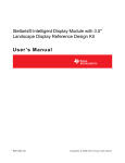
1
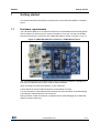
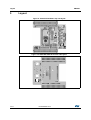
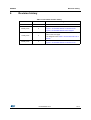
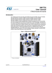
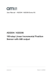
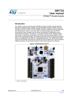
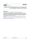
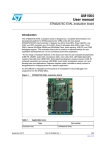
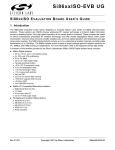
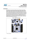
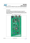
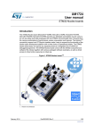
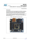
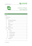
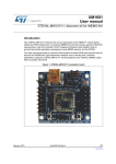
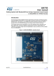
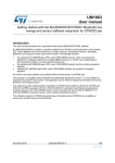
UM1820
User manual
Getting started with motion MEMS and environmental sensor
expansion board for STM32 Nucleo
Introduction
The X-NUCLEO-IKS01A1 is a MEMS inertial and environmental sensor evaluation board
which can be used to expand the STM32 Nucleo system. It is also compatible with the
Arduino UNO R3 connector layout and is designed around the STMicroelectronics 3-axis
accelerometer plus 3-axis gyroscope (LSM6DS0), 3-axis magnetometer (LIS3MDL),
humidity (HTS221) and pressure (LPS25HB*) sensors. The X-NUCLEO-IKS01A1 interfaces
with the STM32 MCU via the I²C pin, and the user can change the default I²C port.
This document details the hardware requirements and board connections for the XNUCLEO-IKS01A1 MEMS and environmental sensor expansion board for STM32 Nucleo.
Figure 1. X-NUCLEO-IKS01A1 evaluation board
May 2015
DocID026959 Rev 4
1/14
www.st.com
14
Contents
UM1820
Contents
1
Getting started . . . . . . . . . . . . . . . . . . . . . . . . . . . . . . . . . . . . . . . . . . . . . . 3
1.1
Hardware requirements . . . . . . . . . . . . . . . . . . . . . . . . . . . . . . . . . . . . . . . 3
2
System requirements . . . . . . . . . . . . . . . . . . . . . . . . . . . . . . . . . . . . . . . . 4
3
Hardware description . . . . . . . . . . . . . . . . . . . . . . . . . . . . . . . . . . . . . . . . 5
4
3.1
Board block diagram . . . . . . . . . . . . . . . . . . . . . . . . . . . . . . . . . . . . . . . . . 5
3.2
Sensor I²C address selection . . . . . . . . . . . . . . . . . . . . . . . . . . . . . . . . . . . 6
3.3
Sensor current consumption measurement . . . . . . . . . . . . . . . . . . . . . . . . 6
3.4
Sensor disconnection . . . . . . . . . . . . . . . . . . . . . . . . . . . . . . . . . . . . . . . . . 6
3.5
DIP24 socket for adapter boards . . . . . . . . . . . . . . . . . . . . . . . . . . . . . . . . 7
3.6
Connectors . . . . . . . . . . . . . . . . . . . . . . . . . . . . . . . . . . . . . . . . . . . . . . . . . 7
Board schematic and bill of material . . . . . . . . . . . . . . . . . . . . . . . . . . . . 9
4.1
Bill of material . . . . . . . . . . . . . . . . . . . . . . . . . . . . . . . . . . . . . . . . . . . . . . . 9
4.2
Schematic . . . . . . . . . . . . . . . . . . . . . . . . . . . . . . . . . . . . . . . . . . . . . . . . . .11
5
Layout . . . . . . . . . . . . . . . . . . . . . . . . . . . . . . . . . . . . . . . . . . . . . . . . . . . . 12
6
Revision history . . . . . . . . . . . . . . . . . . . . . . . . . . . . . . . . . . . . . . . . . . . 13
2/14
DocID026959 Rev 4
UM1820
1
Getting started
Getting started
This section describes the hardware requirements for the X-NUCLEO-IKS01A1 evaluation
board.
1.1
Hardware requirements
The X-NUCLEO-IKS01A1 is an expansion board for use with STM32 Nucleo boards (please
refer to UM1724 on www.st.com for further information). To function correctly, the STM32
Nucleo board must be connected to the X-NUCLEO-IKS01A1 board, as shown in Figure 2.
Figure 2. X-NUCLEO-IKS01A1 mounted on a STM32 Nucleo board
The connection between the STM32 Nucleo and the X-NUCLEO-IKS01A1 is designed for
use with any STM32 Nucleo board or Arduino UNO R3 platform.
When mounting the X-NUCLEO-IKS01A1 on the mainboard:
ensure that all the pins are aligned with their corresponding connector
It is very important to handle both boards carefully during this operation to avoid damaging
or bending the male/female pins and connectors.
ESD prevention measures must also be implemented to avoid damaging any X-NUCLEOIKS01A1 board components.
DocID026959 Rev 4
3/14
14
System requirements
2
UM1820
System requirements
Using the Nucleo boards with the X-NUCLEO-IKS01A1 expansion board requires the
following software and hardware:
®
•
a Windows (XP, Vista, 7, 8) PC on which to install the software
•
4/14
a USB type A to Mini-B USB cable to connect the Nucleo to the PC for installation of
the board firmware package (order code: X-CUBE-IKS01A1). A utility running on the
user's PC will complete the demo. The user’s PC must have the following
characteristics:
–
At least 128 MB of RAM
–
40 MB of available hard disk space for the X-CUBE-IKS01A1 firmware package
and relative documentation, available on www.st.com
DocID026959 Rev 4
UM1820
3
Hardware description
Hardware description
The board allows the user to test the functions of the STMicroelectronics motion MEMS
accelerometer, gyroscope, magnetometer and environmental sensors for humidity,
temperature and pressure.
The devices used on the board are:
–
LSM6DS0: MEMS 3D accelerometer (±2/4/8g) + 3D gyroscope
(±245/500/2000dps)
–
LIS3MDL: MEMS 3D magnetometer (±4/8/12/16 gauss)
–
LPS25HB*: MEMS pressure sensor, 260-1260 hPa absolute digital output
barometer
–
HTS221: Capacitive digital relative humidity and temperature sensor
The X-NUCLEO-IKS01A1 also has a DIL24 socket to connect and test additional sensors
(i.e. UVI sensors, other MEMS sensor, etc…).
The sensors are connected on a single bus via I²C and each device has a separate power
supply to allow measurement of the power consumption of each single sensor.
3.1
Board block diagram
Figure 3 shows a block diagram of the X-NUCLEO-IKS01A1 board.
Figure 3. X-NUCLEO-IKS01A1 block diagram
DocID026959 Rev 4
5/14
14
Hardware description
3.2
UM1820
Sensor I²C address selection
Most of the sensors allow selection of the LSB of the I²C address by pulling the SD0 pin low
or high. The board has solder bridges to control the SD0 level.
Table 1. Solder bridges for SD0 level control
3.3
Sensor
SD0 High
SD0 Low
LIS3MDL (U1)
SB3 (default)
SB4
LSM6DS0 (U2)
SB7 (default)
SB8
LPS25HB* (U4)
SB13 (default)
SB14
DIL24 Adapter (J1)
SB15/SB17
SB16/SB18 (default)
Sensor current consumption measurement
To measure the individual current consumption of each sensor, connect the ammeter at the
appropriate jumper points. Use an ammeter with a low burden voltage and set it to a suitable
range as the sensor current consumption is typically very low.
Table 2. Jumpers for current consumption measurement
3.4
Sensor
Jumper
LIS3MDL (U1)
JP1
LSM6DS0 (U2)
JP2
HTS221 (U3)
JP3
LPS25HB* (U4)
JP4
DIL24 Adapter (J1)
JP5
Sensor disconnection
To disconnect a sensor, disconnect the I²C bus as well as the power supply. Table 3 will help
you identify the appropriate jumpers and solder bridges.
Table 3. Link between sensors, jumpers and I²C solder bridges
6/14
Sensor
Power
SDA
SCL
LIS3MDL (U1)
JP1
SB2
SB1
LSM6DS0 (U2)
JP2
SB6
SB5
HTS221 (U3)
JP3
SB9
SB10
LPS25HB* (U4)
JP4
SB12
SB11
DocID026959 Rev 4
UM1820
3.5
Hardware description
DIP24 socket for adapter boards
Sensors can be added via adapter boards connected to the DIL24 socket J1. Please visit
www.st.com to find other sensors that are available.
As there are various interrupt signal assignments to DIL24 pins, the appropriate pin can be
selected using the JP6 header.
3.6
Connectors
The pin assignments for the Arduino UNO R3 and the Morpho connectors are shown in
Table 4 and Table 5 respectively.
Table 4. Arduino UNO R3 connector table
Connector
Pin(1)
Signal
7
GND
9
I²C SDA
10
I²C SCL
2
3.3V
4
3.3V
6
GND
7
GND
3
INT1 (DIL24)
4
INT2 (DIL24)
5
LIS3MDL INT1
6
LIS3MDL DRDY
3
USER INT (optional)
5
LSM6DS0 INT1
6
LPS25HB* INT1
7
HTS221 DRDY
CN5
CN6
Remarks
-
-
CN8
-
CN9
-
1. Any unlisted pins are not connected.
DocID026959 Rev 4
7/14
14
Hardware description
UM1820
Table 5. ST Morpho connector table
Connector
Pin(1)
Signal
12
3.3V
16
3.3V
20
GND
22
GND
32
INT1 (DIL24)
34
INT2 (DIL24)
36
LIS3MDL INT1
38
LIS3MDL DRDY
3
I²C SCL
5
I²C SDA
25
HTS221 DRDY
27
LPS25HB* INT1
29
LSM6DS0 INT1
33
USER INT (optional)
Remarks
CN7
CN10
1. Any unlisted pins are not connected.
8/14
DocID026959 Rev 4
UM1820
4
Board schematic and bill of material
Board schematic and bill of material
This section contains the bill of material, schematic and layout of the X-NUCLEO-IKS01A1.
4.1
Bill of material
Table 6. X-NUCLEO-IKS01 bill of material
Designator
Value
Part number
5
C1, C2, C4, C7,
C8
100nF
CAP CER 0603
100nF 25V X7R
10%
0603
2
C3, C5
10uF
CAP CER 0805
10uF 10V X7R
10%
0805
1
C6
10nF
CAP CER 0603
10nF 25V X7R
10%
0603
1
C9
4.7uF
CAP CER 0805
4.7uF 16V X7R
10%
0805
1
CN5
Header 10x1
Extra-long 10 pins
Female side
female-male strip mounted to the top
HDR1X10
2
CN6, CN9
Header 8x1
Extra-long 8 pins
female-male strip
Female side
mounted to the top
HDR1X8
2
CN7, CN10
Header 19x2
Header, 19-Pin,
Dual row
Not mounted
HDR2X19
1
CN8
Header 6x1
Extra-long 6 pins
female-male strip
Female side
mounted to the top
HDR1X6
1
J1
DIL24 Socket
DIL24 Socket
DIL24
5
JP1, JP2, JP3,
JP4, JP5
Header 2x1
Header 1x2 pins,
2.54mm, straight
HDR1x2
1
JP6
Header 4x2
Header 2x4 pins,
2.54mm, straight
HDR2x4
2
R1, R2
4k7
RES 0603 4k7 1%
1/16W
0603
1
R3
2k2
RES 0603 2k2 1%
1/16W
0603
DocID026959 Rev 4
Comment
Package
reference
Quantity
9/14
14
Board schematic and bill of material
UM1820
Table 6. X-NUCLEO-IKS01 bill of material (continued)
Quantity
Designator
Value
Part number
Comment
Package
reference
23
SB1, SB2, SB3,
SB5, SB6, SB7,
SB9, SB10,
SB11, SB12,
SB13, SB16,
SB18, SB19,
SB20, SB21,
SB22, SB23,
SB24, SB25,
SB26, SB27,
SB28
Solder Bridge
R0603 0R
Close
0603
5
SB4, SB8,
SB14, SB15,
SB17
Solder Bridge
Open
0603
3
TP1, TP2, TP3
Header 1x1
Header 1x1 pins,
2.54mm, straight
Not mounted
1
U1
LIS3MDL
LIS3MDL
ST-SUPPLY
LGA 2x2 12L
1
U2
LSM6DS0
LSM6DS0
ST-SUPPLY
LGA 3x3 16L
1
U3
HTS221
HTS221
ST-SUPPLY
HLGA 2x2 6L
1
U4
LPS25HB*
LPS25HB*
ST-SUPPLY
HCLGA 2.5x2.5
10L
10/14
DocID026959 Rev 4
&6
*1'
DocID026959 Rev 4
6&/
9GG
/,60'/B,17
/,60'/B'5'<
6%
6%
$UGXLQR&RQQHFWRU $UGXLQR&RQQHFWRU
0B,17
0B,17
86(5B,17
/60'6B,17
/36+B,17
+76B'5'<
$UGXLQR&RQQHFWRU
6%
6%
$UGXLQR&RQQHFWRU
&1
6%
6%
6%
6%
&1
*1'
6%
6%
,&B6'$
,&B6&/
+HDGHU[
&1
&1
&1
$UGXLQR0RUSKR&RQQHFWRUV
6&/
*1'
5HV
9GGB,2
6'$
9GG
+HDGHU[
9
6'2
*1'
6'$
,&B6&/
6%
Q)
X)
8
*1'
&1
,&B6&/
&
&
/36+%
5(6
5(6
5(6
*1'
*1'
&6
,17
/60'6B,17
3UHVVXUHVHVQVRU
6%
9
+76B'5'<
,&B6'$
-3
'5'<
6%
8
+76
*1'*1'
X)
&
&6
6'26$
6'$6',6'2
6&/63&
9GGB,2
5HODWLYHKXPLGLW\DQGWHPSHUDWXUHVHQVRU
*1'
&
Q)
&
X)
*1' *1'
Q)
9
Q)
6%
6%
5(6
-3
9GG
*1'
&
9GGB,2
6%
2SHQ
6%
,&B6'$
,&B6&/
,17
&
/,60'/B,17
*1'
/,60'/B'5'<
6%
2SHQ
5(6
Q)
&
,17
'5'<
6'2
/60'6
&DS
5(6
9
5HV
-3
&
6'$
*1'
*1'
5HV
&6
9
6&/
6%
,&B6'$
8
*1'
Q)
&
,&B6'$
2SHQ
6%
6%
/36+B,17
*1'
6%
'DFFHOHURPHWHUDQG'J\URVFRSH
9GG
6%
-3
6%
/,60'/
0DJQHWLFVHVQVRU
,&B6&/
8
9
-3
5
N
9
73
86(5B,17
-
5
N
5
N
73
*1'
73
0B,17B3LQ
0B,17B3LQ
0B6$'5'<
0B,17B3LQ
0B,17B3LQ
0B6$'(1
0B6$'5'<
,&B6'$
,&B6&/
0B&6B3LQ
0B&6B3LQ
0B,17B3LQ
0B,17B3LQ
0B,17
0B,17
9
-3
',/6RFNHWIRU$GDSWHU%RDUG
6%
2SHQ
6%
6%
2SHQ
6%
4.2
0RUSKRFRQQHFWRU
UM1820
Board schematic and bill of material
Schematic
Figure 4. X-NUCLEO-IKS01A1 circuit schematic
,&B6&/
,&B6'$
0RUSKRFRQQHFWRU
*63*6*
11/14
14
Layout
5
UM1820
Layout
Figure 5. X-NUCLEO-IKS01A1 top side layout
Figure 6. X-NUCLEO-IKS01A1 bottom side layout
12/14
DocID026959 Rev 4
UM1820
6
Revision history
Revision history
Table 7. Document revision history
Date
Revision
Changes
06-Nov-2014
1
Initial release.
08-May-2015
2
Updated:
- Figure 1: X-NUCLEO-IKS01A1 evaluation board
- Figure 3: X-NUCLEO-IKS01A1 block diagram
14-May-2015
3
Updated:
- Title on the cover page
- U2 designator value Table 6: X-NUCLEO-IKS01 bill of
material
29-May-2015
4
Updated:
- Figure 1: X-NUCLEO-IKS01A1 evaluation board
DocID026959 Rev 4
13/14
14
UM1820
IMPORTANT NOTICE – PLEASE READ CAREFULLY
STMicroelectronics NV and its subsidiaries (“ST”) reserve the right to make changes, corrections, enhancements, modifications, and
improvements to ST products and/or to this document at any time without notice. Purchasers should obtain the latest relevant information on
ST products before placing orders. ST products are sold pursuant to ST’s terms and conditions of sale in place at the time of order
acknowledgement.
Purchasers are solely responsible for the choice, selection, and use of ST products and ST assumes no liability for application assistance or
the design of Purchasers’ products.
No license, express or implied, to any intellectual property right is granted by ST herein.
Resale of ST products with provisions different from the information set forth herein shall void any warranty granted by ST for such product.
ST and the ST logo are trademarks of ST. All other product or service names are the property of their respective owners.
Information in this document supersedes and replaces information previously supplied in any prior versions of this document.
© 2015 STMicroelectronics – All rights reserved
14/14
DocID026959 Rev 4