1
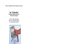
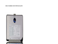
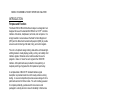
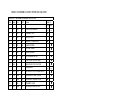
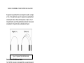
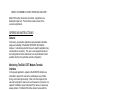
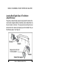
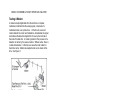
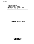
ESL Model 700 EIA RS-232 Interface Analyzer Cat No. 301030 The “Tri-State Box” User’s Manual 36 Western Industrial Drive Cranston, RI 02921 Tel: 401-943-1164 www.electrostandards.com Pub. 2903-03 MODEL 700 MODEM & POCKET INTERFACE ANALYZER Use and Installation Manual Model 700 EIA RS-232 INTERFACE ANALYZER • Dynamic! Tri-State Led’s Display Red, Green, & Off To Indicate Signal Status • Completely portable: Lightweight, Pocket-Sized, Battery Powered Rugged Aluminum Case And Metal Hinge That Will Not Break! Tests Synchronous Or Asynchronous Modems, Terminals, Multiplexers 24 Mini-Switches, 4 Mini Patchcords Comprehensive User Manual Displays All Modem & Terminal Interface Signals Compatible With EIA RS-232, CCITT V.24, And MIL-188C Separate EIA Cable Facilitates Use At Either Modem OR Terminal End Test Points To Access All 25 Pins Of Both DCE And DTE Connector Can Also Be Utilized To Determine Custom Cable Designs • • • • • • • • • The “Tri-State Box”® REPRODUCTION AND DISTRIBUTION OF THIS TECHNICAL MANUAL IS AUTHORIZED FOR GOVERNMENT PURPOSES. Electro Standards laboratories, Inc. www.electrostandards.com - pg 1 - (401) 943-1164 Pub. 2902-03 MODEL 700 MODEM & POCKET INTERFACE ANALYZER Electro Standards laboratories, Inc. www.electrostandards.com - pg 2 - (401) 943-1164 Pub. 2902-03 MODEL 700 MODEM & POCKET INTERFACE ANALYZER SAFETY ....................................................................................................7 INTRODUCTION ....................................................................................9 PURPOSE AND FUNCTION..........................................................................9 PERFORMANCE CHARACTERISTICS AND CAPABILITIES ..............................9 UNPACKING ...........................................................................................10 ITEMS FURNISHED ..................................................................................11 INSTALLATION .......................................................................................11 PRINCIPLES OF OPERATION ..........................................................11 CONTROLS AND INDICATORS ..................................................................11 Tri-State Indicators...........................................................................11 Switches ............................................................................................13 Test Points & Mini-Patchcords ........................................................13 Connectors & EIA Ribbon Cable......................................................14 OPERATING INSTRUCTIONS...........................................................15 GENERAL ...............................................................................................15 MONITORING THE EIA-CCITT MODEM-TERMINAL INTERFACE .............15 Test Procedure..................................................................................15 Test Procedure..................................................................................16 Test Results.......................................................................................16 LOOPING BACK DIGITAL DATA AT THE MODEM (ASYNCHRONOUS).......17 Test Procedure.............................................................................17 Test Results.......................................................................................18 LOOPING BACK DIGITAL DATA AT THE TERMINAL (ASYNCHRONOUS)...18 Test Procedure..................................................................................18 TESTING A MODEM................................................................................19 Test Procedure..................................................................................19 Test Results.......................................................................................20 MONITORING THE EIA-CCITT INTERFACE AT TECH CONTROL CENTER.20 Test Procedure..................................................................................20 Test Results.......................................................................................20 SPECIFICATIONS ................................................................................20 SHIPPING AND STORAGE.................................................................22 MAINTENANCE ...................................................................................22 WARRANTY ..........................................................................................23 Electro Standards laboratories, Inc. www.electrostandards.com - pg 3 - (401) 943-1164 Pub. 2902-03 MODEL 700 MODEM & POCKET INTERFACE ANALYZER The “Tri-State Box” ESL Model 700 Modem & Terminal Interface Pocket Analyzer Dynamic Tri-State LED’s Display Red, Green, and a Mixture (Orange) For Accurate Datacomm Testing. The unique Model 700 EIA RS-232 Interface Analyzer utilizes tri-state LED’s to clearly display polarity, activity, and validity of all key interface signals simultaneously. Compact and battery powered, ideal for computer room use or field service use. Electro Standards laboratories, Inc. www.electrostandards.com - pg 4 - (401) 943-1164 Pub. 2902-03 MODEL 700 MODEM & POCKET INTERFACE ANALYZER Model 700 Front Panel Electro Standards laboratories, Inc. www.electrostandards.com - pg 5 - (401) 943-1164 Pub. 2902-03 MODEL 700 MODEM & POCKET INTERFACE ANALYZER Electro Standards laboratories, Inc. www.electrostandards.com - pg 6 - (401) 943-1164 Pub. 2902-03 MODEL 700 MODEM & POCKET INTERFACE ANALYZER SAFETY • Be sure to clear case of all obstructions when closing. Do not attempt to store an excessive amount of items in the storage compartment. • When installing batteries, pay close attention to insert batteries according to the battery polarity diagram located on the inside of the battery compartment. • When using jumper wires from test points, be careful not to short signals to the chassis. Also take care not to connect ground, positive voltage, and negative voltage together. Electro Standards laboratories, Inc. www.electrostandards.com - pg 7 - (401) 943-1164 Pub. 2902-03 MODEL 700 MODEM & POCKET INTERFACE ANALYZER Electro Standards laboratories, Inc. www.electrostandards.com - pg 8 - (401) 943-1164 Pub. 2902-03 MODEL 700 MODEM & POCKET INTERFACE ANALYZER INTRODUCTION Purpose and Function The Model 700 EIA RS-232 Interface Analyzer is a diagnostic tool designed for use at the standard EIA RS-232 or CCITT V.24 data interface of modems, multiplexers, terminals, and computers. It is simply inserted in series between the Data Terminal Equipment (DTE) and the Data Communications Equipment (DCE) to provide access to and monitoring of all data, timing, and control signals. The unit is of optimum design utilizing state-of-the-art tri-state lightemitting diodes to clearly display polarity, activity, and validity of all interface signals. Miniature rocker switches allow the user to program a ‘make’ or ‘break’ for each signal at the DCE/DTE interface. Mini-patchcords are provided for cross-patching or loopback patching of signals at the front panel test point array. A complete table of EIA/CCITT standard interface signal description is provided inside the unit for ready reference during testing. A covered compartment provides secure storage for minipatchcords and an EIA ribbon cable. The unit is battery-powered for complete portability, pocket-sized for convenience and packaged in a sturdy aluminum case for durability in field service use. The Model 700’s high utility and versatility at an economical price make it a ‘must’ for every data communications user. Performance Characteristics and Capabilities Large Tri-State (Red/Green/Off) LED Display • • • • • • • • A MARK signal is displayed in RED A SPACE signal is displayed in GREEN Clock activity is displayed as mixed RED & GREEN (ORANGE) DATA activity is displayed as mixed RED & GREEN (ORANGE) Illegal level or open-circuit is displayed as OFF Location of LED’s on panel indicate signal source Fourteen tri-state LED’s, including a spare Exclusive SCTE monitor for external timed modems Full Access To All Interface Signals Via Test Points • Test Points for all 25 DCE and 25 DTE connector pins Electro Standards laboratories, Inc. www.electrostandards.com - pg 9 - (401) 943-1164 Pub. 2902-03 MODEL 700 MODEM & POCKET INTERFACE ANALYZER • • Provide means of cross-patching or loopback of signals Ample supply of mini-patchcords Twenty-four Miniature Switches • • Provide capability to program each signal for make or break Switches facilitate break-and-patch operation Easily Inserted In At Data Interface Between DCE and DTE • • • Reliable panel-mounted connectors to both DCE and DTE Separate EIA ribbon cable allows application at either DCE or DTE end of data cable Data cable and mini-patchcord storage compartment provided Complete EIA-CCITT Modem-Terminal Interface Chart • Located on inside panel for easy reference Interfaces With All Modems and Terminals • • • • Indicators buffered to prevent loading interface signals Full-duplex and half-duplex monitoring Synchronous or asynchronous applications Compatible with EIA RS-232, CCITT V.24, MIL-188C For Field Service Or Data Center Use • • • Rugged aluminum case with sturdy metal hinge and latch! Completely portable and battery-powered Lightweight and pocket-sized Economical, Low-Priced, High Capability Unpacking Each unit is thoroughly inspected and tested before shipment. Upon receipt, the user should inspect it for shipping damage. If any shipping damage is suspected, refer to the Maintenance section of this manual. The serial number of the unit is on the battery tag located in the storage compartment. Refer to this serial number in all correspondence with the factory or distributor/sales representative. Electro Standards laboratories, Inc. www.electrostandards.com - pg 10 - (401) 943-1164 Pub. 2902-03 MODEL 700 MODEM & POCKET INTERFACE ANALYZER Items Furnished • • • • • • • (4) size AA batteries ten-inch long EIA Male/Female ribbon cable (1) 3-to-1 mini-patchcord (3) 1-to-1 mini-patchcords (1) flat head screwdriver Use and Installation manual provided both as a hard copy and on CD Maintenance and Service manual provided both as a hard copy and on CD Installation Before the unit can be operated, power must be supplied either by (4) AA batteries or by a DC power source. When installing batteries, be sure the polarity of the batteries is correct per the label inside the unit. Once powered, the unit is ready for operation. PRINCIPLES OF OPERATION Controls and Indicators Tri-State Indicators The Model 700 utilizes state-of-the-art tri-state light-emitting diodes to indicate the status of key signals at the EIA/CCITT data interface. The use of tri-state indicators represents an advancement in interface monitoring technology. They present the user with a maximum of signal status information. Interpretation of the display is as follows. For data signals (Transmit Data and Receive Data), a red indication signifies a Mark condition, a green indication signifies a Space condition, an off indication signifies an improper signal (between +3 volts and -3 volts) or an open circuit. A mixture of red and green signifies data transitions. For clock signals (Transmit Clock, Receive Clock, and Serial Clock Transmit External), a mixed red and green indication signifies the presence of an active clock, a red indication signifies that the clock line is more negative than -3 volts, a green indication signifies that the clock line is more positive than + 3 volts, an off indication signifies an improper signal (between +3 volts and - 3 volts) or an open circuit. A summary of the tri-state LED display indications is presented in Table 1. Electro Standards laboratories, Inc. www.electrostandards.com - pg 11 - (401) 943-1164 Pub. 2902-03 MODEL 700 MODEM & POCKET INTERFACE ANALYZER EIA-CCITT MODEM-TERMINAL INTERFACE PIN NAME EIA CCITT SIGNAL 1 PG AA 101 PROTECTIVE GROUND 2 TD BA 103 TRANSMIT DATA 3 RD BB 104 RECEIVE DATA 4 RTS CA 105 REQUEST TO SEND DATA 5 CTS CB 106 CLEAR TO SEND 6 DSR CC 107 DATA SET READY 7 SG AB 102 SIGNAL GROUND 8 DCD CF 109 DATA CARRIER DETECT SOURCE DTE DCE — — — 9 POS — — POSITIVE DC TEST VOLTAGE 10 NEG — — NEGATIVE DC TEST VOLTAGE 11 — — — UNASSIGNED 12 SDCD SCF 122 SECONDARY DATA CARRIER DETECT 13 SCTS SCB 121 SECONDARY CLEAR TO SEND 14 STD SBA 118 SECONDARY TRANSMIT DATA 15 TC DB 114 TRANSMIT CLOCK 16 SRD SBB 119 SECONDARY RECEIVE DATA 17 RC DD 115 RECEIVE CLOCK 18 — — — UNASSIGNED 19 SRTS SCA 120 SECONDARY REQUEST TO SEND 20 DTR CD 108.2 DATA TERMINAL READY 21 SQ CG 110 SIGNAL QUALITY DETECT 22 RI CE 125 RING INDICATOR 23 — CH/CI 111/112 DATA RATE SELECTOR 24 SCTE DA 113 SERIAL CLOCK TRANSMIT, EXTERNAL 25 BUSY — — BUSY — — / Table 1. Tri-State LED Display and Data Interface Electro Standards laboratories, Inc. www.electrostandards.com - pg 12 - — — (401) 943-1164 Pub. 2902-03 — / MODEL 700 MODEM & POCKET INTERFACE ANALYZER Switches The Model 700 utilizes 24 miniature rocker switches to allow any of the interface signals (except frame ground) to be interrupted. A rocker switch in the ON position is programmed to pass the signal between the DCE and DTE connectors. A rocker switch in the OFF position is programmed to interrupt the signal between the DCE and DTE connectors. Switches are identified by the test points adjacent to them. They are numbered in order from top to bottom (pins 2 through 25). Test Points & Mini-Patchcords There are twenty-five test points on the right half of the front panel. They are connected directly to the 25 pins on the ‘TO DCE’ connector and are labeled 1 through 25. There are 24 additional test points on the left half of the front panel. They are connected directly to their respective pins on the ‘TO DTE’ connector and are labeled 2 through 25. Since pin 1 is chassis ground which is bussed through, the test point labeled 1 is actually connected to pins 1 on both the ‘TO DCE’ and ‘TO DTE’ connectors. There is a spare test point / LED circuit to allow any signal pin, with or without a dedicated LED, to be monitored for signal activity. There is a set of two voltage test points, (+) positive and (-) negative, that provide the ability to apply test signals onto the other signal test pins of the interface. The test points usage is multi-fold. They serve as access points for signals that are being passed between DCE and DTE. But when the respective rocker switch is programmed to interrupt the signal, the test points serve as a signal pickup point or a signal injection point. In order to accomplish this, mini-patchcords are supplied. A signal may be ‘picked up’ at one test point that is connected to the signal source and ‘injected’ at another test point that is to be the signal’s new destination. This process is called cross-patching, or simply ‘patching’. Application examples appear in following sections of this manual. Electro Standards laboratories, Inc. www.electrostandards.com - pg 13 - (401) 943-1164 Pub. 2902-03 MODEL 700 MODEM & POCKET INTERFACE ANALYZER If a signal is to be patched from one test point to another, a ‘single’ or ‘1-to-1’ mini patchcord is used. If a signal is to be patched from one test point to two or three other test points, a ‘triple’ or ‘3-to-1’ mini-patchcord is used. Mini-patchcords are stored in the covered compartment. Mini-patchcords are illustrated in Figure 1. Figure 1. Single and Triple Mini-Patchcords Connectors & EIA Ribbon Cable The ‘TO DTE’ connector on the Model 700 is a socket (female) 25pin EIA RS-232, socket. The ‘TO DCE’ connector is a plug (male), 25-pin EIA RS-232, plug. A pin/signal list for the EIA RS-232 and CCITT V.24 data interface is given in Table 1. “Socket” view and “Plug” view of the 25-pin EIA RS-232 connectors are illustrated in Figure 2. Figure 2. Socket and Plug Views of EIA RS-232 Connectors A 10-inch EIA ribbon cable is supplied to facilitate connecting the Electro Standards laboratories, Inc. www.electrostandards.com - pg 14 - (401) 943-1164 Pub. 2902-03 MODEL 700 MODEM & POCKET INTERFACE ANALYZER Model 700 to either the modem or terminal. Applications are illustrated in later text. The EIA ribbon cable is stored in the covered compartment. OPERATING INSTRUCTIONS General A few basic, yet powerful, applications are presented to illustrate usage and versatility of the Model 700 EIA RS-232 Interface Analyzer. Customizing a test for the user’s specific application may occasionally be necessary. The user is encouraged to document test configurations that he determines to be most effective in faultisolation activity for his particular network configuration. Monitoring The EIA-CCITT Modem-Terminal Interface In this popular application, signals at the DCE-DTE interface are monitored to present the user with a simultaneous view of data, timing, and control signal activity. Often, with this single test, the user will recognize the absence or out-of-sequence occurrence of a required ‘handshake’ signal and pinpoint the cause of a previously elusive problem. The Model 700 will be placed in series with the data cable connecting the Modem and Terminal per the following procedure. See Figure 3. Figure 3. Model 700 in Series with Terminal & Modem Electro Standards laboratories, Inc. www.electrostandards.com - pg 15 - (401) 943-1164 Pub. 2902-03 MODEL 700 MODEM & POCKET INTERFACE ANALYZER Test Procedure (1) Program all switches to the ON position. (2) Remove any jumpers that may be in test points from previous tests. (3) The Model 700 may be inserted in series at either end of the data cable connecting the DCE and DTE. If at the DCE end: Disconnect the data cable from the DCE device and plug into the Model 700 connector labeled ‘TO DTE’. Then plug the Model 700 ribbon cable into its connector labeled ‘To DCE’ and plug the other end of the ribbon cable into the DCE device. If at the DTE end: Disconnect the data cable from the DTE device and plug it into the Model 700 connector labeled ‘TO DCE’. Then plug the Model 700 ribbon cable into its connector labeled ‘TO DTE’ and plug the other end into the DTE device. Test Results (1) TD and RD indicators should be in a mixed red and green state, signifying Transmit Data and Receive Data activity. (2) DTR and DSR indicators should be in the green state, signifying both terminal and modem are ready for the data activity. (3) RTS and CTS indicators should be green when the DTE is transmitting data, signifying that the terminal has requested carrier for its transmission and sufficient time has passed for the link to have settled on the carrier to accept data. (4) DCD indicator should be green when receiving data signifying the detection of a carrier by the local modem. (5) TC and RC indicators should be mixed red and green for synchronous modems, indicating the presence of the Transmit Clock and Receive Clock, respectively. An exception to this occurs when the modems are of the externally timed type. (6) For synchronous, externally timed modems, the RC and SCTE indicators should be mixed red and green, indicating the presence of Receive Clock and Serial Clock Transmit External, respectively. (7) The SPARE indicator may be patched via its test point input to any test point at the EIA interface that may not have a dedicated LED. Electro Standards laboratories, Inc. www.electrostandards.com - pg 16 - (401) 943-1164 Pub. 2902-03 MODEL 700 MODEM & POCKET INTERFACE ANALYZER Looping Back Digital Data At The Modem (Asynchronous) Frequently, network testing requires looping back the data at the local modem’s digital interface to facilitate a test initiated from the far end modem or terminal. This requires disconnecting the local terminal from the modem and replacing it with the Model 700, per the following steps. See Figure 4. Figure 4. Digital Loopback Test Test Procedure (1) Disconnect the EIA data cable at the modem end and set it aside. (2) Plug one end of the Model 700’s EIA ribbon cable into the front panel ‘TO DCE’ connector and the other end of the ribbon cable into the modem’s data connector. (3) Place a mini-patchcord between DCE test points 2 and 3. This loops RD back as TD. (4) Place a mini-patchcord between DCE test points 6 and 20. This uses DSR to satisfy the modem’s requirement for a DTR signal. (5) Program all switches ON. This allows monitor circuits on the DTE side of the Model 700 to indicate status of signals normally supplied by the terminal but synthesized from modem signals via the mini-patchcord strapping arrangement. Electro Standards laboratories, Inc. www.electrostandards.com - pg 17 - (401) 943-1164 Pub. 2902-03 MODEL 700 MODEM & POCKET INTERFACE ANALYZER Test Results (1) TD and RD indicators are mixed red/green signifying receive data activity is being looped back as transmit data. (2) DSR and DTR indicators are green, signifying DSR is being used to supply DTR signal. (3) DCD indicator is green, signifying that a proper carrier is being detected by the local modem. (4) At the far end modem, data being transmitted to the local modem is being received as RD. Looping Back Digital Data At The Terminal (Asynchronous) Data from a terminal or computer may be looped back to facilitate testing that device. Test Procedure (1) Disconnect the EIA data cable at the terminal end and set it aside. (2) Plug one end of the Model 700’s EIA ribbon cable into the front panel ‘TO DTE’ connector and the other end of the ribbon cable into the terminal or computer’s data connector. (3) Place a mini-patchcord between DTE test points 2 and 3, looping data. (4) Place a mini-patchcord between DTE test points 4 and 5. This uses RTS to satisfy the terminals requirement for a CTS signal. (5) Place a mini-patchcord between DTE test points 6 and 20. This uses DTR to satisfy DSR signal requirement. (6) Program all switches ON. Monitor circuits will indicate status of all interface signals (7) Test Results (8) TD and RD indicators are mixed red/green signifying transmit data activity is being looped back as receive data. (9) RTS and CTS indicators are green, signifying RTS is being used to supply the CTS signal. (10) DSR and DTR indicators are green, signifying DTR is being used to supply the DSR signal. Electro Standards laboratories, Inc. www.electrostandards.com - pg 18 - (401) 943-1164 Pub. 2902-03 MODEL 700 MODEM & POCKET INTERFACE ANALYZER Testing A Modem A modem accepts digital data from the terminal or computer, modulates it and transmits the analog signal, comprised of a modulated carrier, over phone lines. At the far end, a second modem detects the carrier and modulation, demodulates the signal and restores the data to its digital form for use by the terminal at that end of the data link. A crucial ingredient in this process is the detection of carrier by the receive modem. Without carrier, there is no data transmission. In this test, we cause the local modem to transmit a carrier. Modem level adjustments can be made at this time. See Figure 5. Figure 5. Testing a Modem Test Procedure (1) Disconnect data cable from modem. (2) Plug Model 700 ribbon cable into its ‘TO DCE’ connector and the other end into the modem. (3) Use the triple mini-patchcord to tie test points 6 (DSR). 4 (RTS), and 20 (DTR) together. (4) Place a mini-patchcord between DTE test points 2 (TD) and 5 (CTS). This places a Space signal on the Transmit Data line. (5) Program all switches to ON. Monitor circuits will indicate status of all interface signals. Electro Standards laboratories, Inc. www.electrostandards.com - pg 19 - (401) 943-1164 Pub. 2902-03 MODEL 700 MODEM & POCKET INTERFACE ANALYZER Test Results (1) RTS and CTS indicators are green. (2) The modem is transmitting carrier. (3) The modem will transmit a Mark when switch #2 is programmed OFF (open circuit) and will transmit a Space when switch #2 is programmed ON. Monitoring the EIA-CCITT Interface At Tech Control Center Tech control center switch, patch, and monitor modules often have a monitor port on their front panel. That access point may be patched directly into either connector of the Model 700 to allow monitoring the status of all interface signals. Test Procedure (1) Use patch panel monitor connector to EIA connector adapter cable and patch directly from tech control module to Model 700. (2) Program all Model 700 switches to On. Test Results (1) All interface signals will be monitored and signal status displayed on the tri-state LED’s. SPECIFICATIONS Input Signal: + 25 volts per EIA RS-232 More positive than +2.5 volt for green indication More negative than -2.5 volt for red indication Input Impedance: Greater than 30 K ohms Environment: Operation Temperature: 00C to 500C Storage Temperature: -400C to 900C Humidity: 10% to 90% without condensation Electro Standards laboratories, Inc. www.electrostandards.com - pg 20 - (401) 943-1164 Pub. 2902-03 MODEL 700 MODEM & POCKET INTERFACE ANALYZER Size: Length: 4.0 in (10.16 cm) Width: 5.25 in (13.33 cm) Height: 1.75 in (4.45 cm) Weight: 15 ounces (426 grams) Power: Four 1.5 volt, size AA batteries Test Points: A total of 50 test points providing access to all 25 pins on the DCE connector, all 25 pins on the DTE connector, and one for access to the spare LED. A pair of signal voltage test points, (+) positive and (-) negative, allowing test signal to be applied to interface test points.Switches: 24 miniature rocker switches provide individual ON/OFF control of signals passing through between the DCE and DTE connectors. Display: Fourteen Tri-state LED (Red/Green/Off) Indicators Pin 2 3 4 5 6 8 15 17 20 21 22 24 25 - Signal (TD) (RD) (RTS) (CTS) (DSR) (DCD) (TC) (RC) (DTR) (SQ) (RI) (SCTE) (Busy) (SPARE) Transmit Data Receive Data Request to Send Clear to Send Data Set Ready Data Carrier Detect Transmit Clock Receive Clock Data Terminal Ready Signal Quality Ring Indicator Serial Clock Transmit, Ext. Busy Uncommitted Electro Standards laboratories, Inc. www.electrostandards.com - pg 21 - (401) 943-1164 Pub. 2902-03 MODEL 700 MODEM & POCKET INTERFACE ANALYZER I/O Connectors: TO DCE - A 25-pin EIA RS-232 connector provides connector to Data Communications Equipment. (socket) TO DTE - A 25-pin EIA RS-232 connector provides connector to Data Terminal Equipment. (plug) Cables & Patchcords: EIA: A ten-inch long male/female EIA ribbon cable for connection to DCE or DTE. Patchcords: Three single (1-to-1) patchcords and one triple (3-to-1) patchcord for use with test points. EIA-CCITT Modem Terminal Interface Label: A convenient chart for reference during testing. Describes relationship between EIA, CCITT, Signal Nomenclature, Signal Source. Packaging: Durable aluminum case with metal hinge and clasp. Storage compartment for EIA cable and patchcords. Scuff-proof coated. Attractively styled. SHIPPING AND STORAGE When shipping or storing the unit, be sure to remove batteries. MAINTENANCE The Model 700 is a solid state device utilizing reliable computer circuitry. It requires no tuning or adjustments. There is no calibration needed. Routine maintenance is the replacement of batteries, as may be required. Repairs should be made at the factory. For maximum efficiency and quick repair turnaround, call the factory for a return authorization number and shipping instructions. You will be requested to supply your name, phone number, purchase order number and a return ship to address for the repaired unit. Electro Standards laboratories, Inc. www.electrostandards.com - pg 22 - (401) 943-1164 Pub. 2902-03 MODEL 700 MODEM & POCKET INTERFACE ANALYZER For self repair, see the Maintenance and Service Manual. WARRANTY The Model 700 is guaranteed against defects in material and workmanship for a period of one year after receipt by original purchaser. Under this warranty, defective equipment will either be repaired or replaced at the option of ESL. Units returned to factory for repair must be shipped prepaid. Shipping and handling charges for the return of repaired equipment shall be prepaid by ESL and billed to the customer. Replacement of batteries is not covered by this warranty. Authorization for return of equipment for repair must be obtained prior to sending equipment to the factory. Liability under this Warranty is limited to the replacement value of the Model 700. The Warranty is voided if the unit is not operated in accordance with the instruction manual or ESL application notes. Unauthorized modification or repairs of the unit may void the warranty, at the discretion of ESL. © September 14, 2010 Electro Standards Laboratories. All rights reserved. 36 Western Industrial Drive Cranston, RI 02921 Tel: 401-943-1164 Fax: 401-946-5790 E-mail: [email protected] Electro Standards laboratories, Inc. www.electrostandards.com - pg 23 - (401) 943-1164 Pub. 2902-03 MODEL 700 MODEM & POCKET INTERFACE ANALYZER Electro Standards laboratories, Inc. www.electrostandards.com - pg 24 - (401) 943-1164 Pub. 2902-03 36 Western Industrial Drive Cranston, RI 02921 Tel: 401-943-1164 www.electrostandards.com Pub. 2903-03