Download I/O PLUS II
Transcript
I/O PLUS II
Table of Contents
IBM
PCTM ,
PC/XTTM ,
PC/ATTM
International Business
are registered trademarks of
Page
Machines Corp .
A .0
Introducing the I/O Plus II 1
l .l
*Do I really Need to Read This Manual?"2
A .2
System Requirements - Non-PC DOSTM Operation2
2.0
Getting Started
2 .A
Removing the PC TM System Unit Cover3
3 .0
Serial Asynchronous Communication Using Serial
3
Port # 1 (and Option S, Serial Port # 2)4
3 .1
Setting Up Serial Port # 1
3 .2
If Your System Already Has a Serial Port 5
3 .3
RS-232 Connector Pin List for Serial Port # 1 6
3 .4
Disabling Serial Port # 1
8
3 .5
Option S : Serial Port # 2 8
3 .6
Verifying Your Serial # 2 Configuration 8
3 .7
DTE and DCE Interface Selection for Serial # 2 9
3 .8
Setting Up Serial # 2 for DCE Configuration 9
3 .9
DCE Configuration : Serial # 2 RS-232 Pin
Connector Listing
5
10
3 .10 Installing the Serial # 2 Interface Cable 10
3 .11 Configuring Your Application Software 11
3 .12 Disabling Serial Port # 2
12
4 .0
Parallel Printer Port (Option P) 13
4 .A
Installing the Interface Cable
13
4 .2
Reconfiguring Your Parallel Port for
Multi-Port Systems
14
4 .3
Reconfiguring Your Parallel Printer Software 15
4 .4
Printer Port Connections
15
4 .5
Disabling the Parallel Printer Port 15
5 .0
Clock-Calendar Feature
17
5 .A
Initialization
17
S .2
Setting the TIME and DATE 18
5 3
Device Addressing of the Clock-Calendar 19
6 .0
Game Adapter Port
20
6 .1
Mounting the Connectors
20
6 .2 Configuration
21
6 .3
Reconfiguring Your Software 21
6 .4
Device Addressing of the Game Adapter 22
6 .5
Disabling the Game Adapter Port
22
7 .0
Installing Your 1/O Plus II Card
23
7 .A
Testing the New Installation
24
8 .0
User Upgrade Information 2`
Appendices
Appendix A : Recommended Serial Port Cabling26
Appendix B : Switching Between LPT1 and LPT234
Appendix C : Clock-Calendar Chip
36
Appendix D : Patches for Specific 1 11 0 Problems 38
Appendix E : Wiring
RS-232 Serial Interfaces 41
I/O Plus II Schematic Diagrams
DIAGRAM A : I/O Plus II Board Layout
1 .0 Introducing the I/O Plus II
The
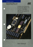
I/O Pluse II TM is a versatile and powerful data I/O
accessory for your IBM TM Personal Computer (PC) TM The real time clock
with battery backup, the RS-232 asynchronous serial communications
port, and the game adapter port (all standard), along with the optional
second serial port and parallel printer port, make the I/O Plus II the
ultimate in expansion hardware .
Research gives you two valuable utility programs . SuperDrive TM a disk emulation program allowing you to use part of your
memory as a superfast "electronic diskdrive" ; and SuperSpool T M , an
intelligent print spooler allowing you to output files to a printer
without typing up your PC TM
Compatibility
The I/O Plus II is completely compatible with the PC TM , PC-XTTM
PCTM Expansion Unit, T .1 Professional Computer, and the Compaq .
However, because the XT TM has a serial port built-in, an I/O Plus II that
is being installed in an XT TM can have only one serial port . This port
must be configured as COM2 (see section 3 .2) .
Standard Features
*A battery back-up real time clock so that you don't have to reenter the time and date every time you start your system . The
battery power is only used when your system is turned off .
*An RS-232C serial interface to be used with a MODEM, serial
printer, remote display terminal, other serial device, or as an
asynchronous communications port to another computer or peripheral operating under separate asynchronous communications
software control . (Note
a current loop teletype interface is not
supported .)
*Game adapter ports which can be used with IBM TM -compatible joysticks or Apple II-compatible joysticks .
-A-
*I/O Channel Bus Expansion for future enhancements .
Available Options
*A parallel printer port to be used for connecting a parallel printer
to the PC TM
*A second RS-232C serial port (serial #2, configurable as DTE or
DGE) to be used with a MODEM, serial printer, remote display
terminal, other serial device, or as an asynchronous communications
port to another computer or peripheral operating under separate
asynchronous communications software control .
These options may be purchased onboard, or installed by the
user at a later date . (Upgrade kits are available from your dealer .)
1 .1 "Do I Really Need to Read This Manual?"
AST recommends that you thumb through this manual at your
leisure, and read up on the Superpak software utilities .
If you have problems, you should certainly go back and read
the appropriate chapter for some helpful hints, and to clarify the
conditions necessary for your I/O Plus II card to function properly .
NOTE : BE SURE TO FILL OUT YOUR WARRANTY CARD
AND MAIL IT IN .
1 .2 System Requirements - Non-PC DOS TM Operation
All references to operating system commands in this manual
assume operation under PC DOS TM . The I/O Plus II hardware is completely IBM TM -compatible and will function properly under other
IBMTM -approved operating system software . Of course, configuring
the I/O ports under another operating system requires the use of
commands specific to that operating system . See your operating
system manual for the appropriate command syntax .
2.0 Getting Started
Before you start disconnecting cables, removing the cover,
etc ., please take the time to read this manual . Doing so will get you
acquainted with the simple procedures you will follow to properly
install your I/O Plus II . If you have a working PC TM at hand, you may
want to create a new working DOS TM diskette and copy the Super Pak
utility files to it . (See the COPY command in your DOSTM manual
for instructions .) This will save you some time when you initialize
the Clock-Calendar, SuperDrive, and SuperSpool later on . If you wish
to wait and copy these command files later on, that's fine too .
2.1 Removing the PC System Unit Cover
It takes only a few minutes to remove the cover from the PC TM
and install the I/O Plus II card into one of the empty slots in
your PC's TM system board or expansion chassis . This manual has all
the necessary instructions . Instructions for removing the cover
and setting the switches on your system board are also contained in
your IBM TM Personal Computer Guide to Operations .
CAUTION : Be sure that the power switch is off and the A .C. cord
is removed from the system unit . Turn off the printer or any other
equipment connected to the computer . Installing any component
while the power is on can permanently damage your computer and its
components .
1.
Looking at the system unit from the rear, notice the two mounting screws at the lower corners of the back panel . Remove the screws,
using a flathead screwdriver or a hex wrench .
Slide the system unit cover towards the front . When the cover
2.
will go no further, carefully tilt it upwards and remove it from the
system .
3
3 .0 Serial Asynchronous Communication Using Serial Port #1
(and Option S, Serial Port #2)
Your I/O Plus II can have one or two asynchronous communication ports . Serial # 1 is standard, and serial # 2 is optional . A serial
port handles data in a one-bit-after-another fashion, and controls
both incoming and outgoing data transmissions .
The serial port is also known as an async (asynchronous) port,
or RS-232C interface .
Its purpose is to handle non-synchronous
serial data transmission between your PC TM and a MODEM, a serial
printer, or other serial device . This is a two-way communications link .
Data transmissions "across" the link take place in a serial fashion
(one bit after another) . Multiple wires are installed between either
end of the communications link . Your PC TM serial port and the port on
the remote serial device use these wires to signal one another . This
allows data transmissions in either direction to be controlled properly .
NOTE :
An extensive discussion on wiring RS-232 interfaces is
presented in Appendix E .)
The IBM PCTM allows up to two serial communication ports, (called
COM1 and COM2) . Your I/O Plus II serial port # 1 can be set up as
either COMA or COM2 . COM1 is the default (factory) setting . PC
DOSTM recognizes COMA and COM2 as serial communication lines . The
factory default setting for the optional serial port # 2 is COM2 .
To use a communications line, you must make sure the asynchronous communications parameters (baud rate, parity, databits,
and stopbits) are properly set . This is done using the MODE command under PC DOS TM or the OPEN command under BASICA .
Consult the appropriate manual for details . An I/O Plus II serial port is
fully compatible with the parameter ranges specified by the MODE or
OPEN command (baud rate, parity, databits and stopbits) . Don't be
intimidated by these technical terms You don't need to know the
ins and outs of data communication to properly set up your serial
4
port. All you need to do is use the MODE or OPEN command to
match the parameters of your COM line to those of the remote device
Often, the remote device also has setable parameters . Consult your
manual or dealer for the best match of parameter settings .
If you change devices, be sure and change your COM line
parameter settings accordingly .
3 .1 Setting Up Serial Port # 1
Serial port # 1 has a DB25P (plug or male type) connector (J1
in Diagram A) that extends through the mounting bracket of your
I/O Plus II card .
It your present system has no serial port, the I/O Pluse II serial
port # 1 and the optional serial port # 2 are ready for use as shipped .
There is no need to alter any of the settings on the I/O Plus II . You
may skip ahead to the section entitled "Configuring Your Application
Software" . If, however, you already have a serial port in your system,
you must make several simple changes to the jumpers on your I/O
Plus II board .
3 2 If Your System Already Has a Serial Port
This discussion applies only to systems which will have more
than one serial port, in which the currently installed port is COM1 .
If your present system has a serial port (for example, an IBM TM Asynchronous Communication Adapter) you shouldn't have an I/O Plus II
with the "S" option as this would bring the total number of serial
ports up to three. The operating system only supports two serial
ports your present serial port and the I/O Plus II's standard serial #l .
There are two "Jumpers" that must be moved to change the
address of your I/O Plus II's serial port # 1 from COM1 to COM2 .
(Jumpers are pairs of wire pins that are connected or "jumped"
with small, plastic-coated blocks to complete an electrical circuit .)
The process is quick and easy, and can be performed without special
tools .
Moving the First Jumper
Place your I/O Plus II card so that the black mounting bracket is
towards the right, and find the six jumper pin pairs immediately
below the I/O Plus II trademark (see diagram on back page for clarification) .
Find the first jumper, at the top . Immediately to its
right is the designation C1. That stands for COM1 . immediately
below C1 are a pair of pins with the designation C2 (for COM2) .
Move the jumper block from C1 to C2 . Once you have done this,
you are ready to move the second jumper .
Moving the Second Jumper
Notice the edge connector at the bottom of the card . It is
about 3" long and has vertical gold "fingers" . Above the edge connector towards its left boundary are the INTERRUPT REQUEST
(IRQ) selection jumpers . The jumper positions are labeled to the
right of the pins with the designations 5C, 5S, 4, 3, 3S, 2C, and 2S .
As shipped, a jumper should be on position 4 (the IRQ line for
COM1 ). To reconfigure your serial port # 1 as COM2, you must
move the plastic jumper from position 4 to position 3 .
Your I/O Plus II serial port # 1 is now addressable as COM2 .
3 .3 RS-232 Connector Pin List for Serial Port # 1
In order to attach your PC's TM serial port to another serial device,
you must use a multi-wire cable with the proper type (make or
female) connectors at either end . In addition, you must make sure
that the proper signals are being exchanged by your PC's TM serial port
and the remote device's serial port . This is simply a matter of
matching output lines to input lines and vice versa . For example . the
pin which outputs data on the PC TM side of the link should be wired
to the pin which receives data on the other side of the link . This is
discussed in more detail in Appendix A and covered extensively in
Appendix E .
The table below lists the signal configuration used by the serial
port # 1 on your I/O Plus II . This arrangement is known as DTE (for
data terminal equipment) .
Use this information to make up the
proper cable for your particular serial communication environment .
Please make sure that pins 5, 6, and 8 (CTS, DSR, and CD) of the
DB25P (J1) connector are correctly wired to the proper incoming
signals . (See Appendix E .) The PC TM needs to "see" these signals in
order to control communications . Note that only some of the 25 pins
are used to wire the interface . You don't need to wire the unused
pins . Appendix A has specific examples of correctly cabled interfaces .
If you are using several remote devices, which require different
cabling arrangements, consider using adapter plugs to handle the line
signal routing. That way you can use the same extension cable for all
your devices and simply change the adapter plug when you change
device .
Serial Port # 1 as a DTE Interface
J1
RS232C
NAME
PIN#
AA
BA
BB
CA
CB
CC
AB
CF
CD
CE
1
2
3
4
5
6
7
8
20
22
NOTE :
SIGNAL
NAME
(Protective Ground)
TX (Transmit Data)
RX (Receive Data)
RTS (Request to Send)
CTS (Clear to Send)
DSR (Data Set Ready)
SG (Signal Ground)
CD (Carrier Detect)
DTR (Data Terminal Ready)
RI (Ring Indicate)
SIGNAL
DIRECTION
Common
OUTPUT
INPUT
OUTPUT
INPUT
INPUT
Common
INPUT
OUTPUT
INPUT
serial ports don't support a current loop type interface .
7-
3.4 Disabling Serial Port # 1
Serial port # 1 on the I/O Plus II card can be completely disabled
by removing the jumpers discussed in section 3 .2.
3 .5 Option S : Serial Port # 2
This section applies only to an I/O Plus II equipped with the
"S" option, a second serial port (serial # 2) . This is not to be confused with the parallel port option or the previous section on serial
# 1 . If your I/O Plus II doesn't include this option, it can be added
later (see User Upgrade Information) .
If you have the S option, your I/O Plus II has two asynchronous
serial communications ports . Serial # 1 has already been discussed .
As shipped, your serial port # 2 is set up as COM2 . If you have the
S option, there should definitely be NO serial ports in your PC TM
system, other than those on your I/O Plus II card. PC DOST M (or for
that matter any other current PC TM operating system) doesn't support
more than two serial ports .
3 .6 Verifying Your Serial # 2 Configuration
Your serial # 2 is factory set and ready to use as shipped . You
don't need to adjust any jumpers . Just to verify that the jumpers are
in their proper positions, let's check the positions of the two jumpers
used to control serial # 2 .
Verifying the Position of the First Jumper
Place your I/O Plus II so that the black n
to the right, and find the set of jumper pins imn
I/O Plus II trademark . A jumper block should be bridging the set of
pins third from the top, designated as S2 .
Verifying the Position of the Second jumper
Just above the edge connector at the bottom of the card are
the interrupt request selection pins (IRQ) . A jumper block should be
-S-
bridging the two pins designated as 3S .
3 .7 DTE and DCE Interface Selection for Serial # 2
Your I/O Plus II has two rows of pin connectors near the top
left corner of the card . The top row is used to set up a DTE interface ; the bottom row is used for a DCE configuration . These two
types of interfaces are discussed extensively in Appendix E . Serial
Port # 2 is configured at the factory as a DTE type interface . (This
selects the top row of pins, J2 .) In this respect, it is identical to serial
# 1, which is also a DTE interface . This type of interface is ideal
for connecting your serial # 2 to a MODEM, or other DCE type
connector .
If you have decided to use the DTE-type interface, you should
skip ahead to the section entitled "Installing the Serial # 2 Interface
Cable" .
The bottom row of pins (J3), DCE type interface, is
best used to connect your serial port # 2 to a remote printer, terminal,
or other DTE type connector .
3 .8 Setting Up Serial # 2 for DCE Configuration
The DCE configuration allows pin-for-pin wiring with a remote
DTE type port. This helps save the time and expense of constructing
a special cable for connecting like interfaces (see Appendix E) . A
jumper block selects either the DTE of DCE pin connectors (J2 or
J3). The factory configuration is DTE (J2). To use the DCE interface, find the two sets of pins below J3 . A jumper block should be
bridging the upper pin set, designated as DTE . Remove the jumper
and reinstall it so that it bridges the lower pin set, designated as DCE .
You have now selected the DCE type interface, and should install
the adapter cable on the lower row of pins, labeled J3 DCE . Installation of the adapter cable is covered in the section entitled "Installing
the Serial # 2 Interface Cable" .
3 .9 DCE Configuration :
Serial # 2 RS-232 Pin Connector Listing
Below is the pin out signal arrangement for a serial port # 2
in DCE configuration only. You can use this information if you have
to construct a special cable for your DCE type serial interface . For
more information on DCE type interface signal arrangement and
cabling, see Appendix A and Appendix E .
Serial Port # 2 as a DCE Interface
RS232
NAME
J3
PIN #
AA
BA
BB
CA
CB
CC
AB
CF
DC
CE
1
2
3
4
5
6
7
8
20
22
SIGNAL
NAME
(Protective Ground)
TX (Transmit Data)
RX (Receive Data)
RTS (Request to Send)
CTS (Clear to Send)
DSR (Data Set Ready)
SG (Signal Ground)
CD (Carrier Detect)
DTR (Data Terminal Ready)
RI (Ring Indicator)
SIGNAL
DIRECTION
Common
INPUT
OUTPUT
INPUT
OUTPUT
OUTPUT
Common
OUTPUT
INPUT
OUTPUT
NOTE : AST serial ports do not support a current loop type interface .
3 .10 Installing the Serial # 2 Interface Cable
By now you should know which pin connector (J2, DTE ; or J3,
DCE) you are going to use . If you don't, go back over the above
sections.
Examine the interface cable supplied with your S option . This
ribbon-type cable is about eighteen inches long, has a plastic
at one end, and a DB25P (plug or male type) connector at the other .
The smaller plastic connector plugs into your I/O Plus II board .
The larger "D" shaped connector attaches to the cable from your
remote serial device.
-10-
One edge of the ribbon cable is colored . This is the PIN # 1 side
of the cable . Position your I/O Plus II board so that the black mounting bracket is to your right. Now arrange the cable so that the colored
edge is towards the left end of the board . The cable should be extending towards the bottom of your I/O Plus II . Position the plastic
connector over the row of pins corresponding to the type of interface
you have selected, and gently press the connector onto that row of
pins. The connector should go on easily with an even, gentle pressure .
Routing the Adapter Cable
The adapter cable may be routed in a variety of ways . if you
have an
ConnectAII TM interface extension, you can route the
cable there and secure it through one of the available openings . If
you have an older PC TM chassis with a cut-out above the keyboard connection on the back panel, you can knock out the plug in this hole
and mount the "D" type connector to the back panel .
Another method is to simply remove the dummy bracket covering an unused expansion slot's back panel window and route the
cable out through this opening. If you choose to do this, great
care must be taken not to put a strain or any tension on your cable .
If all your expansion slots are occupied, you can use the space above
serial # 1 to route your serial # 2 adapter cable .
NOTE : It is usually more advisable to route your adapter cable
underneath existing boards, rather than over the top . The close
tolerances at the top of the PC TM may produce some wear and tear on
your cable, or worse yet, your cover may snag a cable and damage
the cable or its pin mounting .
3 .11 Configuring Your Application Software
Most communications software can be configured to send data
to either serial # 1 or serial # 2 (COM1 or COM2) . The default is
usually COM1 . But what if, for example, your MODEM is connected
to serial # 2 (COM2) and you wish to send data through serial # 2
to a remote location . It may be necessary to reconfigure your application software so that it routes the data to COM2 rather than COM1 .
In many cases, the easiest way to accomplish this is to temporarily redirect the activities of COM1 to the COM2 address . This
may be done using the MODE command under PC DOS TM . If you wish
to redirect output destined for a printer port (for example, LPT1)
to a serial port (either COM1 or COM2), the MODE command can do
this as well.
NOTE :
If you attempt to redirect data to different output
ports, be sure that the output port's parameters are properly set to
communicate with the device to which it is connected . See your
DOS manual for instructions .
If you have any questions about configuring your software,
consult the appropriate manual or software dealer .
3 .12 Disabling Serial Port # 2
Serial port # 2 on the I/O Plus II card can be completely disabled
by removing the jumpers discussed in section 3 .6.
4 .0 Parallel Printer Port (Option P)
This chapter applies to I/O Plus II boards equipped with the
parallel printer (P) option . This is not to be confused with the serial
option, discussed in chapter 3 . If your I/O Plus II card does not
include this option, it can be added latter . (See User Upgrade Information .)
The IBM PC TM allows up to three parallel printers to be attached,
called LPT1 LPT2, and LPT3 . The parallel printer port on the I/O
Plus II card is normally addressable as either LPT1 or LPT2 . When
there is an IBM TM Monochrome Display Adapter card installed in the
PCTM , the printer port on the monochrome card is always LPT1, and the
I/O Plus II card's parallel port defaults to LPT2 . It can be set to
LPT3, if desired (see section 4 .2) .
Your I/O Plus II card is configured
at the factory as LPT1 . If this is the only parallel printer port on your
system, your I/O Pluse II is ready as shipped . See 4 .2 below .
The interface to your parallel port is controlled under PC DOS TM
The MODE command allows you to configure the port's parameters
(characters per line, lines per vertical inch) . Consult your printer and
DOS TM manuals for proper parameter settings .
4 .1 Installing the Interface Cable
Place the I/O Plus II card so that the black mounting bracket is
towards the right. Near the top of the card, above the AST logo, is
the set of pins designated as J4 PRINTER PORT . (See Diagram A at
the back of this manual .)
Notice the 18-inch-long gray interface cable supplied with your
card . It has a small plastic connector at one end and a DB25S (socket
or female type) connector at the other end . The end with the small
plastic connector plugs into J4 of your I/O Plus II card . The DB25S
connector goes to your printer cable .
13-
One edge of the ribbon-type adapter cable is colored . This
marks the wire to be connected to the Pin 1 position of the set of
pins labeled J4 . Position the connector over J4 of the I/O Plus II
card so that the colored edge of the cable is towards the left . The
cable should be extending down over the board . Gently press the
connector onto the row of pins . It should slide on easily with even
pressure .
4.2 Reconfiguring Your Parallel Port for Multi-Port Systems
This section applies only if you are using more than one parallel
port .
If you have an IBM TM Monochrome/Printer Adapter card : the
printer port on the Monochrome/Printer card is LPT1 and the printer
port of the I/O Plus II automatically defaults to LPT2 . In this
particular case, no reconfiguring is needed on the I/O Plus II card .
If you already have ANOTHER (non-IBM TM Monochrome card)
parallel printer port configured as LPT1, you can reconfigure the
parallel printer port on the I/O Plus II card to function as LPT2 .
Place your I/O Plus II card so that the black mounting bracket
is towards the right . Notice the six sets of pins immediately below
the I/O Plus II trademark . A jumper block should be on the second
pin set from the bottom, designated as P1 . That stands for parallel
port 1 (LPT1) . Immediately above are two pins with the designation
P2 (for LPT2) . All you have to do is move the jumper from position
P1 to position P2 . See Diagram A for clarification .
(Note : When the above change is made, and you have an IBM TM Monochrome card, the parallel port on the I/O Plus II card responds as
LPT3 .)
14 -
4 .3 Reconfiguring Your Parallel Printer Software
IBM PC DOSTM supports three parallel printer ports . Applications
software may select any of these three ports as the output device .
The IBM DOS TM
1 .1 MODE command presently does not offer the
ability to redirect output intended for one parallel port to another .
However, a two-line code patch will allow you to internally redirect
printer part output between LPT1 and LPT2 . See Appendix B for
details .
Most PC DOS TM compatible software that sends data to a parallel
printer can be configured to send data to whatever parallel port you
specify . The default is usually LPTA . If your printer is connected to a
parallel port designated as LPT2, it may he necessary to reconfigure
your application software to address LPT2 . If you have any questions
about configuring your software, consult the appropriate software
manual or dealer .
4 .4 Printer Port Connections
You can use the information below to make a cable for connecting to an IBM TM Parallel Printer or other parallel interface . This is
a Centronics- type parallel printer interface . When wiring to other
parallel printers, check for variations . Not all printers have the same
signal line connections .
For minimal interference, you should use
twisted pairs for the cable wirings . If you are unsure how to construct
a parallel interface cable, ask your printer dealer for assistance .
NOTE : The cable supplied with your I/O Plus II card converts
the card's parallel port output into the DB25 line signal format
listed in the chart below . The J4 line outputs are supplied for reference only .
- 15 -
Parallel Port Signal Line Configuration
LINE
NAME
-STROBE
D0
DA
D2
D3
D4
D5
D6
D7
-ACK
BUSY
PE
S LCT
-AUTOFD
-ERROR
-INIT
-SL CT IN
GROUND
J4 Pin
ADAPTER CABLE
OUTPUT
DB25S
1
3
5
7
9
11
13
15
17
19
21
23
25
2
4
1
2
3
4
5
6
7
6
8
(10, 12, 14, 16,
18, 20, 22, 24)
8
9
10
11
12
13
14
15
16
17
(18-25)
IBM
MATRIX PRINTER
1
2
3
4
5
6
7
8
9
10
11
12
13
14
32
31
36
(16, 19-30, 33)
Note : A dash in front of the line name denotes lines which are functionally active when low .
4.5 Disabling the Parallel Printer Port
The parallel printer port on the I/O Plus II card can be completely disabled by removing the jumper discussed in section 4 .2,
- 16 -
5 .0 Clock-Calendar Feature
Your standard Clock-Calendar has the following features :
*24-hour clock
* Four-year calendar (no leap year)
*Battery back-up power supply (battery life, approx . one
year)
*User-replaceable Lithium battery
TM
*Full compatibility with PC DOS
*Optional CP/M-86, CCP/M-86, and p-System clock utility
software available (See your dealer)
The Clock-Calendar feature answers the TIME and DATE
prompts which the DOS TM operating system issues each time you boot
the system .
The lithium battery is easily replaceable and should last for
about a year . The clock chip on your I/O Plus II is powered by the
PC system when your PC is on . The battery is used as back-up power
while your PC TM is off . To replace the battery, slightly lift the retaining
clip with your finger and use a small screwdriver to remove the
battery from its holder. Replacement batteries can be purchased from
the factory or your local watch or appliance store . (Part number
Panasonic BR2325)
Take care not to damage or bend the retaining clip by lifting it
too far . The clip completes an electrical circuit and must make
solid contact with the positive (+) side of the battery . When installing
a new battery, make sure it is clean and dry .
5.1 Initialization
To initialize the clock-calendar feature (after you have installed
your I/O Plus II card), copy the two clock programs, ASTCLOCK .
COM and SETCLOCK .COM to your working DOS TM diskette. These
programs are on the SuperPak diskette supplied with your I/O Plus II .
Your working DOS TM diskette must contain the usual DOS TM clock
programs . If you are unsure how to COPY a file or how to create an
AUTOEXEC .BAT file, consult your DOS TM manual .
Now, add the ASTCLOCK program to your AUTOEXEC.BAT
file . ASTCLOCK is a utility program which reads and displays the
current time and date from the I/O Plus II at each power up or
reboot of the system . It then exits to DOS TM ("A > ") when finished .
The following sequence of commands will create an AUTOEXEC.
BAT file to automatically set the time and date for you every time
you turn on or reboot the computer :
COPY CON : AUTOEXEC. BAT < enter >
ASTCLOCK < enter >
Function key F6 < enter >
Your AUTOEXEC.BAT file may contain other commands in addition
to running ASTCLOCK .
5 .2 Setting the TIME and DATE
You need to execute the SETCLOCK utility whenever you want
to update the time or date of the I/O Plus II board's internal clock .
TIME and DATE commands only update the system's
The DOS TM
time and date parameters ; they will not update the time and date
values stored in the I/O Plus II clock chip .
To set the clock on your I/O Plus II (remember, the SETCLOCK
program must be on your DOSTM diskette) , type in the following
instruction
SETCLOCK < enter >
The system will display the current date and time . Typing DATE and
TIME allows you to update these values in the I/O Plus II's clock chip .
When you are done, press keys Ctrl and Alt simultaneously, and hold
while pressing Del (reboot) to exit the SETCLOCK utility . (Note :
The REBOOT is required to set the I/O Plus II clock parameters .)
If you replace the battery, be sure to use the SETCLOCK procedure to restore the proper time and date .
5 .3 Device Addressing of the Clock-Calendar
This technical information is for reference only : you do not
need to read this section to use the Clock-Calendar feature . The
clock-calender is at I/O address hexadecimal 2C0 and uses 32 contiguous locations for programming functions. See Appendix C for a
breakdown of programming functions and locations .
-19-
6.0 Game Adapter Port
In order to be able to use either an IBM TM -compatible joystick or
Apple II joystick (s), three game adapter ports (joystick connectors)
exist on the I/O Plus II card .
6.1 Mounting the Connectors
If you Have an IBM TM
Type Joystick,
Place the I/O Plus II card so that the black mounting bracket
is towards the right . Near the top left corner of the card is the set of
pins designated as J7 (see Diagram A) .
Notice the interface cable supplied with your card . It has a
small plastic connector at one end and a DB15S (socket or female
type) connector at the other end . The end with the small plastic
connector plugs into J7 of your I/O Plus II card .
The cable is routed through an expansion slot in the rear panel
of the PC TM to connect to the IBM TM joystick cable . If you have an
ConnectAII TM , you can mount the DB15S connector in the DB15
slot in the bracket where it can be connected to the joystick cable .
Position the connector over J7 . Make sure that pin 1 on the cable
is matched up with pin 1 on J7 . (Pin 1 on J7 is designated by a "1 " ;
the V-shaped notch on the cable's connector means that pin 1 is on
that corner.) The cable should be extending to the right, over the
board . Gently press the connector onto the row of pins . It should
slide on easily with even pressure .
If you Have Apple II Type joystick (s)
Locate the two sets of pins in the top left corner of the card,
designated as J5 and J6 . The cables for the joysticks can be plugged
into both J 5 (joystick A, buttons A1 and A2) and J6 (joystick B,
buttons BA and B2) . If you have only one joystick, the cable can be
plugged into either J5 or J6 . Pin 1 on both J5 and J6 is designated by
a "1 ". Make sure pin 1 on the port matches up with pin 1 on the
cable (designated by a dot above the pin) . The cable(s) should be
routed through an expansion slot in the rear panel of the PC TM . With
some cables, you may have difficulty passing the connector through
the slot ; the connector may need to be disassembled first .
When using Apple II type joystick(s), a user-supplied IC1 (74LS
#5) must be plugged in on U1 . U1 is located immediately below
J6 (see Diagram A) . IC1 must be removed when using an IBM TM type
I BM TM type joystick .
Note :
When plugging in the IC, make sure that the notch on the
IC matches the position of the notch in UA . This will ensure that pin
1 is positioned correctly .
6 .2 Configuration
In order to enable the game hardware, all of the required parts
must be installed and a jumper should be inserted in the configuration
programmer .
Place the I/O Plus II card so that the black mounting bracket is
towards the right, and find the six jumper pin pairs immediately
below the I/O Plus II trademark . You should place a jumper so that
it bridges the bottom set of pins, designated as G .
6.3 Reconfiguring Your Software
The game port is totally software-compatible with the IBM TM
game adapter when using the lBM TM type joystick .
Apple II type joysticks return slightly different values . However,
since most quality software allow for centering of the sticks upon
initialization, this should present little difficulty .
- 21 -
Note :
Since there are a always variations among joysticks, some
software may not function properly, regardless of whether IBM TM or
suggests that
Apple II type joysticks are being used . Therefore,
you buy only quality software and make sure that a joystick-centering
function is provided .
6 .4 Device Addressing of the Game Adapter
This
The game adapter is at I/O address hexadecimal 201 .
technical information is for reference only ; you do not need to
know this to use the game adapter .
6 .5 Disabling the Game Adapter Port
The game adapter port on the I/O Plus II card can he completely
disabled by removing the jumper discussed in section 6 .2 .
7 .0 Installing Your l/O Plus II Card
The I/O Plus II card can be inserted in any one of the five expansion slot receptacles on the PC TM system board .
BE SURE THE POWER IS OFF AND THE POWER
CAUTION :
CORD IS REMOVED FROM THE PC BEFORE INSTALLING OR
REMOVING ANY EQUIPMENT .
I.
Select a free expansion slot, and find the black metal bracket that
covers the cut out in the back panel of the PC TM chassis . Remove
and save the bracket-retaining screw using a small flathead screwdriver . Remove the bracket .
2.
Line up your I/O Plus II card and position its front bottom
corner in the card guide channel . Keeping the top of the I/O
Plus II level, lower the I/O Plus II until its edge connector is
resting on the expansion slot receptacle . Using an evenly distributed pressure, press the I/O Plus II straight down until it
seats in the expansion slot . Replace the bracket-retaining screw
that was removed in step 1.
3.
(Parallel printer and/or serial #2 options only) If your PC TM has
a cut out above the keyboard connector on the rear panel, route
the adapter cable(s) under all the cards and out to the cut out .
The cut out's plastic cover can be removed easily by pressing
it towards the rear .
1
If your PCTM does not have the cut out, your can route your
cable(s) through the gap at the top of the mounting bracket . The
end of the cable(s) can be attached to the optional AST "ConnectAll"
mounting device for a neat, secure installation .
4.
It is now time to check to see if everything works . You can
replace the system unit's cover prior to check out or you can
wait until later . To replace the cover, carefully slide the cover
from the front until it stops securely against the rear panel .
Reinstall the two screws you removed earlier from the lower
corners .
5.
Replace the power cord to the system unit and be sure that
the keyboard and the monitor connectors are plugged in .
7.1 Testing the New Installation
1.
Insert a DOS TM diskette in drive A,
and turn on the power . If
everything was done correctly, the system will boot as normal .
2.
Run the IBM TM diagnostic routines to check out the features you
have just installed . See your Guide to operations manual for
instructions . Note : The diagnostic routines do not test the
Clock-Calendar feature .
3.
After you have finished the diagnostic routines, insert the DOS TM
diskette that you have installed with the AUTOEXEC .BAT tile .
Reboot the system (press Ctrl and Alt simultaneously and hold
while pressing Del) . The ASTCLOCK program should come up
and display the current time and date . In most cases the clock
should give the correct time with the exeception of time zone
differences . Use the SETCLOCK program to set/reset the clock
on your I/O Plus II .
-- 24 -
8 .0 User Upgrade Information
The I/O Plus II card is designed to allow easy user upgrade . To order
the optional items, please use the following part numbers .
Serial Option
Order part number IO-000S for async communication (RS-232)
upgrade kit which consists of a UART, interface ICs, adapter cable,
and documentation .
Parallel Printer Option
- Order Part number IO-000P for parallel printer upgrade kit which
consists of all the necessary ICs, printer adapter cable, and documentation .
Diagnostic Programs
Order part number IO 199 for the comprehensive I/O Plus II
diagnostics which test async port (COM1 and COM2), parallel
printer port (LPT1 and LPT2), Clock-Calendar, and game adapter
port.
Note : Although the
I/O Plus II card is designed for easy user
expansion, the warranty coverage applies only to the configuration
of the board as originally shipped from the factory . The expansion
sockets and any additional expansion-related components are not
warranted .
- 25 -
Appendix A
Recommended Serial Port Cabling
This section contains pin connections and wiring configurations
for interfacing the serial port on your I/O Plus wiring other product
interfaces, consult Appendix E of this manual and your serial device's
manual, or call your printer manufacturer and tell them you wish to
connect to an IBM PCTM Asynchronous Serial Port . Your I/O Plus II
serial port is compatible with the IBM serial port .
***DTE Type Cabling***
The following interface diagrams refer to DTE interfaces only .
Suggested wiring to MODEM devices (Haye Stack Smart MODEM,
Novation Cat, UDS, etc) :
I/O Plus II
MODE
Serial Port
Port
Connector
Connector
2 ---------------------------- 2
3 ------------------------ 3
4
4
5 --------------------------- 5
6 ---------------------------- 6
7 ----------------------------- 7
g
8
20
20
22
22
Use a DB25S (female/socket) connector for the I/O Plus II side and
a DB25P (male/plug) connector for the MODEM side.
- 26 -
Suggested wiring for NEC 7700 series, TI 810 ser ies, Epson MX-100-3 and Brother HR - 1 series printers :
I/O Plus II
Serial Port
Connector
Printer
PortI
Connec tor
- ----------------------- ----- 1
----------------------------- -- ---- -------- 3
---- ---------------------------------------- 2
------------------------- --------------------------- 11
TI, Brother ; Epson only 5 ------------------- -5 ----------------19
NEC printer only
6, 8 20
7 --------------------------- ---------------- 7
20 --------------------------------------------- 6, 8
1
2
3
.4
Pins 6 and 8 on the PC TM side are wired together and connected to
pin 20 from the printer . T he same is true in the "other direction" .
This wiring allows the printer to inform the PC TM that its receiving
buffer is full . Use a DB 25S (female/socket connector for the I/O
Plus II serial port and a DB25P (male/plug) for the printer . If you
have a printer like the NEC 7720 (which requires a DB25S), you will
need to use an adapter to hook up to the current .
Suggested wiring for the Qume Sprint 9/45, 9/55 printers :
- 27 -
Suggested wiring for the Qume Sprint 9/45, 9/55 printers :
!/{] Plus 11
Serial Port
Connector
1---
Printer
Port
Connector
--1
-3 2-
3- ----2
4 ---5
5
20
6, 8 -- 4
7- ---7
20
6, 8
This wiring allows the Qume printer to inform the PCTM that its
receiving buffer is full . []5c DB25S (female/socket) for the 1/0 Plus 11
scrial port and a OB25P/rna!e/p)ug\ for the [kurnt printer .
Suggested wiring for CRTs and printers running at low baud rates
(110-300) :
I/O Plus IICRT/Printer
Serial Port
Conneaor
Port
Connector
1 - 1-
2-----3
3 . 2
7 ----------7
___
4,5
6, 8 - 20
- - 5, 20 or 4, 5 if
needed
This wiring does not use standard EIA RS-232C handshaking ; however, it should work with most CRTs and some printers . Use DB25S
(female/socket) for the I/O Plus II serial port and a DB25P male/plug)
for the CRT or printer (in most cases) . Notice that pins 5 and 20, or
4 and 5 on the CRT side can he wired together . Consult the user's
manual for your CRT or printer for your specific configuration .
Suggested wiring for the Diablo *620 printer :
I/O Plus II
Serial Port
Connector
1
2
3
5
7
6
20
Diablo 620
Serial Port
Connector
------------------------------------------ 1
--------------------------------------------- 3
----------- -------------------------------- 2
-------------------------------------------- 4
------------------------------------------ 7
, 8 20
-------------------------------------------- 6
This arrangement allows the Diablo to inform the PC T M side of the
interface that its receive buffer is full . Notice that pins 6 and 8 on
the PC TM side are wired together, and then commonly connected to pin
20 on the Diablo 620 side .
Suggested wiring for the Smith-Corona TP-1 :
I/O Plus II
Serial Port
Connector
1
2
3
4
5
6
7
Smith-Corona
Serial Port
Connector
------- --------------------------------------------------------------------------------------------------------------------------------------------------------------------------------------------------------------, 8, 20
---------------------------------------------
1
3
2
5
4
7
6 . 8, 20
This at arrangement gives theTP-1suficntorlveOutpfrom
the PCTM side of the interface . Notice that pins 6, 8 , and 20 are connected to each other on either side art the link . This allows both
devices to remain in a ready state, while pins 4 and 5 actually control
the flow of data from one side to the other .
Appendix A (Continued)
2
*** DCE Type Cabling'**
5
The following interface diagrams refer to DCE interfaces only .
Suggested wiring to MODEM devices (Haye Stack Smart MODEM,
Novaton (at
,
UDS, etc
I :
I/O Plus II
MODEM
Serial Port
Port
Connector
Connector
1 -------------------------------------------- 1
--------------------------------------------- 2
3 --------------- ------------------- --------- 3
4 --------------------------------------------- 4
--------------------------------------------- 5
6 -------------------------------------------- 6
7 -------------------------------------------- 7
8 -------------------------------------------- 8
20 22 20
22
Use a DB2SS (female/socket) connector for the I/O Plus II side and a
DB25P (male/plug) connector for the MODEM side .
Suggested wiring for NEC 7700 series, TI 810 series, Epson MX-100-3
and Brother HR-1 serial printers for serial # 2 in DCE configuration :
Printer
Port
Connector
I/O Plus I I
Serial Port # 2
Connector
2 ---------------------- - ------------ 2
3
3 1
Tl, Brother, Epson only 4 -------- -------------------- -----------NEC printer only
4 -------------------------------------------- 19
5
5 6 7 20 6
7
20
This wiring allows the printer to inform the PC TM that its receiving
buffer is full . Use DB25S (female/socket) connector for the I/O Plus
II serial port and a DB25P (male/plug) for the printer .
Suggested wiring for the Qume Sprint 9/45, 9/55 printers to the
serial # 2 in DCE configuration :
I/O Plus II
Serial Port # 2
Connector
Printer
Port
Connector
2
3
4
5
6
7
20
4
-------------------------------------------- 2
-------------------------------------------- 3
------------------------------------------- 20
------------------------------------------ 5
-------------------------------------------- 6
------------------------------------------ 7
---------------------------
This wiring allows the Qume printer to inform the PC TM that its receiv-
- 31 -
ing buffer is full . Use a DB25S (female/socket) for the I/O Plus II
serial port and a DB25P (male/plug) for the Qume printer .
Suggested wiring for CRTs and printers running at low baud rates
(110-300) to the serial # 2 in DCE configuration :
I/O Plus II
Serial Port # 2
Connector
CRT/Printer
Port
Connector
2
3
7
4, 5
20
---
2
3
7
20
5, 20 or 4, 5 if
needed
This wiring does not use standard EIA RS-232C handshaking ; however, it should work with most CRTs and some printers . Use DB25S
(female/socket) for the I/O Plus II serial port and a DB25P (male/
plug) for the CRT or printer (in most cases) . Notice that pins 5 and
20, or 4 and 5 on the CRT side can be wired together . Consult the
user's manual for your CRT or printer for your specific configuration .
Suggested wiring for the Diablo 620 printer :
I/O Plus I I
Serial Port
Connector
1
2
3
5
7
6
20
Diablo 620
Serial Port
Connector
---- ------------------------------------ --- 1
---------------------------------------- 3
------------------------------------------ 2
-------------------------------------------- 4
----------------------------------------- 7
20
6
- 32 -
2 2
This arrangement allows the Diablo to inform the PC TM side of the
interface that its receive buffer is full . Notice that pins 6 and 8 on
the PCTM side are wired together, and then commonly connected to pin
20 on the Diablo 620 side .
Suggested wiring for the Smith-Corona TP-1
I/O Plus II
Serial Port
Connector
Smit-Cornona
Serial Port
Connector
2
3
4
5
6, 8, 20
7
5
4
7
6 , 8, 20
This arrangement gives the TP-1 sufficient control over output from
the PC TM side of the interface . Notice that pins 6, 8, and 20 are connected to each other on either side of the link . This allows both
devices to remain in a ready state, while pins 4 and 5 actually control
the flow of data from one side to the other .
Appendix B
Switching Between LPT1 and LPT2
The following program can be used in the BAT mode to direct
printer output, normally designated for the device attached to port
LPT1, to instead be routed to the device attached to port LPT2 . (The
program also directs output, normally designated for the device
attached to port LPT2, to instead be routed to the device attached to
port LPT1.)
This can be used when your LPT1 printer (call it printer # 1)
is down for service, or when you desire, say, the type style or speed
of the printer attached to LPT2 (call it printer # 2) . This program
allows you to quickly switch between outputs without having to
alter your hardware interface or change each line in programs where
LPTI or LPT2 appear as your output port designation .
If your printers are not configured to the same parameters,
as defined in the PC DOS TM MODE command, it will be necessary to
add two MODE statements when switching devices .
You will note that the "swap" program below is written in
BASIC . Since the printer port swap is best handled in DOS TM , it is
necessary to invoke BASIC within the BAT file . No RUN command
is required when the BASIC all and the program file name occur
on the same line .
The following batch file and BASIC program will redirect printer
output from LPT1 to LPT2 or vice versa, depending on which port
is being used at the time .
LPTSWAP.BAT (or a name of your choosing) with the following :
MODE LPT1 : [parameters for printer # 2 (if needed)]
MODE LPT2 : [ parameters for printer L 1 (if needed)
]
BASIC LPTSWAP
- 34 -
LPTSWAP is a BASIC file, as below . The comments are included
for clarification and should not he included in the actual program :
10
20
30
40
50
DEF SEG = &H40
A = PEEK (8) : B = PEEK (9)
POKE 8, PEEK (10) :
POKE 9, PEEK (11)
POKE 10, A : POKE 11, B
SYSTEM
finds port address table
: save I PT 1 address
LPT2 address to L P T I
: LPT1 address to LPT2
return to DOS TM
To restore LPT1 to LPT1 AND ALSO to restore LPT2 to LPT2
Use the same program, LPTSWAP, to restore your parallel printer
ports to their original arrangement . Be sure to restore the proper
parameters using a new batch file and MODE statements .
LPTRSTR .BAT is as follows :
MODE LPT1 : [parameters for printer# 1 (if needed)]
MODE LPT2 : ( parameters for printer # 2 (if needed) ]
BASIC LPTSWAP
Appendix C
I/O Addressing : Clock-Calendar Chip - MM58167A
I/O Address
Offset
00
01
02
03
04
05
06
07
08
09
0A
0B
0C
0D
0E
0F
10
11
12
13
14
15
16
1F
Function
counter-A /10000 of seconds
counter-A /100 and 1 /10 seconds
counter-seconds
counter-minutes
counter-hours
counter-days of the week
counter-day of the month
counter-month
RAM-year
RAM-year
RAM-year
RAM-not used
RAM-not used
RAM-not used
RAM-not used
RAM-not used
interrupt status register
interrupt control register
counter reset
RAM reset
status bit
GO command
standby interrupt
test mode
Counter and RAM reset format
Data
01
02
04
08
10
20
40
80
Function
1 /10000 of seconds
1 /100 and 1 /10 of seconds
seconds
minutes
hours
days of the week
day of the month
month
Clock-Calendar base port address : 2C0
Appendix D
General Procedure for Applying Patches
A patch is a short program which alters the way the operating
system usually handles a particular situation .
recommends
the following procedure for applying "patches" :
Create a DOS TM diskette which contains the DEBUG utility and
the program to be patched . (Your DOSTM manual explains the use and
function of the DEBUG utility .) Place this disk in drive A and hoot
the computer . After the patch is applied, the new (patched) version
can be copied over to your working diskettes . DO NOT APPLY
PATCHES TO YOUR MASTER DISKETTES USE BACKUPS
ONLY! TEST THE PATCHED VERSION BEFORE ACTUALLY
USING IT!
In the following procedures, the user enters all boldface text,
exactly as shown ; BE SURE TO INCLUDE SPACES . Terminate each
entry line with the ''enter'' key . The computer responds with all
other output . Refer to your DOS TM manual for more information on
using the DEBUG commands .
SuperSpool Printer Status Errors
When running SuperSpool versions 1.00 and 1.01 (diskette P/N 210- 160-2, 210-1160-2 .1, and 210-1160-2 .2) with certain application
programs, a "Printer Not Available" error sometimes occurs . The
following patch to your SuperSpool program will correct this .
A > debug superspl.com
-e 17c
04FA :017C
- e 19e
04FA :019E
-w
2A.b4
E4 .90
2A.b4
E4 .10
38
Writing 1555 bytes
-q
A>
Patch for DOS TM 1 .1 Version of DISKCOMP Utility
The DOSTM 1 .1 version of the DISKCOPY utility has a bug in it which
only manifests itself when the user has a large amount of memory
(enough to hold an entire double sided disk) and double sided disk
drives . DISKCOPY will get into an error loop and try to read past
the end of the source drive . The following patch will correct the
problem.
A > debug diskcopy .com
-e861 e8 74 00
-e8d8 3d 51 00 72 02 b0 50 a2 36 05 c3
-rcx
CX 07D8
-7e3
-w
Writing 07E3 bytes
-q
A>
Patch for DOS TM 1 .1 Version of DISKCOMP Utility
The DOS TM 1 .1 version of the DISKCOMP utility contains a bug which
will prevent successful operation when the user has a large amount
of memory and double sided drives . The following patch will correct
this problem .
A > debug diskcomp .com
-e6eC 38 79 00
-e768 3d 51 00 72 02 b0 50 a2 95 04 c 3
39
-rcx
Cx 0668
:673
-w
Writing 0673 bytes
-q
0673
bytes
A>
Pre-configuring DOSTM 1 .1 Version for Pour Drives
The following sequence of commands will patch DOS TM Version 1 .1
so that it thinks there are always four disk drives in the system, regardless of the setting of system switch #1, positions 7 and 8 . This
patch applies ONLY to DOS TM 1 .1 . Once it is made, take care to distinguish this version of DOS TM from the normal version .
Pre-configuring DOS TM 1 .1 Version for Pour Drives
The following sequence of commands will patch DOS Version 1 .1 so
that it thinks there are always four disk drives in the system, regardless of the setting of system switch # 1, positions 7 and 8 . This
patch applies ONLY to DOS TM 1 .1 . Once it is made, take care to distinguish this version of DOS TM fr om the normal version .
A >DEBUG
--L1000 0 7 2 OR L100 0 142 2 if double sided drives
-034F
04FA : 034F D0.2B (SPACE - DEBUG GOES TO NEXT LINE)
04FA : 0350 C0.C0 25 .06 03 .8E 00 .C0 75 .80 06 .0E 06 .10
06 .04
04FA : 0358 01 .C0 04 .07 01 .B8 40.04 40 .00
-w100 0 7 2 OR W100 0 142 2 if double sided drives
-Q
A>
Re boot computer .
40
Appendix E
TM
Wiring Your PC
Serial Port to Remote Serial Devices Using the
Electronic Industry Association RS232C Standard Interface
Research carefully designs its RS-232 interfaces to ensure
that the PC's TM operating system software and hardware will utilize
the serial port in a manner consistent with IBM's TM notions of what
the serial port should "look like" to the system . In addition,
designs its products so they are easy to reconfigure . For example,
there is no etch cutting or soldering required to reconfigure a serial
port from COM1 to COM2 . To make this change you simply move
two jumpers to different pairs of pins .
The EIA RS-232C standard describes the arrangement of control
and data signals on both sides of a serial communications interface .
As a reference point to model the standard on, the RS-232 document
describes an ideal case it which a data terminal is connected to a
MODEM . A MODEM is a MOdulator/DEModulator used to connect
a terminal to a communications device . The communications device
interfaces to a transmission medium (for example, phone lines)
which carry the signal to a similar device connected to a port on
another DTE port or the communications element of a mainframe
computer system (either of which we can call the "remote") .
The EIA standard provides for various signals to be sent between
a data terminal (DTE) and a data communications device (DCE),
to control the exchange of data to and from the local MODEM and
local terminal . These signals travel on separate wires from pins on
the DTE side (terminal) to pins on the DCE side (MODEM) .
For asynchronous applications such as your
card serial
port, we are interested in the "states" of only eight or nine (of the
twenty-five possible) wires between the DTE (your PC TM port) and the
DCE (a MODEM or serial printer DCE port) .
Let's look at an ideal case set up first so that you will become
acquainted with the signal and sequence requirements of the RS-232
standard . In our ideal case scenario, we'll imagine we are connecting
the serial port on your
card (DTE) to a telephone MODEM
A correctly configured DCE/DTE interface will be wired
(DCE) .
"straight across" ; i .e ., pin 20 on the DTE side will be wired to pin 20
on the DCE side, pin 2 to pin 2, and so forth . Let's see what sort of
"handshaking" (the manner in which two devices are set to interact
so as to function properly has to take place .
When the DTE serial port on your PC TM wants to trasmit some data
it raises the voltage, or "brings up", pin 20 which is known as DTR
(data terminal ready) . This voltage travels to pin 20 on the DCE
side where, ideally, the DCE MODEM tells itself that a communications link is being requested by the terminal device . Assuming that
an open phone line exists, the DCE brings up two lines on its side of
the interface ; DSR (data set ready, pin 6) and DCD (data carrier
detect, pin 8) . When the DTE (remember, that's your PCTM port) sees
voltage at its pins 6 and 8, it is free to bring up pin 4, RTS (request
to send) . This tells the DCE, in effect, that ''I've got data to transmit
to you right nowl" The DCE checks to make sure it is ready to
receive data and, if so, brings up pin 5, CTS (clear to send) . The
DTE, seeing voltage on its pin 5, starts transmitting on the wire
connected to pin 2, TD (transmit data) . Any incoming traffic is
received at pin 3, RD (receive data) . (NOTE : some MODEMs have an
automatic answer mode which uses pin 22, the Ring Indicator (RI)
to alert the terminal that incoming data is due . The terminal responds
with DTE .) One other thing : be sure to wire pins 1 and 7 . They are
ground wires and can help protect your equipment from damage .
Figure A, below, shows which signals are used between the DTE
and DCE and in which "direction" they travel .
Figure A
The Ideal : Terminal to MODEM
PCTM Side
Signal
MODEM Side
Pin #
DTE
Pin #
Signal
DCE
Ground
1
1
Ground
Ground
7
7
Ground
(RI)
22
22
(RI)
DTR
20
20
DTR
DCD
8
8
DCD
DSR
6
6
DSR
RTS
4
4
RTS
CTS
5
5
CTS
Tx D
2
2
TxD
Rx D
3
3
Rxd
Notice that the INPUT signals on the DTE side of the interface
are DCD, DSR, CTS, and RxD . Also, the DTE has OUTPUT DTR,
and RTS . These are the signals which must be handled by the interface before the DTE can transmit or receive data .
Now notice the SEQUENCE in which these signals occur (top
to bottom in Figure A) . From the DTE's standpoint, he must send
DTR, see DCD, see DSR, send RTS, and see CTS before he can
transmit or receive data . That is, the INPUTS must have voltage
applied to them or the interface cannot become operational . (The
outputs matter only in that they are inputs to the DCE side of the
interface .) The hardware which controls the DTE serial interface will
not release data to the communications link until the proper set
and sequence of signals has been received.
One other concept : you can think of certain pins on one side of
the interface as being "functional pairs" When the
serial port
sends DTR, it expects to see DSR (and DCD) raised in response . DTR
and DSR are signal and response to one another . For this reason we
will think of them as a pair . The same is taken up again later in our
discussion .
NOW LET'S LOOK AT A TYPICAL (NON-IDEAL) CASE
DTE to DTE Interfaces
As is often the case, many devices, such as serial printers, are set
up as DTEs . To output data from your PC TM serial port (also DTE)
to a serial printer or other DTE device requires the wiring of a DTE to
DTE interface . Such an interface must fool each side of the link into
thinking that it is receiving "response" inputs from a DCE . As
mentioned above, not only must the input voltages be present, but
they must become present in the correct sequence (although, this
varies from device to device) .
To illustrate, let's look at the case presented in Figure B .
44
Figure B
Example of a Specific DTE o DTE Interface
PCTM Serial
Qume Sprint 9/45
Serial Printer
Port Side
Signal
Pin #
Pin #
Signal
DTE
DTE
Ground
1
1
Ground
Ground
7
7
Ground
DTR
20
20
DT R
DCD
8
8
DCD
DSR
6
6
DSR
RTS
4
4
RTS
CTS
5
5
CTS
Tx D
2
2
TxD
Rx D
3
3
Rx D
Notice that the necessary input signals have been supplied to
both sides . DCD, DSR, and CTS have voltage applied to them on
either side . The integrated circuit which controls the PC TM side (IRS 8250) is fairly flexible in reading the sequence of inputs . That is why we
can "drive" CTS with DTR from the printer's side . You'll notice that
this is the only sequencing rule that we've broken . Why have we done
this? The Qume manual explains that when the printer's receive
buffer is about to fill up it "drops" its DTR signal . Since we don't
want to lose data by overflowing the printer's receive buffer, we need
-- 4 5 --
to immediately halt the output of data from the PC TM side of the
interface . The best way to do this is to immediately drop the clear to
send (CTS) input on the PC TM side . By having the printer's DTR output
drive the PC'sTM CTS input, we can ensure that this kind of control will
occur . The remainder of the interface will "idle'' until the printer
"raises'' DTR again . (Remember, this is a specific case for Qume
serial printers .)
Let's look at another example of intefacing a serial DTE printer
to the PC's
card serial port .
Figure C
Serial Port DTE fo NEC 7700 Series Serial DTE Printer
PCTM Serial
NEC 7700 Series
Printer Side
Port Side
Signal
Pin
Pin »
Signal
1
Ground
Ground
1
Ground
7
7
Ground
DTR
20
20
D T R
DCD
8
8
DCD
DSR
6
6
DSR
RTS
4
19
SRTS
CTS
5
TxD
2
2
RxD
3
3
CTS
46
TxD
RxD
in this case, the printer uses line 19, a Secondary Request to
Send (SRTS), instead of pin 4 . Other than this oddity, careful examination of the interface will show that all of our DTE input and
sequence rules have been followed . On both sides DCD, DSR, and
CTS are raised, and in the top-down sequence we are generally, trying
to follow for these signals .
Another nice thing about this particular wiring is that all of the
pins are driven by their functional counterparts on the other side of
the interface . you'll recall in our Ideal Case scenario we mentioned
functionally related ''pairs'' of pins .
( DTR/DSR, DTS/CTS, and
TxD/RxD .) Figure C shows that an element of a pair on one side
of the interface, is driving its partner element on the other side of
the interface . When sequence is im portant, this is a good way to tell
if your Interface . When sequence is important, this is a good way
to tell if your interface will work or not .
47
I


