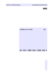
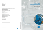
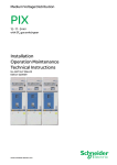
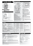
1
Gas-Insulated Switchgear GHA Gas-Insulated Switchgear Camera system for isolating and earthing switch (Single Busbar Panels) (Supplement to the operating manual) No. AGS 531 059-01 Edition 09/2014 www.schneider-electric.com Manufacturer: Schneider Electric Sachsenwerk GmbH Rathenaustrasse 2 D-93055 Regensburg Germany ( +49 (0) 9 41 46 20-0 7 +49 (0) 9 41 46 20-418 Service: Schneider Electric Sachsenwerk GmbH Rathenaustrasse 2 D-93055 Regensburg Germany ( +49 (0) 9 41 46 20-777 7 +49 (0) 9 41 46 20-418 GHA Contents Remarks on this manual.............................................................................. 4 Purpose and target group............................................................................................ 4 Reference documents................................................................................................. 4 Terms and symbols used............................................................................................. 4 Disclaimer of liability.................................................................................................... 5 Any questions or suggestions?................................................................................... 5 1 Safety provisions............................................................................... 6 2 Specifications for the camera system.............................................. 7 3 Installing the User-Software and the USB driver............................ 9 4 Monitoring System........................................................................... 14 5 Camera replacement........................................................................ 26 2.1 2.2 2.3 2.4 3.1 3.2 3.3 3.4 4.1 4.2 4.3 4.4 4.5 4.6 4.7 AGS 531 059-01 | Edition 09/2014 Technical data of the camera system............................................................... 7 User guidelines for operating the camera system............................................ 7 SCHNEIDER ELECTRIC SOFTWARE LICENSE TERMS.............................. 8 Trademark Acknowledgments.......................................................................... 8 Package content.............................................................................................. 9 Computer system requirements....................................................................... 9 Installing the User Software............................................................................. 9 USB driver...................................................................................................... 13 Starting the monitoring system....................................................................... 14 Monitoring system for three position switch................................................... 15 Monitoring system for busbar earthing switch................................................ 19 Monitoring system for busbar voltage transformer......................................... 21 Monitoring system for busbar surge arrester................................................. 23 Changing to another USB view port............................................................... 25 Closing the monitoring system....................................................................... 25 3 GHA Remarks on this manual As our products are subject to continuous development, we reserve the right to make changes regarding the standards, illustrations and technical data described in this Technical Manual. Purpose and target group This technical manual is a supplement to the operating manual GHA. This Documentation describes a Camera system for the three positions switch in a busbar compartment. The three positions switch comprise the function: ■■ Isolating switch ■■ Earthing switch The work described in this manual may only be performed by specialist electricians with proven experience regarding ■■ the GHA series (training certificate) ■■ all relevant safety provisions. These instructions are an integral part of the product and must be stored so that they are readily accessible and can be used by persons who are working on the switchgear. If the switchgear is relocated, it must be accompanied by this documentation. This technical manual cannot describe all imaginable cases or every customized version of the product. For information which is not included in this manual, please contact the manufacturer. Reference documents This technical manual is complementary to the following: ■■ Purchase contract with the agreements on the configuration of the switchgear and with legal details ■■ Operating Manual GHA ■■ the switchgear circuit diagrams / documentation Terms and symbols used This manual uses certain terms and symbols. They warn about dangers or provide important information in order to avoid danger to personnel and damage the equipment: "Danger!" This danger symbol warns about dangerous electrical voltage. Contact may result in fatal injury! "Warning!" This danger symbol warns about the risk of injury. Follow instructions to avoid death or serious injury. "Important:" This instruction symbol is used for information which is important to avoid material damage. 4 AGS 531 059-01 | Edition 09/2014 GHA Remarks on this manual Disclaimer of liability The manufacturer shall not be held responsible for damage which occurs if: ■■ instructions in this technical instruction are not followed, ■■ the switchgear is assembled, connected or operated incorrectly, ■■ accessories or spare parts that are used have not been approved by the manufacturer, ■■ the switchgear is modified without the manufacturer's approval, or if unapproved parts are attached. No liability is accepted for parts provided by customers. Any questions or suggestions? Do you have any questions or suggestions regarding this manual, or do you require further information? We always strive to provide you with the best information for optimum safe use of our products. Thus, do not hesitate to contact us if you have any recommendations, amendments or proposals for improvement. AGS 531 059-01 | Edition 09/2014 5 GHA 1 Safety provisions The work described in this manual may only be performed by specialist electricians who have proved their experience with the GHA series (training certificate) and the applicable safety provisions. Read the whole manual carefully before working on the switchgear. Applicable standards and regulations: ■■ Metal-enclosed AC switchgear for rated voltages > 1kV up to including 52 kV: IEC 62271-200 ■■ The locally applicable accident prevention, operating and work instructions must be followed. ■■ Assembly and maintenance: IEC 61936-1 / EN 505221 ■■ Operation of electrical equipment: EN 50110-11 The national standards applicable in the country where the equipment is to be installed must be followed. 1 Before performing work on the camera system, it is essential that you follow these instructions: Danger! Before performing work in the drive area of the switchgear panels, switch off and padlock the power supply. Warning! Risk of injury due to mobile parts in mechanical drives. For maintenance work – isolate from auxiliary circuit – release the circuit breaker's energy storing device by doing an OPEN-CLOSED-OPEN switching sequence Warning! After removing the covers, operator safety in accordance with IEC 62271-200 may be restricted if the appropriate part of the switchgear unit has not been isolated from the power supply. Behaviour in case of incidents or accidents 6 In case of fire or of internal faults, toxic and caustic decomposition products may be produced. Follow the locally applicable accident and safety provisions. In case of personal injury, take first aid measures. AGS 531 059-01 | Edition 09/2014 GHA 2 Specifications for the camera system 2.1 Technical data of the camera system ■■ CMOS-sensor, 1/3", monochrome ■■ Resolution 752x480 (WVGA) ■■ Refresh rate: 18 fps ■■ USB 2.0/3.0 ■■ Operating temperature: -25°C up to +75°C ■■ Sensivity < 0,1 lux ■■ Power supply: 5 V DC, 300mA via USB (incl. LED's) 2.2 User guidelines for operating the camera system The explanations in this manual are based on Windows 7. If you are using another version of this operating system, the actual screen contents and procedures may vary slightly from those shown. Precautions for connecting the camera to the computer Warning! Risk of camera damage and software malfunction. Do not supply the computer with an AC power supply unit while connecting the computer to the camera via the USB port, due to EMC safety regulations. Only battery operation is admissible. In this case only operate the computer with the integrated battery. Before connecting the camera system check that the integrated computer battery is fully charged. AGS 531 059-01 | Edition 09/2014 ■■ The connection may not operate correctly if you attach the camera to the computer with an interface cable via a USB hub. ■■ The connection may not operate correctly if you are using other USB devices, excluding USB mice or keyboards, at the same time as the camera. If this occurs, disconnect the other devices from the computer and try reconnecting the camera. ■■ Do not connect two or more cameras at the same time to the same computer. The connections may not operate correctly. ■■ Never allow the computer to go into standby (sleep) mode while a camera is connected via the USB interface cable. If it does happen, never disconnect the interface cable. Try to wake the computer with the camera in the connected state. Some computers will not wake up properly if you disconnect the camera while they are in standby (sleep) mode. Please refer to your computer manual for instructions regarding the standby (sleep) mode. 7 GHA 2 Specifications for the camera system 2.3 SCHNEIDER ELECTRIC SOFTWARE LICENSE TERMS These license terms are an agreement between Schneider Electric and you. Please read them. They apply to the Schneider Electric software. BY USING THE SOFTWARE, YOU ACCEPT THESE TERMS. IF YOU DO NOT ACCEPT THEM, DO NOT USE THE SOFTWARE. IF YOU COMPLY WITH THESE LICENSE TERMS, YOU HAVE THE RIGHTS BELOW FOR EACH LICENSE YOU ACQUIRE. 1. OVERVIEW License Model. The software is licensed on a per user basis. 2. INSTALLATION AND USE RIGHTS a. General. One user may install and use copies of the software. b. Included Schneider Electric Programs. These license terms apply to all Schneider Electric programs included with the software. c. Third Party Programs. The software contains third party programs. The license terms with those programs apply to your use of them. 3. MICROSOFT WINDOWS SOFTWARE The software contains the Microsoft .NET Framework 2.0. This software is part of Windows. The license terms for Windows apply to your use of the .NET Framework 2.0. 4. SCOPE OF LICENSE The software is licensed, not sold. This agreement only gives you some rights to use the software. Schneider Electric reserves all other rights. You may use the software only as expressly permitted in this agreement. You may not reverse engineer, decompile or disassemble the software. 5. BACKUP COPY You may make one backup copy of the software. You may use it only to reinstall the software. 6. NOT FOR RESALE SOFTWARE You may not sell software marked as “NFR” or “Not for Resale.” 7. UPGRADE If this software is marked as an upgrade version, you may use it only if you have a license to use the software eligible for upgrade. 8. LIMITATION ON AND EXCLUSION OF DAMAGES. YOU CAN RECOVER FROM SCHNEIDER ELECTRIC AND ITS SUPPLIERS ONLY DIRECT DAMAGES UP TO THE AMOUNT YOU PAID FOR THE SOFTWARE. YOU CANNOT RECOVER ANY OTHER DAMAGES, INCLUDING CONSEQUENTIAL, LOST PROFITS, SPECIAL, INDIRECT OR INCIDENTAL DAMAGES. 2.4 8 Trademark Acknowledgments ■■ Microsoft, Windows 7 and Windows 8 and the Windows logos are trademarks or registered trademarks of Microsoft Corporation in the United States and/or other countries. ■■ Acrobat Reader is either registered trademark or trademark of Adobe Corporation in the United States and/or other countries. AGS 531 059-01 | Edition 09/2014 GHA 3 Installing the User-Software and the USB driver 3.1 ■■ 1 m USB cable with two type A plugs ■■ CD “Schneider Electric ViewPort Camera” with user software, USB drivers and user manual (pdf) ■■ manual 3.2 Hardware Software Package content Computer system requirements The computer system is not in the scope of delivery. ■■ 2 GHz Processor ■■ 1 GB RAM ■■ 10 MB free disk space ■■ 256 MB graphics memory ■■ Display 1,024 x 768 pixels ■■ USB 2.0/3.0 Port ■■ Microsoft® Windows 7, Windows 8 ■■ Adobe® Reader version 5 or higher Please note, that we can not guarantee that the View Port Camera Software works correctly with each PC. We recommend to use a brand PC. 3.3 Installing the User Software Install the software once at the beginning. Confirm that the camera is not connected to the computer. If it is, disconnect the cable. The software cannot be properly installed if the camera is connected to the computer at the start. Close any programs that are running. You must have administrator rights to be able to install the software. 1. AGS 531 059-01 | Edition 09/2014 Insert the installation CD. The installation process should start automatically. If not, select “Computer” from the “Start” menu. Right-click the CD-ROM icon and select “Open”. Double-click “SetupUser.exe“. 9 GHA 10 3 Installing the User-Software and the USB driver 2. Click “Next” to continue: 3. Choose the Install Location and click “Next”: AGS 531 059-01 | Edition 09/2014 GHA 3 4. Installing the User-Software and the USB driver Select the Start Menu Folder and click “Install”: The camera software will now be installed. AGS 531 059-01 | Edition 09/2014 5. Select “Always trust software from “Kappa optronics GmbH”” and click “Install”: 6. The end of the installation process is indicated by the following message: 11 GHA 12 3 Installing the User-Software and the USB driver AGS 531 059-01 | Edition 09/2014 GHA 3 Installing the User-Software and the USB driver 3.4 USB driver Notice: Do not connect the computer to the switchgear panel without the camera software being installed. Install the user software first (see chapter 3.3 “Installing the User Software”, page 9). You must have administrator rights to be able to install the USB driver. 1. When the user software has been installed (see previous chapter), connect the USB cable to the computer system (laptop) with the installed software. Remove the cover of a USB-view port on the front of a switchgear panel equipped with view port camera and connect the USB cable: Fig. 1 USB connection 2. AGS 531 059-01 | Edition 09/2014 The USB driver installation process starts automatically. 13 GHA 4 Monitoring System 4.1 Starting the monitoring system Notice: Do not connect the computer to the switchgear panel without the camera software and the USB driver have been installed. Install the user software and driver first (see chapter 3 “Installing the User-Software and the USB driver”, page 9). Before performing switching operations with the isolating switch or earthing switch in accordance with the GHA operation manual, start the monitoring system: 1. 2. 3. Start the ViewPort Camera application: either by double-clicking the desktop icon: or select and click “ViewPort Camera” in the programs listing: Start -> Program Files -> Schneider Electric -> ViewPortCamera -> ViewPortCamera Remove the cover of the USB view port A or B on the front of the switchgear panel (Fig. 2). For view port assignment, see chapter 4, page 19 and 20. Connect the USB cable to the computer system (laptop) and to the view port (Fig. 2). Fig. 2 USB connection 14 AGS 531 059-01 | Edition 09/2014 4 GHA 4.2 Monitoring System Monitoring system for three position switch 3 1 4 2 5 6 7 7 8 8 Phase A 9 Phase B 9 Phase C Fig. 3 Camera monitoring of the three positions switch 1 Camera ID. When there is no connection between the camera and the computer, instead of the ID of the camera a message with “Unconnected” is shown. 2 Live image. The live image shows the actual position of the three positions switch. When the user operates the three positions switch moving from one position to the other (connected, disconnected, earthed), the live image of the software will present this procedure. For each position of the three positions switch, the images can be compared with the reference images shown on the right side (positions 3 to 5). The example shows the three positions switch in disconnected position (compare to reference image no. 4). 3 Reference image: three positions switch in connected position 4 Reference image: three positions switch in disconnected position 5 Reference image: three positions switch in earthing position 6 “Exit” button to close the software 7 Busbar contacts 8 Three positions switch contacts 9 Earthing contacts AGS 531 059-01 | Edition 09/2014 15 4 GHA Monitoring System Feeder Panel PHASE C B Camera A View A A 5 4 1 2 Detail Z 3 Detail Z 00243 Detail Y Detail Y Fig. 4 GHA single busbar panel with camera system 1 Busbar compartment 2 Three positions switch (isolating switch and earthing switch) 3 Connecting lead from camera A to USB view port A 4 Camera A for three position switch 5 Pressure relief lid 16 AGS 531 059-01 | Edition 09/2014 4 GHA Monitoring System Bus Tie PHASE C 6 5 B Camera B View B A Camera A View A 1 2 Detail Z 3/4 Detail Z Detail Y Detail Y Fig. 5 GHA bus tie with camera system 1 Left busbar compartment 2 Left busbar three positions switch (isolating switch and earthing switch) 3 Connecting lead from camera A to USB view port A 4 Connecting lead from camera B to USB view port B 5 Pressure relief lid 6 Right busbar compartment (not shown) AGS 531 059-01 | Edition 09/2014 17 4 GHA Monitoring System Notice: ●● When performing switching operations, pay attention to the real time movement, displayed on the live image, to exclude a freeze image. ●● Check the correct position of the three positions switch. After a switching operation with the isolating or earthing switch, compare the live image with the represented reference image. Three positions switch in the disconnected position 2 1 Fig. 7 Mimic diagram 1 Isolating switch OPEN 2 Earthing switch OPEN Fig. 6 Single Line Fig. 8 Reference image Fig. 11 Reference image Three positions switch in the connected position 2 1 Fig. 9 Single Line Fig. 10 Mimic diagram 1 Isolating switch CLOSED 2 Earthing switch OPEN Three positions switch in the earthed position Earthed 2 1 Fig. 12 Single Line Fig. 13 Mimic diagram 1 Isolating switch OPEN 2 Earthing switch CLOSED 18 Fig. 14 Reference image AGS 531 059-01 | Edition 09/2014 4 GHA 4.3 Monitoring System Monitoring system for busbar earthing switch Camera B View B Camera A View A 5 4 3 Detail Z 2 Sperre Handnotbetätigung Bei Handbetätigung keine Verriegelung wirksam Lockout Manual Drive At manual drive all interlocks are ineffective 1 00243 Sperre Handnotbetätigung Bei Handbetätigung keine Verriegelung wirksam Lockout Manual Drive At manual drive all interlocks are ineffective Detail Y Fig. 15 GHA single busbar panel with camera system for three position switch and busbar earthing switch 3 View ports A and B (detail Y) 4 Mimic diagram (detail Z) 5 Camera A for three position switch A (not visible in the figure) 6 Busbar compartment with three position switch and busbar earthing switch 7 Camera B for busbar earthing switch (not visible in the figure) AGS 531 059-01 | Edition 09/2014 19 4 GHA Monitoring System For detailed explanation please see page 13. Busbar earthing switch in disconnected position 1 Fig. 16 Single Line Fig. 17 Mimic diagram 1 Busbar earthing switch “OPEN” Sperre Handnotbetätigung Bei Handbetätigung keine Verriegelung wirksam Lockout Manual Drive At manual drive all interlocks are ineffective Fig. 18 Reference image Fig. 21 Reference image Busbar earthing switch in connected position 00243 1 Sperre Handnotbetätigung Bei Handbetätigung keine Verriegelung wirksam Lockout Manual Drive At manual drive all interlocks are ineffective Fig. 19 Single Line Fig. 20 Mimic diagram 1 Busbar earthing switch “CLOSED” Sperre Handnotbetätigung Bei Handbetätigung keine Verriegelung wirksam Lockout Manual Drive At manual drive all interlocks are ineffective 00243 20 Sperre Handnotbetätigung Bei Handbetätigung keine Verriegelung wirksam Lockout Manual Drive At manual drive all interlocks are ineffective AGS 531 059-01 | Edition 09/2014 4 GHA 4.4 Monitoring System Monitoring system for busbar voltage transformer Camera B View B 5 Camera A View A 4 3 Detail Z 2 1 00243 Sperre Handnotbetätigung Bei Handbetätigung keine Verriegelung wirksam Lockout Manual Drive At manual drive all interlocks are ineffective Detail Y Fig. 22 GHA single busbar panel with camera system for three position switch and busbar voltage transformer 2 View ports A and B (detail Y) 3 Mimic diagram (detail Z) 4 Camera A for three position switch (not visible in the figure) 5 Busbar compartment with three position switch and busbar voltage transformer 6 Camera B for busbar voltage transformer (not visible in the figure) AGS 531 059-01 | Edition 09/2014 21 4 GHA Monitoring System For detailed explanation please see page 13. Busbar voltage transformer in earthed position 1 Fig. 23 Single Line Fig. 24 Mimic diagram 1 Busbar voltage transformer “EARTHED” Fig. 25 Reference image Fig. 28 Reference image Busbar voltage transformer in connected position 00243 1 Sperre Handnotbetätigung Bei Handbetätigung keine Verriegelung wirksam Lockout Manual Drive At manual drive all interlocks are ineffective Fig. 27 Mimic diagram 1 Busbar voltage transformer “CLOSED” Fig. 26 Single Line 00243 22 AGS 531 059-01 | Edition 09/2014 Sperre Handnotbetätigung Bei Handbetätigung keine Verriegelung wirksam Lockout Manual Drive At manual drive all interlocks are ineffective 4 GHA 4.5 Monitoring System Monitoring system for busbar surge arrester Camera B View B Camera A View A 5 4 3 Detail Z 2 1 00243 Sperre Handnotbetätigung Bei Handbetätigung keine Verriegelung wirksam Lockout Manual Drive At manual drive all interlocks are ineffective Detail Y Fig. 29 GHA single busbar panel with camera system for three position switch and busbar surge arrester 1 View ports A and B (detail Y) 2 Mimic diagram (detail Z) 3 Camera A for three position switch (not visible in the figure) 4 Busbar compartment with three position switch and busbar surge arrester 5 Camera B for busbar voltage transformer (not visible in the figure) AGS 531 059-01 | Edition 09/2014 23 4 GHA Monitoring System For detailed explanation please see page 13. Busbar surge arrester 1 Fig. 31 Mimic diagram 1 Busbar surge arrester Fig. 30 Single Line Fig. 32 Reference image Fig. 35 Reference image Busbar surge arrester 00243 1 Sperre Handnotbetätigung Bei Handbetätigung keine Verriegelung wirksam Lockout Manual Drive At manual drive all interlocks are ineffective Fig. 33 Single Line Fig. 34 Mimic diagram 1 Busbar surge arrester 00243 24 AGS 531 059-01 | Edition 09/2014 Sperre Handnotbetätigung Bei Handbetätigung keine Verriegelung wirksam Lockout Manual Drive At manual drive all interlocks are ineffective GHA 4 Monitoring System 4.6 Changing to another USB view port The user software doesn’t have to be shut down. 1. Unplug the USB cable from the view port of the camera system. 2. Close the view port with the cover. 3. Remove the cover of the other view port and connect the USB cable. 4.7 AGS 531 059-01 | Edition 09/2014 Closing the monitoring system 1. Click the “Exit“ button in the software user interface (see chapter 4.2 on page 15). 2. Unplug the USB cable from the view port of the camera system. 3. Close the view port with the cover. 4. Unplug the USB cable from the computer system and store it. 25 GHA 5 Camera replacement Warning! Risk of insulating gas loss. Do not open gas tanks, in particular do not remove screws/nuts which are not mentioned in this chapter for the camera replacement. Requirements ■■ Camera, order number: AGS 003113-01 ■■ Allen key: Size 3 (not included in the scope of delivery) Dismantling of the camera 1. Unscrew the cable fixation of the camera (1) and then disconnect the cable plug. 2. Unscrew the 3 screws of the camera fixation (2). 3. Remove the camera. 4. Make sure the camera lens and sealing surfaces are clean. If required clean them in a professional way. Assembly of a new camera 5. Insert the new camera and check the correct position as shown in Fig. 36. 6. Tighten the camera with the 3 screws (torque: 2.6 Nm ± 15%). 7. Connect the cable plug to the camera and screw the cable fixation to the camera. 2 3 1 Fig. 36 Camera replacement 1 Cable fixation 2 Fixation screws 3 Pressure relief lid – DO NOT REMOVE! If you have any questions regarding replacement of components, please contact the manufacturer’s Service Center. 26 AGS 531 059-01 | Edition 09/2014 © Schneider Electric 2014 – All rights reserved to this technical manual. Reproduction and making available of this technical manual, or extracts, to third parties are prohibited. Only integral reproduction of this technical manual is permitted with the written permission from Schneider Electric. Electronic copies in e.g. PDF-format or scanned version have the status “for information only” . The only valid version of this technical manual is always enclosed directly to the product in question by the factory. Schneider Electric 35, rue Joseph Monier CS 30323 92506 Rueil-Malmaison Cedex, France As our products are subject to continuous development, we reserve the right to make changes regarding the standards, illustrations and technical data described in this Technical Manual. For any requests, please contact the address given below. RCS Nanterre 954 503 439 Capital social 896 313 776 € www.schneider-electric.com Schneider Electric Sachsenwerk GmbH Rathenaustrasse 2 D-93055 Regensburg, Germany ( +49 (0) 9 41 46 20-0 7 +49 (0) 9 41 46 20-418 AGS 531 059-01 | 09/2014