1
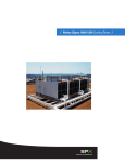
Three-Phase
Synchronous Motors
VEM group
VEM Sachsenwerk GmbH
VEM motors GmbH
VEM motors Thurm GmbH
Keulahütte GmbH
800 to 35,000 kW
VEM Products
Low-voltage machines
Three-phase asynchronous motors with squirrel-cage and slipring rotor up to 500 kW
Rollertable motors up to 160 kW
Explosion-protected motors up to 630 kW
Crane motors and marine motors
Special motors with brake, forced ventilator, encoder
Compact drives up to 22 kw
Energy-saving motors
Built-in motors
Tree-phase asynchronous generators
High-voltage machines
High-voltage asynchronous motors up to 28 MW
High-voltage synchronous motors up to 35 MW
High-voltage synchronous generators up to 45 MVA
Traction machines
Windpower generators up to 5.4 MW
Foundry products
Customer-made castings
Fittings, valves, hydrants
Your contact:
www.vem-group.com
we get things moving
SWD/04-007 E/0405 GD Printed in the Federal Republic of Germany. Changes reserved.
Sliding valves, flap valves
Page
Foreword
5
1.
Summary of supply
6
1.1
Synchronous motors with constant speed and
6
brushless excitation
1.2
Synchronous motors with speed control
7
2.
Type designation
8
3.
Norms and regulations
4.
Synchronous motors for constant-speed
9
10
applications
4.1
Voltage and frequency
4.2
Rated power output and heat generation
10
10
4.3
Direction of rotation
10
4.4
Overload capacity
10
4.5
Start-up
11
4.6
Modifications
11
5.
Converter-fed, variable-speed
12
synchronous motors
6.
Design description
13
6.1
Stator
13
6.2
Rotor
14
6.2.1
Rotor types
14
6.2.2
Description of the design and layout
14
6.3
Connecting boxes
15
6.4
Bearings
16
6.5
Cooling
18
6.6
Closed-loop control
18
6.6.1
Integration into E-systems
18
6.6.2.
Excitation cabinet
19
6.6.3.
Function of the excitation system
19
6.7.
Excitation
20
6.7.1
Description of the design and layout of
21
the excitation machine
Cover picture
Tree-phase synchronous motors
6.7.2
Start-up on the converter
21
6.7.3
Asynchronous low-load start-up
22
6.7.4
Asynchronous high-load start-up
22
6.7.5
Static excitation
23
7.
Explosion-proof motors
24
8.
Universal VEMoDUR insulation system
26
9.
Inspections
28
10.
Documentation
29
11.
Shipping, packaging, and installation
30
12.
General instructions
31
13.
Technical data
32
14.
Industry solutions
36
Foreword
VEM is one of the leading European suppliers of electrical machines for industrial applications. Our range of three-phase
high-voltage synchronous machines is primarily used in applications in the chemical and petrochemical industry, in steel
and rolling mill technology, in shipbuilding, in the cement industry and in the manufacturing industry. With this range we
can offer our customers a choice of high-performance drives
with a global pedigree. In their various design applications and
different protection classes and cooling types, the drives are
suitable for use in piston compressors, milling drives, pumps,
fans, blowers and transformers.
4
VEM can offer the right solution for any application with customer-specific and application-orientated machines. The are
characterised by reliability, ease of maintenance, modular design, high utilization and low noise emissions. A solid design
concept ensures the high level of adaptability required to be
able to incorporate individual customer requirements.
Comprehensive know-how in the factory and constant further
development in collaboration with institutes and universities
guarantee high-quality customer-specific solution.
The main features include:
• Long service life of windings with high, reliable switching frequency thanks to the use of the universal VEMoDUR insulating system, wich is backed with decades’ of experience.
• Inherent 20% thermal reserve built in tho the motors as
standard.
• Splinter-proof design of terminal boxes.
• Good weight-to-performance ratio offers improved installation conditions.
• Modular motor design ensures that spare capacity can be
built into the system both easily and cost-effectively.
• Minimal maintenance requirements, particularly on variants
with brushless excitation.
• Electromagnetic optimisation delivers high degree of utilization.
• Excitation devices for motors without brushes ands for
slipring motors supplied with automatic synchronisation and
asynchronous running protection.
All motors are designed in a customer-specific manner to fulfil
the special application criteria.
The catalogue contains general technical explanations. Individual requirements must be treated separately. The technical data for the basic series are also available on request from VEM.
We request that interested parties contact our factory sales department or VEM sales offices and VEM representatives.
Orders require our written confirmation.
Note:
We make every effort to constantly improve our products. For
this reason, versions, technical data and illustrations may be
changed. They are not binding until confirmed in writing by the
supplying factory.
5
1. Summary of supply
1.2 Synchronous motors with speed control
P/kW
1.1 Synchronous motors with constant speed and brushless excitation
Power in kW
20,000
18,000
Voltage:
Frequency:
16,000
14,000
Thermal class:
6 kV
50 Hz
Power factor: cos ϕ = 0.9
F / utilization B
3
Centre height/mm
2
1,120
12,500
1,000
10,000
8,000
104
9
8
6,000
4,000
900
7
2,000
6
1,000
800
5
800
4
600
710
560
3
500
400
1,500
1,000
750
600
500
4
6
8
10
12
630
2
Speed (min-1)
Number of Poles
Power in kW
35,500
30,000
Voltage: 10 kV
Frequency:
25,000
22,500
Thermal class:
50 Hz
Power factor: cos ϕ = 0.9
F / utilization B
20,000
103
9
8
7
6
18,000
Greater numbers of poles available on request.
14,000
5
4
11,200
9,000
3
5,000
Correlation:
Power, speed, centre height
1,120
800
710
102
2
3
4
5
6
7
8 9 103
6
2
n/min-1
560
1,500
1,000
750
600
500
4
6
8
10
12
Speed
(min-1)
Number of Poles
• Thermal class F / utilization B
• Rated voltage < 6 kV
• Air-to-water heat exchanger with forced ventilator
• xd“ = 11 – 16%
• Excitation: brushless/with brush
7
2. Type designation
3. Standards and regulations
The Sachsenwerk model designations consist of letters and numbers.
Letters
Numbers
Numbers/letters
Position
1-5
Position
6-9
Position
10-14
(variable, depending on the machine type)
The motors comply with the applicable DIN standards and
the DIN VDE regulations. For the basic designs, these include, in particular, DIN EN 60034 (VDE 0530) and IEC 60034
with its parts:
Part 1
DMM V X
Position
1
2
3
4
5
2 1 0 6
6
7
8
9
4 8 WD
10
11
12
13
Part 2
Part 4
14
Part 5
1
2
3
Type of current
E = Single-phase AC
D = Three-phase AC
M = Multiple-phase AC
Machine type
A AC current
K AC current
B AC current
S AC current
G AC current
R AC current
M AC current
T AC current
C AC current
U AC current
Part 7
Part 8
asynchronous generator
asynchronous squirrel cage rotor motor
asynchronous slip ring rotor motor with BAV
asynchronous slip ring rotor motor without BAV
synchronous generator with slip rings
synchronous generator without slip rings
synchronous motor with slip rings
synchronous motor without slip rings
commutator motor
single-housing converter
Cooling type, protection class
E Ventilated cooling / self-cooling without add-ons (IP00; IP10; IP20; IP21; IP22; IP23)
A Ventilated cooling / self-cooling with add-ons (IP23;
F Ventilated cooling / self-cooling pipe connection with internal fan (IP44; IP54; IP55)
L Draft ventilation / forced-air cooling supplemental ventilation unit or pipe connection
(IP00; IP10; IP20; IP21; IP22; IP23; IP24)
B Draft ventilation / forced-air cooling pipe connection (IP44; IP54; IP55)
R Circulation cooling / self-cooling air-to-air cooler (IP44; IP54; IP55)
K Circulation cooling / self-cooling air-to-water cooler (IP44; IP54; IP55)
S Circulation cooling / forced-air cooling with air-to-air cooler with additional ventilation unit (IP44; IP54; IP55)
M Circulation cooling / forced-air cooling with air-to-water cooler with additional ventilation unit (IP44; IP54; IP55)
N Circulation cooling / self cooling or forced-air cooling with gas as refrigerant (except air); all protection ratings
O Surface cooling / self-cooling with cooling holes (IP44; IP54; IP55)
C Surface cooling / self-cooling with cooling fins (IP44; IP54; IP55)
P Surface cooling / self-cooling without fan (IP44; IP54; IP55)
W Surface cooling / forced-air cooling with water cooling jacket (IP54)
V Surface cooling / forced-air cooling with additional ventilation unit (IP54)
4 and 5
Design type (encoded)
Bearings, deviating voltage and frequency, Explosion protection, construction, high-load start, etc.
6 and 7
Shaft centre height (encoded)
8 and 9
Stamping pack length (encoded)
10 and 11
Number of poles/speed
12 to 14
Additional letter for rework stage and special conditions
Letter codes for special winding designs
8
Part 6
Part 9
Part 14
Part 15
Part 16
Part 18
Dimensioning and operational behaviour
DIN EN 60034-1 (VDE 0530-1) - IEC 60034-1
Methods for determining the loss of efficiency ...
DIN EN 60034-2 (VDE 0530-2) - IEC 60034-2
Methods for determining key synchronous machine
variables from tests
DIN EN 60034-4, VDE 0530-4, IEC 60034-4
Classification of protection classes
DIN EN 60034-5 (VDE 0530-5) - IEC 60034-5
Classification of cooling methods
DIN EN 60034-6 (VDE 0530-6) - IEC 60034-6
Classification of design types
DIN EN 60034-7 (VDE 0530-7) - IEC 60034-7
Connection designations and direction of rotation
DIN EN 60034-8 (VDE 0530-8) - IEC 60034-8
Noise limits
DIN EN 60034-9 (VDE 0530-9) - IEC 60034-9
Mechanical vibrations ...
DIN EN 60034-14 (VDE 0530-14) - IEC 60034-14
Surge voltage ratings ...
DIN EN 60034-15 (VDE 0530-15) - IEC 60034-15
Excitation systems for synchronous machines
DIN EN 60034-16… (VDE 0530-16) – IEC 60034-16
Functional evaluation of insulation systems ...
DIN EN 60034-18-... (VDE 0530-18-...)
- IEC 60034-18-... several parts
as well as
DIN ISO 10816-... Evaluation of the vibrations of machines
- ISO 10816...
through measurements of non-rotating
parts... (several parts)
DIN ISO 8821
Mechanical vibrations, agreement on the
- ISO 8821
feather key type when balancing shafts
and connecting parts
DIN ISO 1940-... Requirements for the balancing quality of
- ISO 1940...
rigid rotors ... (several parts)
DIN ISO 7919-… Measurement and evaluation of
- ISO 7919
mechanical vibrations
In the case of explosion-proof machines, the fundamental
safety requirements are ensured by designs that meet the
standards:
DIN
DIN
DIN
DIN
DIN
DIN
DIN
DIN
EN
EN
EN
EN
EN
EN
EN
EN
50014 (VDE 0170/0171 part
60079-0 – IEC 60079-0
50016 (VDE 0170/0171 part
60079-2 – IEC 60079-2
50019 (VDE 0170/0171 part
60079-7 – IEC 60079-7
50021 (VDE 0170/0171 part
60079-15 – IEC 60079-15
1),
3),
6),
16),
On request, the products can be supplied in accordance with
other standards, such as IEC standards currently being ratified,
as well as in accordance with special industry regulations, such
as ZLM (additional supply agreements for high-voltage electrical motors in power plants), regulations from all of the major ship classification associations or the Shell specification.
9
4. Synchronous motors for constant-sped applications
4.1 Voltage and frequency
In the basic design, the motors are dimensioned for a rated
voltage of 6 kV and a rated frequency of 50 Hz, with a power
factor of cos ϕ = (0.9 ever-excited).
Voltage and frequency fluctuations during operation are possible in agreement with the stipulations in DIN EN 60034-1
(VDE 0530 part 1), IEC 60034.
Motors for voltage ranges ) 3.3 kV have higher, motors for
voltage ranges > 6.6 kV lower rated outputs with the same
construction models.
4.2 Rated power output and heat generation
The rated outputs stated in the summary of supply hold for
continuous operation (S1) at rated frequency, rated voltage,
installation altitude ) 1,000 m above sea level and a maximum
cooling air entry temperature of 40°C or cooling water entry
temperature of 27°C. The maximum winding temperatures
correspond to thermal class B in accordance with DIN IEC
60085 (VDE 0301 part 1), IEC 60095, measured using the resistance method.
10
Motors can be supplied with a maximum permissible temperature rise in accordance with thermal class F.
4.3 Direction of rotation
As a general rule, the synchronouse motors must only be operated in the agreed direction of rotation. Special fans can
be used in cases requiring bi-directional operation. Fans for
bi-directional operation cause greater frictional losses and
therefore achieve a lower efficiency.
4.4 Overload capacity
The synchronous breakdown torque is 1.5 / 1.35 times the
rated torque for salient-pole motors and smooth-core rotor
motors respectively.
Depending on the drive task in hand, these values can be
modified.
4.5 Start-up
The motors are designed for a direct start-up. In principle, reduced start-up current can be achieved by:
• reducing the stator voltage with an autotransformer or reactance coil.
• frequency start-up
Pole design
solid
laminated with start-up cage
Load moment
fan
piston compressor
The parameters of the machine need to be quoted in all cases
so that the start-up conditions can be assessed,
including:
• load moment curve (from idling to rated speed)
• mass moment of inertia
• maximum permitted mains voltage breakthrough during the
start-up phase
• number of start-ups in direct sequence
4.6. Modifications
• Rated voltage up to 13.8 kV
• 60 Hz or other rated frequency
• Power factor control
• Large-scale and special motors for rated torques of up to
2,000 kNm
• Air-to-air hear exchanger
• Start-up with additional resistor in the rotor circuit for difficult start-ups
• Explosion-proof version
MA /MN = f(n/nN)
Schematic diagrams of the start-up torque depending on
pole design.
11
5. Converter-fed, variable-speed synchronous motors
6. Design description
Synchronous motors with variable speed control are used in
a wide variety of industrial applications. Synchronous motors
with a rated power output in excess of 1 MW have established
themselves ahead of DC drives particularly in rolling mills, on
ships and in the chemical industry.
6.1 Stator
The stator housing is a welded construction comprising end
walls and intermediate walls with support ribs, bars and sheet
casing. It stands on base plates on the foundations.
The stamping pack consists of insulated dynamo sheet round
plates or overlapped layered dynamo sheet segments, and it
is axially tensioned over end plates with press pins and weldedon bars. On machines with a diameter of up to 4,000 mm, the
stamping pack is wound with whole pulled coils, fully impregnated according to the VPI process and shrink-fitted into the
stator housing.
On larger machines, the insulated dynamo sheet segments are
overlapped and layered on guide bars in the housing, tensioned
and then wound with vacuum-pressure impregnated transposed conductor rods or pulled coils which are premanufactured according to the resin-rich process.
The three-phase stator winding lies in the open slots of the
stamping pack. Depending on the rated power output, it is implemented as a double-layer whole pulled coil or double-layer
transposed conductor winding.
With the whole pulled coil, the conductive material is made of
flat copper wire which is insulated with mica foil. For the conductors of the transposed conductor winding twisted in the slot
part, lacquer-fibreglass-insulated flat copper wires are used
and fastened as a wire bundle with mica-prepreg.
The main insulation of the coils or rods consists of mica-fibreglass tape. To avoid corona discharges, a low impedance mica
protective cover is installed in the slot part and a high impedance protective cover is installed in the slot exit.
The fully insulated conductor packages are fixed in the slots
using slot connectors.
The winding heads are safely supported against the mechanical loads arising during switching operations due to binding,
spacer pieces or retaining rings.
The switch connections are hard-soldered at the whole pulled
coil winding; in the case of transposed conductor windings,
the rod connections are made through TIG-inert gas shielded
arc welding.
• dynamic and quasi-stationary overload torques on rolling
mill motors
• adaptation of the electromagnetic parameters to the special
requirements of speed-controlled drives
• additional insulation of the bearings on the D end and spindle
grounding brush depending on the type of converter used.
The advantages of synchronous machines include:
• greater power and speeds can be achieved with the engine
• robust design which is adapted to the drive tasks
• low-maintenance operation
• high degree of efficiency
• speed setting can be used with a wide field suppression
range
• commutation reactive power (load-controlled inverter) can
be taken over
Depending on the system components and drive-specific
requirements, the motors can be implemented in the form of
smooth core rotor motors or salient-pole motors, or
with/without brushes.
The operation of the motors on frequency converters results
among other things in a higher noise level than with sinusoidal
mains power networks. In the case of converters, the increase
in the acoustic pressure level depends on:
Design concept
In contrast to conventional synchronous machines, the design
of converter-fed machines also takes the following aspects
into account:
• dimensioning of the stator winding insulation for operation
on a direct converter or indirect converter and the relevant
rated voltage
• converter type
Synchronous motor for frequency converter operation, rolling
mill drive, type DMMYZ 8044-6Y
Stator for rolling mill drive, type DMMYZ 2246-6Y
12
• pulse frequency
• pulse pattern
• output filter
In the case of converter-fed machines, the converter type must
be stated in the inquiry.
13
6.4 Bearings
The type of bearings used depends on the requirements resulting from the mechanical loads and the machine which is
to be driven. As a general rule, an attempt is made to ensure
maximum operational safety and reliability and maximum service life.
Rolling bearings
The motors are equipped with DIN-standard rolling bearings.
A deep groove ball bearing is used as a guide bearing on the
D end. At absorbs the radial and (low) axial loads. A cylinder
roller bearing is used as a floating bearing on the ND end.
Under increased mechanical loads and higher speeds, the
deep groove ball bearing on the D end is reinforced with a
cylinder roller bearing. At lower speeds, a deep groove ball
bearing is used at the ND end instead of the cylinder roller
bearing as a floating bearing in an axial position. In applications where the synchronous motor is designed to absorb
additional axial loads, a special bearing with pre-loaded angular contact ball bearings is used.
The axial loads and radial loads should be quoted in the request / specification.
All rolling bearings are lubricated with lithium-base-saponified
grease of consistency class 3.
The bearing modules are equipped with an automatic grease
quantity control system. This ensures perfect lubrication levels after re-greasing.
In accordance with the specifications in the motor documentation, the bearings must be regularly re-greased with the indicated type and quantity of grease in order to make sure that
the bearings achieve their nominal service life. This is done
using M10x1 flat grease nipples in accordance with DIN 3404.
The bearings for smaller synchronous motors are equipped
with a storage receptacle for the old grease. Provided the
proper re-greasing schedule is followed, this receptacle is
large enough for the calculated service life of the bearings.
Bearings for larger motors have storage receptacles for old
grease which can be emptied from outside.
The bearings are sealed to the inside of the motor and to the
outside with gap seals. They are maintenance-free and protect
against penetration of dust and water. The bearing heads on
the ND end are insulated against the motor housing to prevent
bearing currents.
The rolling bearings are monitored via Pt100 temperature
measurements. Versions can be implemented with vibration
monitoring.
Sliding bearings
Depending on the design of the machine, the sliding bearings
can be designed as flange bearings or as pedestal bearings,
or they can be centred on the end plate.
The types of bearing used include bearings with a split housing, split bearing shells and split lubricating rings and sealing
rings. This enables bearings to be serviced and sealing rings
to be replaced without the need for disassembly of adjacent
motor component groups or couplings.
The protection class of the bearings in their basic design is
IP 44. Higher protection classes (IP54 or IP55) can be achieved
by using additional seals/gaskets.
The bearing shell of the sliding bearing on the ND side is insulated to prevent bearing currents.
The sliding bearings are usually designed as floating bearings,
i.e. the motor rotor is guided via a coupling with limited axial
clearance by the supporting bearing of the machine. It is also
possible to use a locating bearing if no axial forces are directed
from the machine or coupling onto the motor spindle. Special
bearing shells are used for applications where axial forces
need to be absorbed.
The sliding bearings are preferably cooled via heat dissipation
through the surface of the bearing housing. If the operating
conditions do not allow this, then the bearings can also be
cooled with rinsing oil or via an integrated water cooler. At low
speeds or in applications with greater rotor masses, a hydrostatic rotor boost is used.
Lubrication is provided by means of lubricating oils with a viscosity class which is governed by the operational data of the
sliding bearing. Use of other oils must be agreed with VEM.
Appropriate oil supply units are available from VEM for the use
of rinsing oil to cool the bearings.
The bearing shells on the ND end are insulated to prevent bearing currents.
Monitoring is preferably implemented via Pt100 temperature
measurements. A version with vibration dampers is available.
For connection to a rinsing oil system, we can supply choke
screws (which are used to control the flow rate of the oil) and
a flow rate display unit or monitor.
Rolling bearings
16
Sliding bearings
17
6.5 Cooling
The machine is air-cooled inside. The air is either pumped
axially or radially through the rotor and stator via fan wheels
which are attached to the spindle (self-cooling) or via additional add-on fans with a motor (forced ventilator). In the
process, the air absorbs waste heat from the stamping pack
and the windings.
The choice of cooling method depends on the overall plant
project and is primarily governed by the required protection
rating and the available media. Standard cooling methods include:
Open cooling circuit (up to protection rating IP23)
Ambient air is used as cooling air. Once it has cooled the machine it is discharged back into the atmosphere.
Appropriate shutters are used to ensure that the required protection rating is attained.
Closed cooling circuit with connected heat exchanger
(protection rating IP44 and above)
The cooling air inside the motor is pumped to a closed circuit
(primary circuit), where it discharges its heat via a heat exchanger to a cooling medium (secondary circuit). Air-to-water
or air-to-air heat exchangers are used.
In the case of air-to-water heat exchangers, the pipe material
used is governed by the quality of the cooling water. Doublepipe versions and versions with water leakage warning systems
and flow monitors are also available.
In the case of air-to-air heat exchangers, the outside air is
Open cooling circuit
18
pumped through the heat exchanger by means of additional
forced ventilators.
6.6 Closed-loop control
6.6.1 Integration into E-systems
When the synchronous motor is operated directly off the mains
supply, the excitation unit represents the control link between
the E-system and the motor. This applies to both brushless
and static excitation systems which have analogue or digital
excitation control. Depending on the size of the motor and
the configuration of the E-system, a greater or lesser number
of control functions are performed or assessed by the excitation unit.
Key features of the synchronous machine are achieved through
open and closed-loop control of the excitation, as a result of
which the scope of functions of the excitation unit may vary
to a great extent depending on the specific requirements from
the plant project.
Excitation control functions are used among other things to
influence the start-up behaviour, the stability during non-stationary processes and the re-synchronisation behaviour.
The open-loop excitation control enables the following functions to be implemented within the program:
•
•
•
•
•
Anti-blocking protection
Start-up monitoring
(Deliberate) synchronisation
Crank angle control
Triggering of protection systems
Closed cooling circuit (air-to-air)
•
•
•
•
•
•
•
•
Asynchronous running protection with re-synchronisation
Setpoint adjustment
Controller status control (Auto/Manual…)
Warning and error message displays
On-site controls via operator panel
Rotating diode monitoring
Controller monitoring
Rotor ground fault monitoring
The exchange of signals for plant control purposes takes
place digitally via the mutual provision of potential-free relay
contacts or relay coils. The exchange of analogue signals
takes place via potential-free coupling blocks with standardized current or voltage outputs. Other methods for exchanging
signals, such as serial bus links, can be modified to suit specific requirements.
6.6.2 Excitation cabinet
The excitation unit is usually laid out as a switching cabinet,
on static installations also as a combination of several switching cabinets. On simple devices for low-power applications,
other designs can also be supplied, including motor attachment, wall attachment or assembly plate attachment. The cabinet properties are adapted according to the specific requirements of any given application.
The steel control cabinet contains the entire open and closedloop excitation control systems. An inspection window on the
front door is available on request to provide a view of the important measuring instruments and displays. A bottom plate
with PG screw fastenings can also be supplied for the cabinet,
which is otherwise open at the bottom.
Switching devices and, if applicable, the power section are
located on the assembly plate in the rear of the cabinet.
The open and closed-loop controllers are mounted on a pivoting frame. The pivoting frame is omitted on smaller units. In
this case the open and closed-loop controllers are also housed
on the assembly plate.
6.6.3 Function of the excitation system
In principle, the closed-loop control of a synchronous motor
via its excitation takes place under the aspects of drive stability and the specific requirements of the E-system or mains
supply. Although these aspects are not mutually exclusive, the
configuration of the overall system should be carefully balanced
in both their favour.
Closed-loop reactive power control is generally utilised, which
operates with a subordinate (auxiliary) excitation current control on brushless systems, as this provides good settling
times. As an alternative, cosj control can also be used as a
derived form of reactive power control.
Measured values which are only indirectly connected to the
synchronous motor can also be used as the actual values
for the controller, as a result of which the behaviour of the
entire network island is influenced. Similar effects can also
Closed cooling circuit (air-to-water)
19
be achieved variable setpoint specifications which are generated in a higher level control.
A range of limiting controllers are used primarily to prevent a
loss of stability of the motor.
The limitation of the rotor displacement angle is based on a
system of detecting the angle via inductive sensors in the
motor.
The excitation current control serves for servicing and manual operation purposes, as well as for simple operation from a
higher level control. In the process, the internal setpoint is
adjusted via HIGH/LOW signals.
Depending on the project requirements, more or less complex analogue or digital devices are used.
Basic functions:
• Reactive power control
• Digital setpoints
• Manual operation
• Excitation current control
• Limitation of excitation current
• Limitation of over and under-excitation
20
Possible upgrades:
• Remote setpoint processing
• External actual value processing
• Limitation of rotor displacement angle
• Stator current limitation
• Reactive power limitation
Depending on the required mode of operation for the motor,
the excitation machine is laid out as either
• a three-phase rotating armature excitation machine with
DC supply on the stator side, or
• a three-phase excitation machine with three-phase current
supply on the stator side.
Other functions required in addition to the above should be
discussed with VEM.
The rotor of the excitation machine supplies the excitation
power to the excitation winding of the motor via rotating rectifier modules which are connected in a three-phase bridge
connection.
6.7 Excitation
The synchronous motors are supplied as brushless versions as
standard.
Alternatively, excitation via a slip ring arrangement is also available.
The brushless version is maintenance-free and can also be
used when the motor is operated in an atmosphere with an
increased risk of explosion.
6.7.1 Description of the design and layout of the excitation machine
The excitation machine is a three-phase external pole generator, the rotor of which is mounted together with the diode
bridge and protective circuitry on a hub. This unit can be pulled
off the spindle with minimal installation effort in terms of the
excitation stator.
The rotating brushless excitation unit (excitation machine, rectifier, start-up thyristor, protective circuitry and, if applicable,
start-up resistor) can be arranged both inside and outside the
machine.
The stator of the excitation machine is supported by the end
plate on the ND side, or it is supported by a supporting star
on larger machines. The stator consists of a stamping pack
made of insulated dynamo sheet round plates with stampedout poles. These poles carry a DC winding. If the synchronous
machine is intended to be operated with a frequency-controlled
start-up, then the excitation stator is laid out with a three-phase
winding.
Excitation cabinet
Salient-pole rotor with excitation machine
The rotor of the excitation machine is located on the rotor,
where it is pulled on over a bush. The rotor has a stamping
pack made of insulated dynamo sheet round plates with a
three-stranded three-phase winding. A 6-pulse bridge circuit
rotates together with the rotor to rectify the voltage induced
in the excitation rotor. The output of the bridge is branched
off to the excitation coil of the rotor.
6.7.2 Start-up on the converter
The power supply to the stator winding of the synchronous
motor is provided from the mains supply via a converter. The
latter features a complex open and closed-loop controller which
regulates the required output voltage of the converter according
to the current operating point of the motor.
In addition, the optimum excitation current for the excitation
machine is also usually provided by the converter unit via a
three-phase power controller. The excitation machine acts as
a transformer during start-up. With increasing speed, this mode
of operation is superseded by generator operation.
In order to supply the voltage to the motor excitation winding,
there is a three-phase diode bridge on the output of the rotor
winding which is terminated on the DC side with a varistor or
RC circuit to reduce transient voltage peaks.
Rotor and diode bridge of the excitation machine
21
Depending on the application, the converter is only used during start-up. In the process, the power rectifier is bridged
once mains synchronism is attained, as a result of which the
motor is run directly off the mains. This means that the converter is only called upon during start-up, with the corresponding implications for dimensioning. Closed-loop excitation control is also provided by the converter complex during synchronous mains operation.
6.7.3 Asynchronous low-load start-up
In the event of operation without supply from a converter and
with a relatively low load moment, the brushless synchronous
motor can also start up asynchronously, provided provisions
are in place in the rotor circuit for the AC start-up current in
the excitation coil.
The positive half-wave of the AC start-up current flows through
the rectifier diode bridge which is already in place. The negative half-wave flows anti-parallel through voltage-controlled
thyristors to a diode branch of the rectifier bridge.
The voltage-controlled triggering of the thyristors is achieved
by virtue of the current-forcing character of the AC start-up
current.
The thyristors are reliably turned off during operation by being
connected to the AC voltage of the excitation machine by
means of voltage zero.
6.7.4 Asynchronous high-load start-up
To start up the synchronous motor without a supply from a
converter against a relatively high load moment, the excitation
coil must be terminated with an optimised start-up ipedance.
This has the effect that the asynchronous moment of the moment is increased, pull-up torques are prevented and tendencies to vibrate are significantly reduced. If the start-up impedance was to remain connected after synchronization has taken place, additional losses would be encountered. Suitable circuit connections are implemented to prevent permanent
connection of the start-up impedance even with brushless
excitation. At the same time, this method also achieves deliberate synchronisation. This synchronisation generates a very
good synchronising moment and also enables the so-called
crank angle control.
Depending on polarity, the AC start-up current flows either
through a diode or a voltage-controlled thyristor via the start-up
impedance in the rotor circuit, whereby the series-thyristor
remains untriggered.
When the minimum slip is reached, the rotor displacement
angle is sensed in order to connect the excitation voltage to
the excitation coil by triggering the series thyristor. In the event
of an overload, the sufficiently high slip component of the excitation current switches off the series thyristor, allowing the
motor to be re-synchronised once the minimum slip is reached
again.
6.7.5 Static excitation
As an alternative to the brushless excitation method, a static
excitation device can also be used.
The advantages of this method are: direct access to the excitation circuit, omission of the auxiliary excitation time constant
and comparatively highly dynamic response of the control
system.
The necessity of slip rings for transferral of the excitation current, the higher auxiliary power requirements and the additional
expense of the excitation current actuator, which is balanced
by the omission of the excitation machine, all need to be taken
into account.
There are no differences between the brushless and static
excitation systems in terms of open and closed-loop control
functions. The choice of which system is used depends primarily upon the varied requirements of the site where it is to
be used, although the brushless excitation system is generally
the standard choice.
Slip ring arrangement
The brush bridge consists of a brush carrier to which insulated brush pins with brush holders are attached. The brush
carrier is supported by the end plate on the ND side, or it is
supported by a supporting star on larger machines.
A slip ring body is shrink-fitted to the spindle, and this in turn
takes the slip rings which are made of stainless steel. There
are branch-off conductors made of round copper on the slip
rings which lead to the excitation coils of the rotor.
4
1
2
3
4
exciter
mains
converter
motor
Schematic diagram showing a rotor with connected converter
22
1
2
3
4
exciter-regulator
exciter and rectifier bridge
mains
motor
Rotor circuit diagram - asynchronous low-load start-up
1
2
3
4
5
exciter-regulator
exciter and rectifier bridge
mains
motor
firing
Schematic circuit diagram showing the rotor during
a heavy-load start-up
23
7. Explosion-proof motors
Special regulations and directives apply to the setting-up of
motors in explosion-hazardous areas in which dangerous
concentrations of explosive atmospheres can build up. The
areas are divided into zones (EN 60079-10 (VDE 0165 part
101), IEC 60079-10) and the production tools, i.e. the electric
machines as well, are divided into device categories or ignition protection types. All European manufacturers must comply with the ATEX guidelines, which became legally binding as
of 1 July 2003.
24
Depending on the conditions at the location of use, Sachsenwerk motors are delivered in accordance with DIN EN 50014
(VDE 0170/0171 part 1), DIN EN 60079-0 – IEC 60079-0 with
the following types of ignition protection:
• increased safety “e” (in accordance with DIN EN 50019
(VDE 0170/0171 part 6) and IEC 60079-7 – IEC 60079-7) –
on request
• pressurisation „p“ (in accordance with DIN EN 50016 (VDE
0170/0171 part 3), DIN EN 60079-2 – IEC 60079-2)
• sparkless in normal operation „n“ (in accordance with DIN
EN 50021 (VDE 0170/0171 part 16), DIN EN 60079-15 –
IEC 60079-15)
The fundamental safety requirements for explosion-proof motors in ignition protection type „e“ as per IEC 60079-7 are increased considerably compared to the previous design according to DIN EN 50019 so that, in the stage of contract preparation, a risk evaluation of possible ignition dangers should be
conducted, and measures to minimise risk should be adopted
if applicable.
For high-voltage machines with rated voltage UN > 6 kV, a system test for the complete insulation system under an ignitable
atmosphere remains necessary. The corresponding certificate of the PTB-Braunschweig as a recognized test authority is available for a Sachsenwerk insulation system VEMoDUR-VPI-155.
Scavenging air control system (EEx p)
Synchronous motor, 3.5 MW extruder drive (EEx p)
25
8. Universal VEMoDUR insulation system
The operating reliability of electrical machines is determined
to a large extent by the quality of their winding insulation. The
insulation technology at Sachsenwerk has always been characterised by technical solutions which, in terms of their quality
parameters, meet applicable international standards and thus
ensure products which are highly reliable and offer their operators a long service life.
The VPI technique (vacuum pressure impregnation) is used
for high-voltage machines. The associated insulation system
VEMoDUR-VPI-155 was developed at Sachsenwerk and is
registered as a trademark . The designation “VEM” stands for
“Vereinigter Elektromaschinenbau” and “DUR” for the duroplastic behaviour of the insulations with synthetic adhesives
that are used.
This system contains the following listed main components
for the stator windings:
Winding insulation
Main insulation
(groove and core chuck)
Impregnating material
⇒ mica foil bands
⇒ mica-fibreglass bands
(contains accelerator, low adhesive)
⇒ epoxy resin
The components are optimally matched to each other. The
insulation class F has been confirmed through many years of
operating experience and functional evaluation as per DIN
EN 60034-18-31 (VDE 0530 part 18-31) - IEC 60034-18-31.
To guarantee the quality of the insulation system, all compo-
nents are subjected to a receipt inspection in accordance with
DIN EN ISO 9001 – ISO 9001.
During the impregnation process, the insulation is subjected
to a constant control system, whereby characteristics such as:
• viscosity of the resin
• impregnation and curing temperature
• pressure maintaining times
• under- and overpressure
• pressure impregnation
• are checked and documented.
The insulation is cured in rotation.
Vacuum-pressure impregnation guarantees a high mechanical
strength (core chuck rigidity) and outstanding electrical
strength. This holds especially for the distance sparkover voltages. Rated surge voltages in accordance with DIN EN
60034-15 (VDE 0530 part 15) – IEC 60034-15 are guaranteed
for all machines with a great degree of reliability (see table
extract).
Insulation level of rotating electrical machines with stator
pulled coil windings in accordance with DIN EN 60034-15
(VDE 0530 part 15) – IEC 60024-15 (extract)
The insulation system is highly resistant to climate influences,
Rated voltage
UN in kV
The insulation systems is highly resisitant to climate influences,
i.e. the winding is not sensitive to humid or aggressive atmospheres.
The VPI insulation system represents the standard design.
The technically equivalent resin-rich insulating system is used
on very large machines. With this system, resin-rich mica fibreglass insulating bands are bound onto the main insulation and
the winding head insulation and then hardened in the slot
part under pressure and heat.
Within the framework of internal quality inspection in accordance with DIN VDE, electrical interim and final checks of the
insulation strength are performed together with (on customer
request) surge voltage and partial discharge level tests. This
ensures a quality that meets market demands and competitive requirements.
The VEMoDUR insulation system is also suitable for machines
with "increased safety" ignition protection type EExe in accordance with DIN EN 50019 (VDE 0170/0171 part 6) as well
as Exe as per IEC 60079-7 – IEC 60079-7.
Rated surge
Mains frequency
voltage
testing voltage
(peak value) in kV (effective value) in kV
Shaft 1.2/50
(2UN + 1 kV)
(4UN + 5 kV)
6
6.6
29
31
13
14.2
10
11
45
49
21
23
13.8
15
60
65
28.6
31
VEM can also supply special designs with increased rated
surge voltages on customer request.
Example:
UN = 11 kV
Main insulation:
80 kV
Winding insulation: 60 kV
26
27
9. Inspections
An effective quality assurance and management system guarantees the optimal value and quality of the motors. Every motor is subject to an internal individual inspection. The results
of the inspections are documented in an inspection log. This
is part of the delivery documentation.
Individual inspections
• Visual inspection (identification, completeness, condition of
construction, quality of assembly, brush type and dimensions etc.)
• Air gap measurements (if permitted by the construction)
• Insulation resistance of the windings, temperature probes,
anti-condensation heaters, bearings (inspection performed
during assembly)
• Ohmic resistances of the windings, temperature probes,
anti-condensation heaters
• Measurement of the magnet wheel impedance
• Setting of the magnetic centre for sliding bearings
• Idling characteristic curve for determining magnetic and
frictional losses, calculation check of efficiency, if required
• Check of direction of rotation
• Inspection of the voltage geometry
• Winding checks
• Vibration severity measurement
• Short-circuit characteristic curve and loss measurement
(generator method)
• Determination of the SPM level (if corresponding feature is
available)
• Current overload test
• Winding check (high voltage test)
• Functional capability of the accessories
Type inspections
If the customer wishes, additional inspections can be performed within the scope of the type inspection. The addition-
28
10. Documentation
al costs will be charged to the customer. In this case, the following inspections are conducted in addition to the individual
inspection:
• Overspeed test
• Recording of the idling characteristic curve and loss measurement
• Noise measurement at idle
• Wave voltage measurement on machines with insulated
bearings (if permitted by the construction)
• Degree of distortion of the voltage curve
• Measurement of the THF factor
• Reactances and time constants – determination of the
residual voltage
• Short-circuit characteristic curve and loss measurement
(motor method)
• Surge short-circuit check
• Load characteristic
• Control characteristic
• Determination of the nominal excitation current
• Determination of the degree of efficiency
• Air quantity measurements, pressure losses
• Thermal test with rated data or substitute tests
• Anti-condensation heating
• Thermal time constants, load limit determination
• Cooling time constants
• Runout measurement, determination of the mass moment
of inertia
• Runup measurement, determination of the start-up characteristics
• Determination of the key variables of the synchronous machine
• Measurement of the SPM level
• Operating characteristic curves η = f(Pel), cos ϕ = f(Pel),
Pmech = f(Pel), s= f(Pel), l=f(Pel)
Unless agreed otherwise, the „Operation and Service Manual“
documentation contains the following documents:
• Safety instructions
• EC manufacturer’s declaration
• Description / technical data
• Dimensional drawing of motor
• Dimensional drawing of cable connections
• Connection plans for temperature monitoring,
anti-condensation heaters
• Installation / assembly
• Commissioning
• Operation
• Maintenance
• Servicing
• Replacement parts list
• Test certificate / log book
• Supplemental operation manuals (options, third-party suppliers)
Any additional documentation beyond this scope must be
agreed by contract.
The documentation is provided in two copies when the product
is delivered. It is available in all EU languages.
VEM charges for costs of additional copies, additional documentation, and translation into other languages.
29
11. Shipping, packaging, installation
12. General instructions
The type of packaging is determined at the time of contract
according to the transportation and storage conditions specified in the order and takes into account the design and construction of the machines. VEM can offer all types of special
packaging and provide shipping and installation of motors to
any destination worldwide.
If not expressly requested and offered otherwise, the machine
is designed as follows:
The machines are shipped either fully assembled or disassembled depending on the size and contractual agreements.
VEM recommends the installation and commissioning service
of our specialist personnel.
30
If the customer prefers to perform the installation and commissioning themselves or have this work done by a third party,
then the performance of this work must be verified in section
9 (test certificates, logbook) of the VEM Operation and Service
Manual, or by other means. Failure to comply with this requirement will absolve VEM from any liability or warranty obligations.
The VEM Operation and Service Manual is delivered with the
machine.
If contractually agreed, the documentation can also be sent
separately to the buyer or operator.
• It is built with the insulation system VEMoDUR.
• It is painted in accordance with Sachsenwerk Standard
SW-N 170-004, which is based on DIN EN ISO 12944 ...
– ISO 12944... and applicable standards.
• The machine’s direction of rotation is right, when looking at
the drive (D) end. The connecting box is positioned on the
right.
• The cooler is located on the machine and the water connection is on the left when looking at the drive (D) end.
• Water cooler up to the connecting flange without monitoring
on the water side.
• Without cable stuffing socket.
• PT 100 for winding and storage in 2-wire switch without
trigger device, from terminal box connection in 2-, 3- and
4-wire design.
• Mechanical vibrations correspond to the limits specified in
EN 60034-14 and are proved in the test lab.
• Vibration monitoring is performed without an evaluation
device.
31
13. Technical data
Power range
Brushless high-voltage synchronous motors 6 kV
50Hz · cos ϕ = 0,9ü · Number of poles 4-12 · Thermal class F (utilization B)
Typ
Centre height
Power range
Brushless high-voltage synchronous motors 10 kV
50Hz · cos ϕ = 0,9ü · Number of poles 4-12 · Thermal class F (utilization B)
1500 min-1
Power output
1000 min-1
750 min-1
600 min-1
500 min-1
Typ
450
800
560
400
-
-
450
1000
710
500
-
-
5018
500
1250
900
630
500
400
5023
500
1600
1120
800
630
500
5621
560
2000
1400
1000
800
5627
560
2500
1800
1250
1000
6321
630
2800
2000
1400
6324
630
3150
2250
1600
6327
630
3550
2500
6329
630
4000
7125
710
7127
710
7130
Centre height
Power output
(mm)
1500 min-1
1000 min-1
750 min-1
600 min-1
500 min-1
-
-
-
-
-
-
-
-
-
-
-
-
-
-
5018
500
1120
800
560
-
-
5023
500
1400
1000
700
-
-
630
5621
560
1800
1250
900
710
560
800
5627
560
2250
1600
1120
900
710
1120
900
6321
630
2500
1800
1250
1000
800
1250
1000
6324
630
2800
2000
1400
1120
900
1800
1400
1120
6327
630
3150
2250
1600
1250
1000
2800
2000
1600
1250
6329
630
3550
2500
1800
1400
1120
4500
3150
2250
1800
1400
7125
710
4000
2800
2000
1600
1250
5000
3550
2500
2000
1600
7127
710
4500
3150
2250
1800
1400
710
5600
4000
2800
2250
1800
7130
710
5000
3550
2500
2000
1600
7133
710
6300
4500
3150
2500
2000
7133
710
5600
4000
2800
2250
1800
8030
800
7100
5000
3550
2800
2250
8030
800
6300
4500
3150
2500
2000
8033
800
8000
5600
4000
3150
2500
8033
800
7100
5000
3550
2800
2250
8036
800
9000
6300
4500
3550
2800
8036
800
8000
5600
4000
3150
2500
8040
800
10000
7100
5000
4000
3150
8040
800
9000
6300
4500
3550
2800
9033
900
11200
8000
5600
4500
3550
9033
900
10000
7100
5000
4000
3150
9036
900
12500
9000
6300
5000
4000
9036
900
11200
8000
5600
4500
3550
9040
900
14000
10000
7100
5600
4500
9040
900
12500
9000
6300
5000
4000
9045
900
16000
11200
8000
6300
5000
9045
900
14000
10000
7100
5600
4500
1038
1000
18000
12500
9000
7100
5600
1038
1000
16000
11200
8000
6300
5000
1042
1000
20000
14000
10000
8000
6300
1042
1000
18000
12500
9000
7100
5600
1047
1000
-
16000
11200
9000
7100
1047
1000
20000
14000
10000
8000
6300
1053
1000
-
18000
12500
10000
8000
1053
1000
22500
16000
11200
9000
7100
1148
1120
-
20000
14000
11200
9000
1148
1120
25000
18000
12500
10000
8000
1153
1120
-
-
16000
12500
10000
1153
1120
28000
20000
14000
11200
9000
1158
1120
-
-
-
-
-
1158
1120
31500
22500
-
-
-
1164
1120
-
-
-
-
-
1164
1120
35500
-
-
-
-
DT…
(mm)
4516
4519
32
DT…
33
14. Industry solutions
Excerpt
Ordering party
Object /
Driven equipment
Machine type
Qty.
Power output
kW
Rated voltage
kV
2004
DMS ZI LILLE SECLIN
Quingdao / China
Rolling mill drive
DMMYZ 8044-6Y
7
4,000
3.0
2003
Alstom
Rasselstein /Deutschland
Rolling mill drive
DMMYZ 9040-4Y
1
4,000
2.0
2003
Alstom
TKS Bruckhausen / Deutschland
Rolling mill drive
DMMYZ 2246-6Y
1
5,000
2.0
2003
Linde AG
Kollsnes / Norwegen
Turbocharger compressor drive
DTKFU 1044-4WS
EExp IIA T3
1
18,500
11.0
2003
Lungi
LDPE Marun / Iran
Piston compressor drive
DTKVY 4931-30WS
EExp II T3
1
22,400
11.0
2002
Siemens AG
CISA RCM / Brasilien
Coiler drive
DMMYZ 8040-6
2
2,719
3.3
2002
Siemens AG
CISA RCM / Brasilien
Stand drive
DMMYZ 1038-6
1
6,000
6.6
2001
Alstom
Corus Staal B.V. / Niederlande
Shearing drive
DMMYZ 8027-8
2
3,000
1.35
2001
Alstom
Lesum II / Deutschland
Piston compressor drive
DTMYZ 1025-10
EExp II T3
1
3,250
1.65
2000
Linde AG
Luftverdichter Linz / Österreich
Air compressor drive
DTKYY 1131-6W
1
12,500
6.0
2000
STN Atlas Marine Electronics
SKY II / Norwegen
Propeller motor
DTMYZ 3070-16
2
15,000
2.9
2000
Siemens AG
Pingxiang / China
Block drive
DMMYZ 9036-6
1
6,300
1.75
1999
Salzgitter Anlagenbau
LDPE-Projekt BASELL / Frankreich
Piston compressor drive
DTKVY 4937-30W
EExp II T3
1
23,500
11.0
1999
Alstom / Mannesmann Demag
Nosta / Russland
Dual drive
DMMYZ 3067-16
2
5,000
1.575
1997
Salzgitter Anlagenbau
Novy Urengoy / GUS
Piston compressor drive
DTKVY 3253-30W
EExp II T3
3
11,700
10.0
Year of delivery
34
35