1
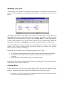
Note that Simulink gives a brief explanation of the block's function in the top portion of this
window. In the case of the Gain block, the signal input to the block (u) is multiplied by a
constant (k) to create the block's output signal (y). Changing the "Gain" parameter in this
window changes the value of k.
For our system, we will let k = 5. Enter this value in the "Gain" field, and click "OK" to close
the window.
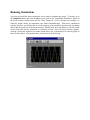
The Scope block simply plots its input signal as a function of time, and thus there are no system
parameters that we can change for it. We will look at the Scope block in more detail after we
have run our simulation.
Connecting the Blocks
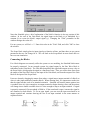
For a block diagram to accurately reflect the system we are modeling, the Simulink blocks must
be properly connected. In our example system, the signal output by the Sine Wave block is
transmitted to the Gain block. The Gain block amplifies this signal and outputs its new value to
the Scope block, which graphs the signal as a function of time. Thus, we need to draw lines from
the output of the Sine Wave block to the input of the Gain block, and from the output of the Gain
block to the input of the Scope block.
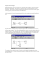
Lines are drawn by dragging the mouse from where a signal starts (output terminal of a block) to
where it ends (input terminal of another block). When drawing lines, it is important to make sure
that the signal reaches each of its intended terminals. Simulink will turn the mouse pointer into
a crosshair when it is close enough to an output terminal to begin drawing a line, and the pointer
will change into a double crosshair when it is close enough to snap to an input terminal. A signal
is properly connected if its arrowhead is filled in. If the arrowhead is open, it means the signal is
not connected to both blocks. To fix an open signal, you can treat the open arrowhead as an
output terminal and continue drawing the line to an input terminal in the same manner as
explained before.