1
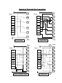
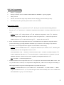
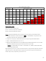
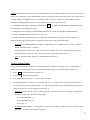
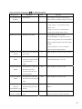
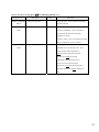
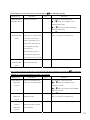
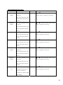
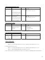
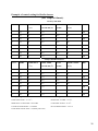
Ext.
Fan 1 Fan 2 Fan 3 Fan 4 Fan 5 Fan 6 Fan 7 Fan 8 Pump Timer Alarm
TEMPERATURE
PROGRAM
BATTERY
HUMIDITY %RH
1
2
3
4
5
6
7
8
9
PROGRAM
CANCEL
0
ENTER
NEXT
Model : UTI-200 R8
UTI-200R8 USER'S MANUAL (V2.0)
HuTek (Asia) Co., Ltd.
91 Soi Akkaphat (Thonglor 17), Vadhana, Bangkok 10110 THAILAND
T: +662 185 2831-4
F: +662 712 6098 E-mail: [email protected]
Web site: http://www.hutek-asia.com
1
Content
Components
General Specifications
Technical Specifications
Before Installation
Electrical diagram
Sensors Connection/placement
Sample of port and fan connection
Overview of UTI-200R8 control panel
General information
Entering data
Setting new Password
Self-test programming
Fan Setting Guide
Pump Setting Guide
T-curve setting Guide
Programming Guide
Alarm setting guide
Example of control settings for Broiler houses
Page #
3
3
4
5
6
7
8
9
10
10
10
11
11
12
13
15
25
26
2
Components
1.
2.
3.
Temperature Sensor
Humidity Sensor
UTI-200R8 control box with built-in battery back up
2
1
1
sets
set
set
General Specifications
•
•
•
•
•
•
•
•
•
•
•
•
•
Temperature display in oC or oF ,Relative Humidity in % RH
Operating range 0-70 oC, 25-99%RH
Two-line LCD display
Real time display for Temperature, Humidity and Heat Stress Index
Calibration program for temperature sensor, humidity sensor, and time/date
“self-test” program for all relays and ports
8-channel for fan controller
• Mode Fan 1-4
Temperature and timer control (pulse mode)
• Mode Fan 5-8
Temperature and heat-stress Index control (HSI)
• Optional Heating control by selecting Fan 8 in Heater mode
• Optional T-curve program. Can vary setting up to 8 Rearing stages from age 0 to 999 days
1 Channel for cooling: Controlling by temperature, humidity and timer (pulse mode)
1 channel for timer: On/Off, 8 steps per day used for lighting or sprinkler
Alarm system running on built-in rechargeable battery (12VDC 1.3AH). Can be set for low
temperature alarm, high temperature alarm, heat stress alarm, disconnected sensor, and power failure.
Password Enable (default password "2519")
Failed-safe system. In case of any mal-function, the unit will trigger the alarm and automatically
switch on Fan 1. “STANDBY” or “AUTO” mode
Can set ID and Description for each individual units (for optional centralized computer control)
• Data Upload/Download to and from different units
• Built-in memory for data recorder up to 14 days (672 records) can be displayed in LCD panel and
printed out
• Centralized computer control can control up to 100 houses (optional programming and accessories
sold separately)
3
Technical Specifications
Casing
Electrical
Temperature Sensors
Humidity Sensor
Output for Fan
Output for Cooling
Output for Timer
Output for Alarm
IP56
Voltage
Frequency
Power
Fuse
Operating range
Display digit
Accuracy
Operating range
Display digit
Accuracy
Output relay contact
Fuse
Control Mode
Output relay contact
Fuse
Control Mode
Output relay contact
Fuse
Control Mode
Output relay contact
Fuse
Control Mode
220 VAC
50
Hz
20
W
250 VAC, 500 ma fast blow
0-70 oC
0.1 oC
+1.0 oC
25-99 %RH
0.1 %RH
%RH
+5
8 outputs 220VAC, 5A
250 VAC, 4A fast blow
1-4: Temperature/ Pulse
5-8: Temperature/Heat Stress
1 output 220VAC, 5A
250 VAC, 4A fast blow
Temperature/Humidity/Pulse
1 output 220VAC, 5A
250 VAC, 4A fast blow
8 steps On/Off per day
250 VAC, 5A
250 VAC, 4A fast blow
Low/High Temp.
Heat Stress
Power failure
Equipment Mal-function
4
Before Installation
• For safety, always connect UTI-200R8 through breaker switches and always with ground wiring
•
•
•
•
Electrical wire should be at least 1mm in diameter
Choose suitable magnetic contactor size. Switch board panel should be of class IP56
Signal wire should be shield wire with at least 0.34mm in diameter
Shut-off the main breaker before installing or inspecting UTI-200R8 to prevent damage from electrical
surge
• Do not expose humidity sensor to water
5
ALARM
NC
220VAC
SIREN
12 VDC
C
NO
L
N
G
Coil
SIREN
12VDC
Coil
Coil
FAN 1
FAN2
FAN3
FAN 2
FAN1
FAN 3
Overload
FAN4
Overload
Coil
FAN 7
FAN 6
Overload
FAN 8
Overload
Coil
FAN5
FAN6
FAN7
FAN8
PUMP
Manaul
TIMER
Overload
Coil
Manaul Auto
Overload
Coil
Manaul Auto
Overload
Coil
Manaul Auto
Overload
Coil
Manaul Auto
Overload
Coil
Manaul Auto
Overload
COM
Manaul Auto
0VDC
Manaul Auto
V+
Manaul Auto
HUM
Switch Fan 8 Switch PUMP Switch TIMER
TC -
Manaul Auto
0VDC
Switch Fan 7
TC +
Auto
TIMER
Switch Fan 6
PUMP
COM
Switch Fan 5
FAN 5
FAN 4
Switch Fan 4
TC -
Switch Fan 3
0VDC
Switch Fan 2
TC +
Switch Fan 1
-+
Relay Board : UTI-200 R8
Electrical Diagram
NEUTRAL 0VAC
LINE 220VAC
6
Sensors Connection/ Placement
TC 0VDC
TC +
V+
HUM
0VDC
Green
Black
Shield
Temperature Sensor #2
COM
4 CORE
TIMER
PUMP
COM
FAN 8
FAN 7
FAN 6
FAN 5
Humidity Sensor
Green
Black
White
Red
Shield
FAN 4
FAN 3
FAN 2
FAN 1
Temperature Sensor #1
-+
SIREN
12VDC
NC
ALARM
C
NO
220VAC
L
N
G
Green
Black
Shield
White
Red
Shield
Relay Board : UTI-200 R8
TC 0VDC
White
Red
Shield
White
Red
4 CORE
TC +
7
Sample of Port and Fan Connection
1
Ports
1
Ports
F1
F1
2
2
F2
F2
F3
F3
3
3
F4
F5
F4
4
F5
5
4
F6
F6
F7
6
F7
5
F8
F8
7
6
6 Fans House
8
Fans
Fans
1
Ports
F1
2
F2
Fans
8 Fans House
1
Fans
2
Ports
F1
3
F2
3
F3
4
F3
F4
4
F4
5
F5
5
F5
6
F6
F6
6
F7
F8
7
HEATER
7
F7
F8
8
8
9
10
8 Fans and Heater House
10 Fans House
8
Overview of UTI-200R8 control panel
Temperature Display/
Red Screen
Output Relay Status
Humidity Display/
Green Screen
LCD panel
Scrolling
buttons
Numeric key pads
(Please Refer to
Programming guide)
Confirm/Execute
button
Back-up Battery status
Blinking: Charging
Light on: Running on Battery
Changing pre-set choices,
eg. Selecting month
Programming Status
Light On: Programming enable
9
General Information
• The unit is set for automatic delayed after power failure (default is 3 seconds, can be programmed
differently, function 7 Æ TIMER DELAY ON STATUS. Please refer to programming guide)
• Default universal password is "2519"
• Disable timer function (pulse mode). Set Time OFF = 0
Entering Data (refer to programming guide for complete list of functions)
1.
2.
3.
4.
5.
Press number corresponded to the desired function then press "program"
1
•
Calibrate Sensor
2
•
Time and Date
3
•
Fan 1 – 4 Temperature control and Timer control (Pulse mode)
4
•
Fan 5 – 8 Temperature control and Heat Stress control
5
•
Cooling (Pump) control by Temperature/ humidity/ Timer (pulse)
6
•
Timer (lighting) 8 steps per day
7
•
Function Parameter Set
8
•
Display Record Data / Print Record Data
9
•
Display Record MIN / MAX Value, Print Record MIN/MAX Value
0
•
Select Display oF or oC
NEXT
•
Display growth day and current mode
use Δ or ∇ to scroll to the desired sub functions then press "program".
Enter new value using numeric key pad then press "program" or "enter" to confirm the new value.
For pre-set choices, e.g. month, use "next" to scroll to the desired value.
Press "cancel" should you do not wish to enter the new value.
Setting new Password
1.
2.
3.
4.
Press "7" Æ "program"
Use up and down key pad to scroll to "MODE PASSWORD SETUP" Æ press program
Enter old password or universal password "2519"
Enter new password
10
Self-Test Programming
1.
2.
3.
4.
5.
Press "7" Æ "program"
Press up or down to scroll to "TEST OUTPUT RELAY CONTROL" Æ press "program"
Enter password
The unit will test all the output relay channels and also charging system for back-up battery
Should any relay fail to perform, please contact us for more details.
Fan Setting Guide
1. Last fan port should be set to open below 28oC-30oC. Work your way backward with setting difference
between 1.0oC-1.5oC between port. “Difference Temperature (DT CLOSE)” for each port should be set at 0.51.0oC
Example: FAN8 = 28oC, each port differs 1.0oC and “Difference Temperature” set at 0.5oC. Therefore,
FAN8 will open at 28oC, FAN7 will open at 27oC, FAN6 will open at 26oC,…FAN1 will open at 21oC
FAN8 will close at 27.5oC, FAN7 will close at 26.5oC,…, FAN1 will close at 20.5oC
2. FAN1-4 should be used for temperature below 25oC and should be use in conjunction with pulse mode to
prevent suffocating by providing minimum ventilation at pre-set interval. If the setting is only based on
temperature, at lower temperature there might be too little number of fan working.
Example: FAN4 set TEMP OPEN at 24oC, “Temperature difference (DT CLOSE)” at 0.5oC. Without pulse
setting, FAN4 will close if temperature is below 23.5oC
If VEN PULSE F4 T ON = 3 minutes, set VEN PULSE F4 T OFF = 5 minutes, set TEMP CLOSE at 16oC
Even the temperature falls below 23.5oC, FAN4 will open for 3 minutes and close for 5 minutes to provide
minimum ventilation. The fan will only close completely if temperature falls below 16oC.
Note: Set TOFF = 0 to deactivate pulse mode
3. FAN5-8 should be used for temperature above 25oC in conjunction with Heat Stress Index (HSI) control. This
is to prevent stress out caused by low temperature but high humidity. HSI control will keep the fan running if
HSI is higher than the set point even the temperature is lower than the set point.
Example: set TEMP OPEN at 27oC, DT CLOSE at 0.5oC and HS.OPEN = 170, DHS.CLOSE = 2. When
temperature falls below 26.5oC (79.7oF), fan will stop but if the relative humidity rises over 90.3%RH which
causes HSI Index to go up to 170, fan will open.
11
Temperature
o
o
C
F
15.6
60
18.3
65
21.1
70
23.9
75
26.7
80
29.4
85
32.2
90
35.0
95
60
120
125
130
135
140
145
150
155
65
125
130
135
140
145
150
155
160
HEAT STRESS INDEX TABLE
Relative Humidity (%RH)
70
75
80
85
130
135
140
145
135
140
145
150
140
145
150
155
145
150
155
160
150
155
160
165
155
160
165
170
160
165
170
175
165
170
175
180
90
150
155
160
165
170
175
180
185
95
155
160
165
170
175
180
185
190
99
159
164
169
174
179
184
189
194
Pump Setting Guide
There are two options for PUMP control
Option1: Controlled by Temperature and Humidity
Option2: Controlled by Temperature and timer
Option1 (Temperature and Humidity control) is suitable for most case especially in hot and humid climate.
1.1. Set MODE CTRL HUM. in Function Parameter Set 7 to 1. USE HUMIDITY. Pump function will be
controlled by temperature sensor and humidity sensor.
1.2. Temperature to start pump (T OPEN PUMP) should be set at equal or higher than TEMP OPEN F8.
1.3. DIFF T. CLOSE PUMP should be set at 0.5oC-1oC
1.4. HIGH H CLOSE PUMP should be set at 80-85%RH and LOW H OPEN PUMP should be set at 70-75%RH.
The difference %RH between pump activation and stop should be at least 5%RH
Example: Set T OPEN PUMP at 28oC, DIFF T. CLOSE PUMP 1.0oC, HIGH H CLOSE PUMP 85%RH,
LOW H OPEN PUMP 80%RH.
When temperature goes up to 28oC, pump will open and evaporative cooling will reduce temperature and increase
%RH at the same time. When %RH reaches 85%, pump will stop and reactivate again when %RH falls below
80%RH. Pump will stop if temperature goes down below 27oC
12
Option2 (Temperature and Timer control) is suitable ONLY for hot and dry climate where there is the need to save
water. User should have a good understanding of how evaporative cooling system works since this option will not
consider reading from humidity sensor in controlling pump. Therefore, it cannot avoid the situation of high
temperature and high humidity which could cause HSI to go up beyond desirable level.
1.1. Set MODE CTRL HUM. in Function Parameter Set 7 to 2. NOT USE HUMIDITY. Pump function will
be controlled only by temperature sensor.
1.2. Temperature to start pump (T OPEN PUMP) should be set at equal or higher than TEMP OPEN F8.
1.3. DIFF T. CLOSE PUMP should be set at 0.5oC-2.0oC
1.4. PUMP T PULSE T ON and PUMP T PULSE T OFF should be set according to the local condition by
allowing enough pump operating time to moisten the evaporative cooling panel thoroughly
Example: set T OPEN PUMP 28oC, DIFF T. CLOSE PUMP 1.0oC, PUMP T PULSE T ON = 3 minutes,
PUMP T PULSE T OFF = 5 minutes
When temperature rises to 28oC, pump will be on for 3 minutes and off for 5 minutes and then on again
according to pre-set interval. Pump will be closed when temperature falls below 27oC
Note: To deactivate pulse function, set PUMP T PULSE T OFF = 0
T-curve Setting Guide
T-curve setting enables the controller to perform differently according to the rearing period. This program is
suitable with “All In All Out process” such as Poultry Broiler, Poultry Layer, Poultry Breeder, Swine etc.
1. press 3 to select function control Fan 1-4
2. press Δ or ∇ for STATUS T-CURVE
3. press “PROGRAM” and press “1” choose USE T-CURVE
4. Input beginning age for each stage. ST1 always start with “0”. ST2 must have age value greater than ST1.
ST3 must have age value greater than ST2…etc. Any latter stage that has age value smaller than the previous
stage will be ignored. For any stage not in use, input “0”
Example 1: Poultry Broiler 45 days. 2 rearing periods. First period from 0 to 21 daysold. Second period
from 22 to 45 daysold. Use the following inputs.
ST1 AGE GROWTH = 0
ST2 AGE GROWTH = 22
ST3 to ST8 = 0
Example2: Poultry Breeder. 3 rearing periods. First period 4 weeks. Second period up to 10 weeks. Final
period up to 68 weeks. Use the following inputs
13
ST1 AGE GROWTH = 0
ST2 AGE GROWTH = 29 days
ST3 AGE GROWTH = 70 days
ST4 to ST8 = 0
5. There will be new parameters for each ST in Function Control Fan 1-4, Function Control Fan 5-8 and
Function Control Pump and Alarm. ST AGE GROWTH will only need to be input once.
6. Check actual age by pressing “NEXT” and Δ or ∇ for “AGE GROWTH DAY”. It will start counting from
the date input the program. To reset the value for starting the new flock, press “PROGRAM” and enter the
value of AGE GROWTH DAY = 0
Note: To deactivate T-curve function,
1. press 3 to select function control Fan 1-4
2. press Δ or ∇ for STATUS T-CURVE
3. press “PROGRAM” and press “2” choose NOT USE T-CURVE
14
Programming Guide
Button 1 "Calibrate Sensor" function [press Δ∇ for following options]
Message LCD
Description
Unit
Instruction
TEMP.
Temperature reading
ºC
Press "Program" Æ enter password Æ
SENSOR 1
from Temp. Sensor # 1
LCD shows “CALIBRATE TEMP.1”
CALIBRATE
Calibrate Temp. Sensor
ºC
Input value then press "program" to enter
TEMP.1
#1
the newly calibrated value
TEMP.
Temperature reading
ºC
Press "Program" Æ enter password Æ
SENSOR 2
from Temp. Sensor # 2
LCD shows “CALIBRATE TEMP.2”
CALIBRATE
Calibrate Temp. Sensor
ºC
Input value then press "program" to enter
TEMP.2
#2
the newly calibrated value
HUMIDITY
%RH reading from
%R
Press "Program" Æ enter password Æ
SENSOR
Humidity Sensor
H
LCD shows “CALIBRATE HUM.”
CALIBRATE
Calibrate Humidity
%R
Input value then press "program" to enter
HUM.
Sensor
H
the newly calibrated value
Button 2 "Time and date" Function [press Δ∇ for following options]
Message LCD
Description
Unit
Instruction
TIME
Show current time and
Press "program" Æ LCD shows “SETUP
CURRENT
date
CLOCK”
SETUP
Set up new date and
Input value, use up down button to move
CLOCK
time
cursor then press "program" to enter the
newly calibrated value
15
Button 3 Function Control Fan 1 – 4[press Δ∇ for following options]
Message LCD
Description
Unit
Instruction
Press “PROGRAM” and
STATUS TActivate or deactivate T“1” USE T-CURVE to activate this
CURVE
curve function
function (ST1 through ST8 will be
(customized control for
available for other parameter settings)
each rearing periods)
“2” NOT USE T-CURVE to deactivate
this function (only ST1 will be available)
ST1 AGE
Age (day) to begin first
DAY
Press “PROGRAM” to set beginning age
GROWTH
rearing stage
for each rearing stage. ST1 always set = 0
Value for the following stage must be
larger than the previous stage (ST2>ST1,
ST3>ST2…etc.) If value of the following
stage is smaller than the previous stage,
the programming on that stage will be
ignored). For unused stage, enter value =
0
ST1 TEMP. OPEN Temperature that triggers Fan
ºC
Press "Program" to enter new value
F1
1 operation
ST1 TEMP. OPEN Temperature that triggers Fan
ºC
Press "Program" to enter new value
F2
2 operation
ST1 TEMP. OPEN Temperature that triggers Fan
ºC
Press "Program" to enter new value
F3
3 operation
ST1 TEMP. OPEN Temperature that triggers Fan
ºC
Press "Program" to enter new value
F4
4 operation
ST1 DT CLOSE F 1 Temp. diff. (from open temp)
That will close Fan 1 and enter
pulse mode
ST1 DT CLOSE F 2 Temp. diff. (from open temp)
That will close Fan 2 and enter
pulse mode
ºC
Press "Program" to enter new value
ºC
Press "Program" to enter new value
16
Button 3 Function Control Fan 1 – 4[press Δ∇ for following options] Con’t
Message LCD
Description
Unit
Instruction
ºC
Press "Program" to enter new value
ST1 DT CLOSE F 3 Temp. diff. (from open temp)
That will close Fan 3 and enter
pulse mode
ST1 DT CLOSE F 4 Temp. diff. (from open temp)
That will close Fan 4 and enter
pulse mode
ST1 VEN PULSE F Pulse mode for Fan 1
1 TON
(duration fan 1 on)
ST1 VEN PULSE F Pulse mode for Fan 2
2 TON
(duration fan 2 on)
ST1 VEN PULSE F Pulse mode for Fan 3
3 TON
(duration fan 3 on)
ST1 VEN PULSE F Pulse mode for Fan 4
4 TON
(duration fan 4 on)
ST1 VEN PULSE F Pulse mode for Fan 1
1 TOFF
(duration fan 1 off)
ºC
Press "Program" to enter new value
Min
ST1 VEN PULSE F Pulse mode for Fan 2
2 TOFF
(duration fan 2 off)
Min
ST1 VEN PULSE F Pulse mode for Fan 2
3 TOFF
(duration fan 3 off)
Min
ST1 VEN PULSE F Pulse mode for Fan 2
4 TOFF
(duration fan 4 off)
Min
ST1 TEMP CLOS
F1
ST1 TEMP CLOS
F2
ST1 TEMP CLOS
F3
ST1 TEMP CLOS
F4
Min. temp to shut down fan 1
ºC
Press "Program" to enter new value, ON=
duration Fan 1 on
Press "Program" to enter new value, ON=
duration Fan 2 on
Press "Program" to enter new value, ON=
duration Fan 3 on
Press "Program" to enter new value, ON=
duration Fan 4 on
Press "Program" to enter new value, OFF=
duration Fan 1 off, enter "0" to cancel pulse
mode
Press "Program" to enter new value, OFF=
duration Fan 2 off, enter "0" to cancel pulse
mode
Press "Program" to enter new value, OFF=
duration Fan 3 off, enter "0" to cancel pulse
mode
Press "Program" to enter new value, OFF=
duration Fan 4 off, enter "0" to cancel pulse
mode
Press "Program" to enter new value
Min. temp to shut down fan 2
ºC
Press "Program" to enter new value
Min. temp to shut down fan 3
ºC
Press "Program" to enter new value
Min. temp to shut down fan 4
ºC
Press "Program" to enter new value
Min
Min
Min
Min
17
Button 4 Function Control Fan 5 – 8[press Δ∇ for following options]
Message LCD
Description
Unit
Instruction
ST TEMP OPEN Temperature that triggers Fan
ºC
Press "Program" to enter new value
F5
5 operation
ST TEMP OPEN Temperature that triggers Fan
ºC
Press "Program" to enter new value
F6
6 operation
ST TEMP OPEN Temperature that triggers Fan
ºC
Press "Program" to enter new value
F7
7 operation
ST TEMP OPEN Temperature that triggers Fan
ºC
Press "Program" to enter new value
F8
8 operation
ST1 DT CLOSE F 5 Temp. diff. (from open temp)
ºC
Press "Program" to enter new value
That will close Fan 5
ST1 DT CLOSE F 6 Temp. diff. (from open temp)
ºC
Press "Program" to enter new value
That will close Fan 6
ST1 DT CLOSE F 7 Temp. diff. (from open temp)
ºC
Press "Program" to enter new value
That will close Fan 7
ST1 DT CLOSE F 8 Temp. diff. (from open temp)
ºC
Press "Program" to enter new value
That will close Fan 8
Press "Program" to enter new value
ST1 HS.OPEN F5 Heat Stress value that triggers
fan 5
ST1 HS.OPEN F6
Heat Stress value that triggers
fan 6
Press "Program" to enter new value
ST1 HS.OPEN F7
Heat Stress value that triggers
fan 7
Heat Stress value that triggers
fan 8
Press "Program" to enter new value
Heat Stress diff. To close fan 5
Press "Program" to enter new value
Heat Stress diff. To close fan 6
Press "Program" to enter new value
Heat Stress diff. To close fan 7
Press "Program" to enter new value
Heat Stress diff. To close fan 8
Press "Program" to enter new value
ST1 HS.OPEN F8
ST1 DHS.CLOSE
F5
ST1 DHS.CLOSE
F6
ST1 DHS.CLOSE
F7
ST1 DHS.CLOSE
F8
Press "Program" to enter new value
18
Button 5 Function Control pump and alarm [press Δ∇ for following options]
Message LCD
Description
Unit
Instruction
ST1 T OPEN PUMP Temperature that
ºC
Press "Program" to enter new value
triggers pump
ST1 DIFF T.CLOSE Temp. diff to shutdown
ºC
Press "Program" to enter new value
PUMP
pump
ST1 PUMP T PULSE Pulse mode for pump, on =
Min
Press "Program" to enter new value, ON=
duration of pump in operation
T ON
duration of pump in operation
%RH
Press "Program" to enter new value, OFF=
duration of pump stop (enter "0" to cancel pulse
mode)
Press "Program" to enter new value
%RH to operate pump
%RH
Press "Program" to enter new value
Temp to activate high
temp alarm
Temp to activate low
temp alarm
Duration alarm ON
Duration alarm OFF
ºC
Press "Program" to enter new value
ºC
Press "Program" to enter new value
Sec
Sec
Press "Program" to enter new value
Press "Program" to enter new value
ST1 PUMP T PULSE Pulse mode for pump, off =
T OFF
duration of pump stop
operation
ST1 HIGH H CLOSE %RH to stop pump
PUMP
ST1 LOW H OPEN
PUMP
HIGH TEMP.
ALARM
LOW TEMPE.
ALARM
TIME ON SIREN
TIME OFF SIREN
Min
19
Button 6 Function Pre-set Timer [press Δ∇ for following options]
Message LCD
Description
Unit
Instruction
TIMER PORT ON 1 Time step 1 ON
Press "Program" to enter new value
TIMER PORT OFF 1 Time step 1 OFF
Press "Program" to enter new value
TIMER PORT ON 2 Time step 2 ON
Press "Program" to enter new value
TIMER PORT OFF 2 Time step 2 OFF
Press "Program" to enter new value
TIMER PORT ON 3 Time step 3 ON
Press "Program" to enter new value
TIMER PORT OFF 3 Time step 3 OFF
Press "Program" to enter new value
TIMER PORT ON 4 Time step 4 ON
Press "Program" to enter new value
TIMER PORT OFF 4 Time step 4 OFF
Press "Program" to enter new value
TIMER PORT ON 5 Time step 5 ON
Press "Program" to enter new value
TIMER PORT OFF 5 Time step 5 OFF
Press "Program" to enter new value
TIMER PORT ON 6 Time step 6 ON
Press "Program" to enter new value
TIMER PORT OFF 6 Time step 6 OFF
Press "Program" to enter new value
TIMER PORT ON 7 Time step 7 ON
Press "Program" to enter new value
TIMER PORT OFF 7 Time step 7 OFF
Press "Program" to enter new value
TIMER PORT ON 8 Time step 8 ON
Press "Program" to enter new value
TIMER PORT OFF 8 Time step 8 OFF
Press "Program" to enter new value
Note
1) Timer will be operated according to time scale 0:01 hr – 24:00 hour per day . Do not set overlapping clock in any
step
2) To switch off function in any step, enter "0:00" value
3) Incremental of time = 10 minutes. For example, 01.3 means 01:30 hour
20
Button 7 Parameter Setting [press Δ∇ for following options]
Message LCD
Description
Unit
Instruction
ID CONTROLLER ID for the unit
Press "Program" to enter new value (ONLY
NUMBER
need to set this for centralized computer control)
MODE CTRL TEMP Temperature control mode
Press "Program" to enter new value
1 Temp. Sensor1 = Control based on Temp.
Sensor 1 only
2 Temp. AV Sen 1&2 = Control based on
average value of Temp. Sensor 1 and 2
MODE CTRL HUM. Humidity control mode
Press "Program" to enter new value
1 USE HUMIDITY= Use humidity sensor to
control cooling operation (as per setting HIGH
HUM. CLOSE PUMP and LOW HUM. OPEN
PUMP)
2 NOT USE HUM. = Do not use humidity
sensor to control cooling operation
TIMER DELAY ON Delay timer for operating after
sec
Press "Program" to enter new value (3-180 sec)
STATUS
power failure
Press "Program" to enter new value
HEAT STRESS
Heat Stress Index start to be
( recommended setting = 168-170)
INDEX
recorded and trigger the alarm
( Heat Stress Index = º F +
%RH )
Min
Press "Program" to enter new value
TIME RECORD HS. Time duration of continuous
INDEX
Heat Stress that will be
recorded as Heat Stress into
the unit's memory
Min
Press "Program" to enter new value
TIME ALARM HS. Time duration of continuous
INDEX
Heat Stress that will trigger the
alarm
Required accessories (please contact us for more
Up-Load / Down-Load
DOWN OR
parameter setting from and to
UPLOAD
details)
PARAMETER SET the units
TEST OUTPUT Self diagnostic program for all
Press "Program" to enter password. Self
RELAY CONTROL relays
diagnostic program will start automatically
21
Button 7 Parameter Setting [press Δ∇ for following options] Con’t
Message LCD
Description
Unit
Instruction
MODE PASSWORD Set up new password
Press “Program”, enter old password and then
SETUP
set new password
MODE FUNC.
Select Control mode for Fan 1
Press "Program" to enter new value
FAN1
1 FAN 1 STAND BY = Fan 1 will operate
continuously for minimum ventilation
regardless of setting
2 FAN 1 AUTO = Fan 1 will operate only when
there is malfunction on UTI controller
MODE FUNC.
Set control mode for Fan 8
Press “Program” to enter new value
FAN8
1 MODE FAN to use this port as fan. Port
will be activated when temperature is
higher than the set point and stop when
temperature is below the set point
2 MODE HEATER to use this port as
heater. Port will be activated when
temperature is lower than the set point and
stop when temperature is higher than the set
point
22
Button 8 Display recorded data/ Print recorded data [press Δ∇ for following options]
Message LCD
Description
Unit
Instruction
MODE DISPLAY Display recorded data
Press "Program" Mode Record Data
RECORD DATA
▲ or ▼ shows LCD “DISPLAY ALL
DISP.RECORD DATA”
▲ or ▼ shows LCD “GET DATE TIME
DISP.RECORD DATA”
DISPLAY ALL Shows all Recorded Data:
▲ or ▼ for next record. Press "cancel" or
DISP.RECORD Upper-left of LCD shows date,
"enter" or "program" to exit this screen
Lower-left of LCD shows
DATA
%RH, Upper-right of LCD
shows Temp. from sensor #1,
Lower-right shows Temp.
from sensor #2.
Red screen shows hours of
time recorded, Green screen
shows minute of time recorded
Input date and time then press "program"
GET DATE TIME Search for data recorded in
DISP.RECORD specified date and time
DATA
Button 9 Function Display Record MIN / MAX Value and Print Record MIN/MAX Value[press Δ∇ for following
options] (see **Recorded MIN/MAX value table** for reference)
Message LCD
MODE DISPLAY
MIN/MAX.
VALUE
Description
Show Recorded MIN/MAX
Value (refer to min/max table)
DISPLAY ALL
MIN/MAX.
VALUE
GET DATE
MONTH
MIN/MAX.
VALUE
Show all Recorded
MIN/MAX Value
Search for Recorded
MIN/MAX Value at specific
date and month
Unit
Instruction
Press "Program" Mode Record Data
▲ or ▼ shows LCD “DISPLAY ALL
MIN/MAX. VALUE”
▲ or ▼ shows LCD “GET DATE MONTH
MIN/MAX. VALUE”
▲ or ▼ for next record. Press "cancel" or
"enter" or "program" to exit this screen
Input date and month then press "program"
23
**Recorded MIN/MAX Value Table**
Message LCD
Description
MAXIMUM
Max. daily temperature (Temp
TEMP.1
sensor #1)
Red screen shows hour of day,
Green screen shows minute of
the day
MINIMUM
Min. daily temperature (Temp
TEMP.1
sensor #1)
Red screen shows hour of day,
Green screen shows minute of
the day
MAXIMUM HUM. Max. daily humidity
Red screen shows hour of day,
Green screen shows minute of
the day
MINIMUM HUM. Min. daily humidity
Red screen shows hour of day,
Green screen shows minute of
the day
MAXIMUM
Max. daily temperature (Temp
TEMP.2
sensor #2)
Red screen shows hour of day,
Green screen shows minute of
the day
MINIMUM
Min. daily temperature (Temp
TEMP.2
sensor #2)
Red screen shows hour of day,
Green screen shows minute of
the day
NUMBER ALARM Number of Heat Stress
HS.
happening during the day (as
pre-set in Function # 6,
parameter set, TIME ALARM
HS. INDEX)
Unit
ºC
Instruction
▲ or ▼ to show next record. Press
"Cancel", "Enter", "Program" to exit screen
ºC
▲ or ▼ to show next record. Press "Cancel",
"Enter", "Program" to exit screen
%RH
▲ or ▼ to show next record. Press "Cancel",
"Enter", "Program" to exit screen
%RH
▲ or ▼ to show next record. Press "Cancel",
"Enter", "Program" to exit screen
ºC
▲ or ▼ to show next record. Press "Cancel",
"Enter", "Program" to exit screen
ºC
▲ or ▼ to show next record. Press "Cancel",
"Enter", "Program" to exit screen
▲ or ▼ to show next record. Press "Cancel",
"Enter", "Program" to exit screen
24
**Recorded MIN/MAX Value Table** Con’t
Message LCD
Description
TIME ALL HS. Duration of longest Heat
Stress.
Red screen shows hour of day,
Green screen shows minute of
the day when it happened
MAXIMUM HS. Max. Heat Stress.
Red screen shows hour of day,
Green screen shows minute of
the day when it happened
Button 0 Function Select Display
Message LCD
Description
DEGREE TEMP. Choose whether to show
temperature in Celsius or
Fahrenheit
Unit
Min.
Instruction
▲ or ▼ to show next record. Press "Cancel",
"Enter", "Program" to exit screen
▲ or ▼ to show next record. Press "Cancel",
"Enter", "Program" to exit screen
Unit
º C or º F
Button “NEXT” display growth day and current mode
Message LCD
Description
Unit
Day
AGE GROWTH Show age growth since last
programming or last reset
DAY
_ _ _ DAY
Instruction
▲ or ▼
“1.CELSIUS DEG”
“2.FAHLENHEIT DEG”
Press "program"
Instruction
Press “Program” to change the data
To reset and start over for new flock, enter value
=0
Alarm setting guide
For Poultry Broiler 0-21days:
Button “5”: Low temp alarm should be set at 18-20oC. High temp alarm should be set at 37-39oC
For Poultry Broiler 22 days onward:
Button “5”: Low temp alarm should be set at 10-12oC. High temp alarm should be set at 33-35oC
Button “7”, HEAT STRESS INDEX alarm should be set at 168-170*
*Note*: Should take into account ambient environment, type of animals for establishing alarm setting parameters
25
Example of control setting for Broiler houses
(For Tropical climate)
Fan #
PORT
1
2
3
4
5
6
7
8
F7
F3
F5
F1
F2
F6
F4
F8
Fan #
PORT
1
2
3
4
5
6
7
8
F7
F3
F5
F1
F2
F6
F4
F8
TEMP OPEN
F (oC)
34
30
32
28
29
33
31
35
TEMP OPEN
F (oC)
27
23
25
21
22
26
24
28
1-21 days-old chick
DIFF. TEMP
TON/
CLOSE PF (oC) TOFF
1.0
0.5
2/5
1.0
0.5
2/5
0.5
2/5
1.0
0.5
2/5
1.0
22 days-old chick onward
DIFF. TEMP
TON/
CLOSE PF (oC) TOFF
1.0
0.5
3/5
1.0
0.5
3/5
0.5
3/5
1.0
0.5
3/5
1.0
Cooling Setting:
TEMP.OPEN PUMP = 27 - 28 oC
HIGH HUM. CLOSE PUMP = 80-85%RH
LOW HUM. OPEN PUMP = 75-80%RH
PUMP TEMP. PLUSE TOFF = 0 (disable pulse mode)
TEMP CLOSE
F (oC)
HSI
170
22
170
20
21
170
23
170
TEMP CLOSE
F (oC)
HSI
170
15
170
13
14
170
16
170
Alarm Setting:
HIGH TEMP. ALARM = 32-34oC
LOW TEMP ALARM = 10-12oC
HEAT STRESS INDEX = 168-170
26