1
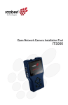
IP Camera Tester
User Manual
Ver1.2
IP Camera Tester User Manual
Regulation
This device complies with Part 15 of the FCC Rules.
Operation is subject to the following two conditions:
(1)This device may not cause harmful interference, and
(2)This device must accept any interference received,
including interference that may cause undesired operation.
This symbol on the product or on its packaging indicates
that this product shall not be treated as household waste in
accordance with Directive 2002/96/EC. Instead it shall be
handed over to the applicable collection point for the
recycling of electrical and electronic equipment. By proper
waste handling of this product you ensure that it has no
negative consequences for the environment and human
health, which could otherwise be caused if this product is
thrown into the garbage bin. The recycling of materials will
help to conserve natural resources.
For more details information about recycling of this product,
please contact your local city office, your household waste
disposal service or the shop where you purchased the
product.
Compliance is evidenced by written declaration from our
suppliers, assuring that any potential trace contamination
levels of restricted substances are below the maximum
level set by EU Directive 2002/95/EC, or are exempted due
to their application.
1
Video Tester User Manual
Table of Contents
1.
2.
Overview .....................................................................................................................3
Screen Layout ............................................................................................................4
Status Icons .................................................................................................................4
Buttons.........................................................................................................................4
3.
4.
Touch Panel Calibration............................................................................................8
AV In/Out (Analog Video In/Out) .............................................................................10
4.1 AV In—Live View ..............................................................................................10
4.1.1 Live View—Speed Dome Camera..........................................................10
4.1.2 Live View—Fixed Camera......................................................................12
4.2 AV Out (Color Test Pattern)..............................................................................13
5.
6.
7.
8.
Setup-AV (Brightness, Sharpness, Contrast)........................................................14
Setup-Dome..............................................................................................................15
Cable Test (CAT5) ....................................................................................................17
IP Camera (Live View)..............................................................................................19
8.1 Connect (Direct Connecting).............................................................................19
8.2 Device Search...................................................................................................21
9.
Setup-IP ....................................................................................................................24
9.1 Setup-IP Connection (Altering Camera Settings)..............................................26
9.2 Setup-IP Camera (Loading the Network Settings) ............................................27
10. Setup-Snapshot .......................................................................................................28
11. PoE Setup .................................................................................................................31
12. Setup-Audio (Tester) ...............................................................................................33
13. Setup-System ...........................................................................................................35
Appendix: Technical Specification ................................................................................39
2
IP Camera Tester User Manual
1.
Overview
The IP Camera Tester combines an analog video tester, PTZ camera controller,
and IP digital video tester into a single hand-held device, utilizing an ultra-bright,
high-resolution 3.5” color LCD screen, which makes all camera adjustments a
snap.
IP Camera Tester benefits users by providing various network protocol
compatibility. With customized built-in codec, IP Camera Tester is capable of
decoding video streaming simultaneously, allowing users to view and to adjust
focus on the monitor. The Tester also operates on the NTSC/PAL TV system by
standard BNC video input and output. Moreover, it has a phone-jack that allows
users to test for audio if available. Furthermore, IP Camera Tester runs off of a
rechargeable battery that takes approximately four hours to charge, and
provides the Tester with up to three hours of operating time.
Blending functionality and compatibility, IP Camera Tester is a versatile video
tester for both analog and IP applications.
Product Features
z Built-in 3.5 inch LTPS LCD monitor with QVGA resolution
z 10 / 100 Ethernet with RJ45 connector
z PTZ control / command parse via Ethernet and RS-485 interface
z Built-in touch panel / keypad.
z High capacity Lithium battery
z UTP cable test
z
z
z
MJPEG video compression
NTSC/PAL video in and out / Audio in / speaker out
Video looping function
3
Video Tester User Manual
2.
Screen Layout
Home Screen
The Home Screen of the IP Camera Tester is shown as follows:
Status Icons
Battery Status
Indicates the battery level and charging status.
Buttons
Return to the Home Screen.
Home Screen
When Tester is connected with a PoE-enabled IP
Camera, if press the PSE button to enable it lightened,
PSE
the camera will drain power from Tester’s internal
battery.
Press this button to go back to the last page.
Return
Enter a function’s submenu or to save setup
Enter/Save
4
IP Camera Tester User Manual
Check video displayed on the LCD screen from the
analog camera’s video output.
AV In
Press the button and enter the video generating mode,
which contains various color test patterns for users to
check video input of the external display device.
AV Out
Directly connect to the IP Camera with one touch.
Connect
Ideal for testing multiple IP Cameras.
Tap this button,
and all the IP Cameras in the network can be found.
specific camera from the IP
address/MAC address list.
Users have to access [Setup]-[Setup IP]-[Setup IP
connection] for choosing camera type. And relative
IP cameras will be filtered out.
Then
IP Camera
Device
Search
select
a
Detects the CAT5 cable for straight, crossover, shorts,
opens and miswire.
Cable Test
Select whether to enable Power over Ethernet (PoE)
when booting up. PoE auto-shutdown time can also be
specified, which allows to conserve the Tester’s battery
PoE Setup
power.
Various setups for cameras and the IP Camera Tester
can be configured here. Each setup is shown in the
Setup
following section: Second Screen.
5
Video Tester User Manual
Second Screen
Press the Setup
button in the Home Screen, and you will be automatically
directed to the Second Screen as shown below.
Adjust analog video’s brightness, contrast and
sharpness.
Setup-AV
The IP Camera Tester’s IP address can be set here.
The IP Camera’s basic profile including IP address,
Setup-IP
connection
camera type, user name, password and streaming
relevant information is displayed. All the settings can
be altered here.
Configure
Setup-IP
Setup-IP
camera
the
IP
Camera’s
network
settings.
Additionally, it is allowed to load the relevant settings
from an IP Camera to the Tester.
Configure the Speed Dome Camera’s protocol, baud
rate and ID address.
Setup-DOME
Adjust the volume of IP Camera Tester.
Setup-Audio
6
IP Camera Tester User Manual
Preview and manage the snapshot files.
Setup-Snapshot
The IP Camera Tester’s system settings include LCD
brightness, firmware upgrade, factory default reset
Setup-System
and auto shutdown setup.
7
Video Tester User Manual
3.
Touch Panel Calibration
For initial access or after system reset, users will first enter the Touch Panel
Calibration mode (as shown below) before accessing to the Home Screen.
¾
¾
¾
8
Tap on the flashing cross on the left top of the screen.
Hit the other flashing cross located diagonally.
Then touch each flashing box coming out as instructed.
IP Camera Tester User Manual
The screen mode will switch to Home Screen (see the figure below) after
Touch Panel Calibration is completed.
9
Video Tester User Manual
4.
AV In/Out (Analog Video In/Out)
Users can test analog video in/out through the BNC IN/OUT connectors on the
side of the Tester as shown below.
4.1
AV In—Live View
Connect the BNC cable from the connected camera’s video output to the
Tester’s BNC IN port. Press the AV In
button in the Home Screen, and
users can view live video from the LCD screen.
4.1.1
Live View—Speed Dome Camera
Users can implement a Speed Dome Camera’s PTZ control in the live view
mode.
NOTE: Make sure the Speed Dome Camera’s RS-485 lines are correctly
connected to the Tester’s RS-485 terminal block, or PTZ control cannot
be manipulated here. For further details, please refer to the Tester’s
Setup Guide.
10
IP Camera Tester User Manual
Enabling PTZ Control Function
¾ Please press the Setup
button in the Home Screen and enter the
Second Screen.
¾ Tap the Setup-DOME
button and enter its setting page as shown
below.
¾ Select “Enable” from the Dome type drop-down list.
¾ Tap the Enter/Save
button to save the setting, and you will be
automatically directed to the Second Screen.
¾ Press the Return
button to return to the Home Screen.
Implementing PTZ Control
¾
Press the AV In
button in the Home Screen to enter the live view
mode. Meanwhile, there will be four arrow buttons displayed on the screen
as shown below.
11
Video Tester User Manual
¾
Tap the arrows on the screen to pan and tilt the camera. Press the
Up/Down Shift Keys (
,
) on the Tester’s button pad for zooming
in/out.
Users may adjust video brightness, contrast or sharpness for better live viewing.
These settings can be tuned in the Setup-AV
setting menu, which is
described in Chapter 4: AV Setup.
4.1.2
Live View—Fixed Camera
In the fixed camera’s live view mode, there will be the text “AV” displayed on the
right bottom of the screen as shown below.
Users may adjust video brightness, contrast or sharpness for better live viewing.
These settings can be tuned in the Setup-AV
setting menu, which is
described in Chapter 4: Setup-AV (Brightness, Sharpness, Contrast).
12
IP Camera Tester User Manual
4.2
AV Out (Color Test Pattern)
Users can verify a monitor’s color accuracy with the aid of color test patterns in
the AV Out
mode. Please connect the BNC cable to the Tester’s BNC
output (OUT) from an external monitor.
Press the AV Out
button in the Home Screen to enter the AV Out menu,
which contains eight color test patterns and a Bypass mode.
In the Bypass mode, live video displayed on the Tester can bypass to the
external display device.
All the patterns in the AV Out
mode can be cycled using the Left/Right
Shift Keys ( , ) of the Tester’s keypad or touching the pattern icon on the
LCD screen.
13
Video Tester User Manual
5.
Setup-AV (Brightness, Sharpness, Contrast)
In the Setup-AV
menu, users can adjust analog video’s brightness,
contrast or sharpness for favorable video display on the Tester’s LCD screen
under different operating circumstances.
Moving to Setup-AV Menu
¾
Press the Setup
button in the Home Screen and enter the Second
Screen.
¾
Tap the Setup-AV
button to enter the setting page, which is shown
below.
In the Setup-AV setting page, the live video is displayed on the upper screen.
14
IP Camera Tester User Manual
Adjusting Brightness/Sharpness/Contrast Value
¾
Move the slider bar by touching the screen or using the Tester’s Left/Right
Shift Keys ( , ).
Switching to Another Item
¾
Tap the AV Mode
button next to the slider bar or press the Tester’s
Up/Down Shift Keys to switch among Brightness, Sharpness and Contrast
setting.
button to save all the settings, and you will then
Press the Enter/Save
automatically directed to the Second Screen. Press the Return
button to
return to the Home Screen.
6.
Setup-Dome
In the Setup-DOME
menu, users can enable/disable PTZ control and
configure the Speed Dome Camera’s protocol, baud rate and ID address.
Moving to Setup-DOME Menu
¾
Press the Setup
button in the Home Screen and enter the Second
Screen.
¾
Tap the Setup-DOME
button to enter the setting page, which is shown
below.
15
Video Tester User Manual
Setting the Dome Type
¾ Select “Enable” or “Disable” from the Dome type’s drop-down list.
“Enable” means activating PTZ control on the IP Camera Tester, while
“Disable” indicates disabling PTZ control on the Tester.
Setting the Protocol
¾ Select the protocol for the Speed Dome Camera from the drop-down list.
Setting the Baud Rate
¾ Select the baud rate for the Speed Dome Camera from the drop-down list.
Setting the ID Address
¾ Enter the three-digit ID address.
Press the Enter/Save
button to save all the settings, and you will then
automatically directed to the Second Screen. Press the Return
return to the Home Screen.
16
button to
IP Camera Tester User Manual
7.
Cable Test (CAT5)
Users can check the RJ45 cable wiring with the supplied UTP Terminal Block
Setup for Testing
¾ Connect one end of the RJ45 connector to the UTP Terminal Block and the
other end to the CAT5 port at the side of the Tester.
Cable Testing
¾
Press the CAT5
¾
Tap the Test
button in the Home Screen.
button and wait for wiring detection.
Then the cable’s wire map will be displayed on the screen. Users can
check the RJ45 cable for its type (Straight/Crossover) and error connection
(Shorts, Open, Miswired).
17
Video Tester User Manual
¾
18
Press the Return
button to return to the Home Screen.
IP Camera Tester User Manual
8.
IP Camera (Live View)
The IP Camera Tester can automatically detect and recognize the IP Camera
that is connected to it. Please connect the IP Camera to the Tester’s LAN/PoE
port; plug in the IP Camera if not using PoE. For further information about PoE
use, please refer to Chapter 10: PoE Setup.
Automatic Changing IP Camera Tester’s IP Address
After the IP Camera is powered on, the IP Camera Tester’s IP address will be
automatically changed, which will be displayed on the screen.
Please refer to the following sections for connecting the IP Camera and viewing
live video in alternative ways.
8.1
Connect (Direct Connecting)
Enter the Menu for Direct Connecting
¾
Press the IP Camera
button in the Home Screen and enter the
submenu.
¾
Check the default camera settings displayed in the field under the Connect
button as shown below.
19
Video Tester User Manual
If there is any setting required to be altered, please go to the Setup-IP
connection
menu to change the related IP Camera settings. See the
section 8.1: Setup-IP Connection (Altering Camera Settings) for further
details.
Proceed to Connect the Camera
¾
Tap the Connect
button in the IP Camera submenu, and wait for
searching to finish. Then the live video will be displayed on the LCD
screen.
Digital PT Control
In the IP Camera’s live view mode, there will be the text “ZOOM” displayed on
the right bottom of the screen.
¾
Tap the text “ZOOM”, and the video will switch to the digital zoom mode (at
max. digital zoom ratio). Meanwhile, the text “PT” will be displayed on the
left bottom of the screen as shown below.
20
IP Camera Tester User Manual
¾
Press the Left/Right Shift Keys ( , ), and the image can be horizontally
shifted to the left/right with four steps respectively.
¾
Press the Up/Down Shift Keys (
,
), and the image can be shifted
upward/downward with four steps respectively.
To leave the Digital PT Control mode, simply tap the text “ZOOM.”
Exit the Viewing Mode
Press the ESC Key
on the Tester’s button pad to exit the live view mode,
and return to the IP Camera submenu.
IP Camera Profile Display
The IP Camera’s profile details including IP address, camera type, username,
password, etc. are shown on the IP Camera submenu.
8.2
Device Search
If there are multiple IP Cameras in the network, utilize Device Search to find all
of the cameras. The Device Search
button is in the IP Camera
submenu.
Implement Device Search
¾
Tap the Device Search
button, and wait for searching to finish. Then
you will enter the Device Search page as shown below.
21
Video Tester User Manual
¾
Select the IP address of the target camera from the device finding list on
the left top of the screen. Then press the
button below
the column of Password to start connecting. The live view video will be
displayed on the screen.
Digital PT Control
In the IP Camera’s live view mode, there will be the text “ZOOM” displayed on
the right bottom of the screen.
¾
Tap the text “ZOOM”, and the video will switch to the digital zoom mode (at
max. digital zoom ratio). Meanwhile, the text “PT” will be displayed on the
left bottom of the screen as shown below.
¾
Press the Left/Right Shift Keys ( , ), and the image can be horizontally
shifted to the left/right with four steps respectively.
¾
Press the Up/Down Shift Keys (
,
), and the image can be shifted
upward/downward with four steps respectively.
To leave the Digital PT Control mode, simply tap the text “ZOOM.”
22
IP Camera Tester User Manual
Exit the Viewing Mode
Press the ESC Key
of the Tester’s keypad to exit the live view mode, and
return to the IP Camera submenu.
23
Video Tester User Manual
9.
Setup-IP
Users can change the IP Camera’s setting, e.g. IP address, camera type, user
name, password, streaming format, network settings in the Setup-IP
submenus: Setup-IP connection
and Setup-IP camera
.
Move to Setup-IP connection and Setup-IP camera
¾
Press the Setup
button in the Home Screen and enter the Second
Screen.
¾
Tap the Setup-IP
submenu.
24
button in the Second Screen, and then enter the
IP Camera Tester User Manual
The Setup-IP connection
icon and Setup-IP camera
icon are in this
submenu.
25
Video Tester User Manual
9.1
Setup-IP Connection (Altering Camera Settings)
Press the Setup-IP connection
button and enter its setup menu, which is
like the following:
Specify Camera Settings
¾ Please specify the connected IP Camera’s IP address, camera type, user
name, password, streaming settings, etc. in each column using the stylus
touch pen.
Adding a Camera to List
¾
For adding a camera to the camera list, enter its model name in the
“Camera Profile” column and click the
button at the right side of this
column; while canceling a camera, select the camera to be deleted, and
click the
button.
Up to 128 IP Cameras can be assigned for testing.
Press the Enter/Save
menu, press the Return
26
button to save all the settings. To exit the setup
button.
IP Camera Tester User Manual
9.2
Setup-IP Camera (Loading the Network Settings)
For checking or altering the IP Camera’s network settings such as Subnet mask,
Default gateway, Primary DNS, Web server port, etc., users can go to the
Setup-IP camera
menu.
Press the Setup-IP camera
button and enter its setup menu, which is like
the following:
Load Settings from the IP Camera
Please press the
button on the top of the menu, and the IP
Camera’s network settings will be shown in the blank field.
NOTE: Make sure the target camera’s settings are correctly configured,
or the loading here will fail. For altering the camera settings, please go
back up one level by pressing the Return
Setup-IP connection
button. Then tap the
button and proceed to change camera
settings.
Reload the Settings to the IP Camera
If making any network setting changes, users may press the
button on the top of the menu for reloading the network settings to the camera.
Press the Enter/Save
button to save all the settings.
27
Video Tester User Manual
10.
Setup-Snapshot
The advanced snapshot function facilitates saving images in the assigned path
when necessary.
Implement Snapshot
¾
In the IP Camera’s live view mode, press the Snapshot key
on the
Tester’s front panel. Then enter the snapshot editing page as shown below.
Snapshot Editing
¾
Assign a storage location among the three options located on the very top
of the snapshot editing page: Tester, USB and SD for the snapshot. Click
on the button of the selected item.
¾
Enter the file name and description respectively for the snapshot.
¾
Press the Enter/Save
button, and the screen will automatically switch
to the Home Screen.
Files in USB/SD
For files saved in the USB drive or Micro SD card, they will be automatically
saved in the file folder named “IMAGE-DATA”, which is automatically created.
Each snapshot’s description can be found in the attached .txt file.
28
IP Camera Tester User Manual
Move to File Managing Page (Setup-Snapshot)
Users can preview each snapshot and copy/delete the image in the snapshot
file managing page.
¾
Press the Setup
button in the Home Screen.
¾
Click the Setup-Snapshot
button, and enter the snapshot file
managing page as shown below.
Image Preview
¾ In the Setup-Snapshot page, select the snapshot storage path (Tester,
USB or SD) where the saved files are located. Then all the files will be
¾
listed in the File List field.
Select one file within the File List, and the image will be displayed in the
Image Preview field as shown above.
Single File Copy
¾
Select the file to be copied from one storage path to another from the File
List.
¾
Press the File Copy
button located in the File Manager section below
the Image Preview field. Then the dialogue of request for selecting a
storage path will pop out.
¾
Click on the selected button and tap the Enter/Save
button.
All Files Copy
¾
Press the Select All
button located in the File Manager section below
the Image Preview field, and all the files in the list will be selected.
29
Video Tester User Manual
¾
Press the File Copy
button, and the request for selecting a storage
path will pop out.
¾
Click on the selected button and tap the Enter/Save
button. All the
snapshot files will be copied to the assigned storage path.
Single File Deletion
¾
Select the file to be deleted from the File List.
¾
Press the File Deletion
button located in the File Manager section
below the Image Preview field. Then the notice of confirmation will pop out.
¾
Click “OK” to allow deleting the file from the list.
All Files Deletion
¾
Press the Select All
button located in the File Manager section below
the Image Preview field, and all the files in the list will be selected.
¾
Press the File Deletion
button; and the notice of confirmation will pop
out.
¾
30
Click “OK” to allow deleting all the snapshot files from the list.
IP Camera Tester User Manual
11.
PoE Setup
The IP Camera Tester can function as the power sourcing equipment (PSE) and
deliver electricity to the PoE-enabled IP Camera.
IP Camera Tester as the PSE
¾
Connect the Ethernet cable from the IP Camera to the LAN/PoE Port on
the side of the Tester.
¾
Click on the PSE
button on the top right side of the screen; see the
figure below. The PSE indicator will be lit, which means the IP Camera is
extracting electricity power from the Tester’s battery.
Enable PoE after Tester Bootup
For users who wish to enable PoE in the meantime while the Tester is booting
up, please go to the PoE Setup page for setup.
¾
Press the PoE Setup
button in the Home Screen and enter its setting
page as shown below.
31
Video Tester User Manual
¾
Select “ON” from the drop-down list in “Enable PoE when booting”; the
Tester will deliver electricity to the IP Camera after system startup.
¾
Select the PoE auto-shutdown interval: 20 sec., 40 sec. or 60 sec. The
setup can aid conserving battery power when there is no IP Camera or
other device using the Tester as the PSE. The reminder of PoE shutdown
will pop out around 5 seconds in advance of shutting down.
¾
Click on the selected button and tap the Enter/Save
the settings mentioned above.
32
button for saving
IP Camera Tester User Manual
12.
Setup-Audio (Tester)
The IP Camera Tester’s audio volume can be adjusted in the Setup-Audio
page.
Move to the Setup-Audio Page
¾
Press the Setup
button in the Home Screen.
¾
Tap the Setup-Audio
button in the Second Screen and enter the
audio volume setting page as shown below.
33
Video Tester User Manual
Audio Volume Control
¾
To adjust the audio volume either by pressing the Left/Right Shift Keys
( , ) on the Tester’s button pad or touching the screen to move the slider
bar.
¾
Hit the
button next to the slider bar once, and the system will switch to
the mute mode.
¾
34
Tap the Enter/Save
button for saving the audio setting.
IP Camera Tester User Manual
13.
Setup-System
In the Setup-System page, users can adjust the brightness of the IP Camera
Tester’s LCD screen, implement firmware upgrade and restore all the system
settings to factory default.
Move to the Setup-System Page
¾
Press the Setup
button in the Home Screen.
¾
Tap the Setup-System
button in the Second Screen and enter the
Tester’s system setup page.
35
Video Tester User Manual
Tester Screen Brightness (Backlight) Adjustment
¾
Move the slider bar of Backlight. Greater value represents higher
brightness.
¾
If click on the Auto Control tick box, which is below the Backlight slider
bar, the screen’s brightness level will be fixed. Click on the Auto Control
button again and cancel the selection; then the slider bar above becomes
movable again.
Firmware Upgrade
Before implementing firmware upgrade, please make sure the firmware is
located in the path: upgrade\upd_dt01s\ in your USB drive.
¾
36
Click the
button, and the file selection dialogue will come out.
IP Camera Tester User Manual
¾
Press the
button, and the firmware in the USB drive
shall be found. The firmware details will be displayed in the blank field of
the file selection menu.
¾
Check the Complete upgrade tick box, and press the Enter/Save
button for upgrade startup. Then the notice of firmware upgrade
confirmation will pop up. Click “OK” and the firmware upgrade will proceed.
Reset to Factory Defaults
Users can restore the Tester system to factory defaults by implementing this
function.
¾
¾
Press the
button. Then the notice of resetting to factory default will
pop up. Click “OK” and continue.
The pop-up message of stating successful reset with request for system
reboot will display on the screen. Click “OK” and the Tester will get
shutdown.
Touch Panel Calibration after System Reset
Reboot the IP Camera Tester after system reset. You will be first directed to the
Touch Panel Calibration mode as shown below.
¾
¾
¾
Tap on the flashing cross on the left top of the screen.
Hit the other flashing cross located diagonally.
Then touch each flashing box coming out as instructed.
37
Video Tester User Manual
The screen mode will switch to Home Screen after Touch Panel Calibration is
completed.
Auto Shutdown
The system can be automatically shutdown after pre-determined time range
when idle.
¾ Select the specific time interval from the drop-down list for system auto
shutdown.
¾
38
To disable the Auto Shutdown function, please select “OFF” among the
options.
IP Camera Tester User Manual
Appendix: Technical Specification
IP Camera Tester
Color LCD Field Display
3.5" (320x240)
AV
Video Input
BNC x 1
Video Output
BNC x 1
Video Output Signal Format
Video ByPass & Color Patterns x 8
PTZ Camera
PTZ Control
RS-485 Ports
PTZ Camera Setting
Support Protocols
RS-485
R+, R-, T+, TPan, Tilt, Zoom, Manual Focus, Auto Focus
DSCP, Pelco D, Pelco P, AD422, Panasonic_C,
Panasonic_N, JVC, Fastrax 2
IP Camera
10/100 Mbps,
LAN In
48VDC In,
Power Bank In
LAN Out
IP Camera Setting
Support Brands
10/100 Mbps, 802.3af standard
IP address setting, Image setting
DynaColor, ACTi, A-MTK, Axis, Hunt, IQinVision,
Luxon, Planet, Pixord, Sanyo, Sony, Vivotek, Zavio
CAT-5
CAT-5 Port
1
Operation
Weight include Batteries
Battery Type
Charge Cycles @ 80% capacity
450 g
2 × 3.7 V Li-Ion, 2000mAh
> 300
Charging Time
3.5 Hrs
Operating Time
3 Hrs
Network
IP Setting
DHCP, Static IP
Size
Dimension (L×W×H)
170×99×38 mm
39
Video Tester User Manual
General Specifications
Electronic
Input Voltage
DC12V, 3A
Signal Format
NTSC or PAL
Video Level
1Vpp, 140IRE
PTZ Control
Data Communication
RS-485
IP Camera
Connection
RJ45
CAT-5 Cable Test
Detects
USB
Type
USB 2.0
SD Card
Type
SDHC supported
Input
Line In
Video
Audio
POE
40
Output
Straight/Cross Cables,
Open, Short, Miswire
Built-In Speaker
Phone Jack Φ3.5
By Pass / Power Bank
PoE LAN In
Device
Internal Battery