1
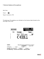
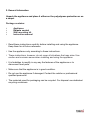
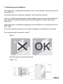
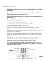
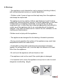
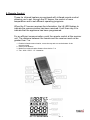
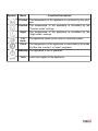
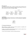
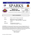
INSTRUCTION MANUAL
TOUCHSCREEN FAR
INFRARED HEATER
Sold & Distributed in the UK & Ireland by:
Funkyheat Ltd.
The Carlile Institute
Huddersfield Road
Meltham
HD9 4AE
www.funkyheat.co.uk
This appliance complies with European Directives:
2004/108/EC on electromagnetic compatibility.
2006/95/EC on low voltage.
2002/95/EC on the restrictions of the use of certain hazardous
substances.
CONTENTS
1.Technical features of the appliance
2. General Information
4
3. Positioning and installation 5
3.1 Wall mounting 7
3.2 Electrical connection 8
4. Warnings 9
4.1. Control panel (touch screen) 10
5. Remote Control 12
6. Cleaning and maintenance 18
7. Quick Controller Set-Up
19
3
2004/108/EC on electromagnetic compatibility.
2006/95/EC on low voltage.
2002/95/EC on the restrictions of the use of certain hazardous
substances.
1.Technical features of the appliance
hnical features of the appliance
0Hz
230V 50Hz
Class II
Degree of protection: IP24
of protection: IP24
The features of the appliance are indicated on the features label situated on the
rear edge of the cover.
atures of the appliance are indicated on the features label situated on the
dge of the cover.
:
Manufacturer's trademark or brand
678:
serial No.
XXXX : model……….. Manufacturer's trademark or brand
ory:………- type:………serial No.
e of protection:…..-Voltage:…… - Power……. 12345678:
type:………model………..
arking – doubleCategory:………insulation – quality
label
Degree of protection:…..-Voltage:…… - Power…….
EC Marking – double insulation – quality label
2. General Information
Unpack the appliance and place it either on the polystyrene protection or on
a carpet
Package contains:
•
•
•
•
Appliance
Remote control
Wall mounting kit
Instruction manual
• Read these instructions carefully before installing and using the appliance.
Keep them for all future reference.
• Use the appliance only according to these instructions.
• These instructions, however, do not cover all situations that may arise. Use
caution and common sense when installing and using the appliance.
• It is forbidden to modify in any way the features of the appliance or to
disconnect fixed parts.
• Make sure that the appliance is in good condition.
• Do not use the appliance if damaged. Contact the retailer or professional
qualified personnel.
• The materials used for packaging can be recycled. For disposal use dedicated
recycling containers.
3. Positioning and installation
3. Positioning
and installation
This
appliance
is intended for domestic use for room heating. It shall not
3. Positioning
and
installation
be put to any other use.
This appliance
is intended
for domestic
for room
heating.
It shall not be put to
It must
beisfixed
onto
afor
wall
asuse
indicated
inroom
this
instruction
This appliance
intended
domestic
use for
heating. Itmanual.
shall not
any other
use.
In
case
of
vertical
positioning
the
control
graphics
must
be kept on the
be put to any other use.
right-hand
side,awhile
for
horizontalinpositioning
the control
graphics must
It must
be fixed
onto
wallindicated
as indicated
this instruction
manual.
It must
be be
fixed
onto
athe
wall
as
in this instruction
manual.
kept
on
lower
side.
In case of vertical positioning the control graphics must be kept on the
right-hand
side,
while for the
horizontal
positioningmust
the control
graphics
must
In case
of In
vertical
positioning
control
onoutside
the right-hand
the
bathroom
or shower
the graphics
appliance mustbe
bekept
fitted
the safety
kept
onhorizontal
the
lowerpositioning
side.
side,be
while
for
the
control
graphics
must
be
kept
on
the
zone.
lower side.
In the bathroom or shower the appliance must be fitted outside the safety
The control devices must be out of reach for people in the bathroom of
In thezone.
bathroom or shower the appliance must be fitted in the correct zone for the
shower.
IP24 rating.
The control devices must be out of reach for people in the bathroom of
The
controls
must
in zone
3.
The control
devices
must
be be
outplaced
of reach
for people
in the bathroom of shower.
shower.
(Fig.
1) be placed in zone 3.
The controls
must
The controls
must be placed in zone 3.
(Fig.(Fig.
1) 1)
Keep the given minimum distances.
Keep
minimum distances.
fig.the
2 –given
3)
Keep (the
given
minimum distances.
( fig. 2 – 3)
( fig. 2 – 3)
Do not install the appliance:
- Right below a power socket
- In contact with the floor.
- In close proximity to flammable or combustible materials or pressurised
containers.
- Make sure that there are no electrical cables or pipes in the wall which
could be damaged during installation.
3.1 Wall mounting
Make sure the plugs and screws provided are suitable for the wall type
onto which the appliance is going to be mounted.
If in doubt, ask professional qualified personnel.
IMPORTANT
3.1 Wall mounting
Make to
sure
the plugs
screws provided
are suitable
for the wall
It is recommended
secure
theand
appliance
only with
the A screws
ontype
the upper
appliance
is goingloosened
to be mounted.
shelves. Leaveonto
thewhich
lowerthescrews
slightly
so as to allow the expansion of
the panel whenIf heating".
in doubt, ask professional qualified personnel.
A
3.2 Electrical connection
If hardwiring to a fused spur, this work must be done by a qualified
electrician.
The electrical connection must be carried out in compliance with the
national regulations for electricians in force.
Before connecting the appliance to the electrical network, make sure that
the power is off.
Do not install the appliance if:
• The power supply cable is damaged.
• The appliance and the control boxes are damaged.
The appliance supply voltage is 230V 50Hz.
Make sure the power supply complies with the appliance's voltage.
Make sure that the power supply cable never comes into contact with the
hot surface of the appliance.
The power supply must be equipped with an omni-polar cut-off device
with a gap between contacts of at least 3 mm, including the pilot-wire if
present.
If the appliance is mounted in the bathroom or shower, the power line,
including the pilot-wire, must be equipped with a high-sensitivity
differential protection with maximum rated current of 30mA.
In humid environments (bathrooms, kitchens, laundry rooms etc.) it is
very important that the electrical connection to the network is situated at
least at 25 cm from the floor.
4. Warnings
- This appliance is not intended for use by persons (including children)
with reduced physical sensory or mental capabilities.
- Children under 3 years of age must be kept away from the appliance
and always
liance is not intended
for usebebysupervised.
persons (including children)
ced physical sensory or mental capabilities.
The appliance can be used by children aged between 3 and 8 and by
withbe
reduced
physical,
sensory
or mental capabilities, or with lack
under 3 years ofpeople
age must
kept away
from the
appliance
of
experience
or
necessary
knowledge,
as long as they are being
ys be supervised.
supervised
and
/
or
after
they
have
received
Warnings
iance can be used by children aged between 3 and 8 and by appropriate instructions for
a safe use of the appliance and for an understanding of its inherent
ith reduced physical, sensory or mental capabilities, or with
dangers. They shall not disconnect or connect the unit, calibrate it or do
- This
not intended
use
persons
(including children)
xperience
or appliance
necessaryisknowledge,
asfor
long
asby
they
are being
cleaning and maintenance.
withafter
reduced
sensory
or mental instructions
capabilities.for a
ed and/or
they physical
have received
appropriate
of the appliance and for an understanding of its inherent
Children must
not playthe
with
thecalibrate
appliance.
They-shall
not disconnect
or connect
unit,
or dothe appliance
Children
under 3 years
of age must
be kept
awayitfrom
and maintenance.
and always be supervised.
- The
was
for thebetween
heating 3ofand
domestic
premises.
must not
play
with
theappliance
appliance.
The
appliance
can
be used
bydesigned
children aged
8 and by
people with reduced physical, sensory or mental capabilities, or with
lack designed
of experience
or heating
necessary
knowledge,
as of
long
they are may
beingreach high
- During
normal
operation
the surface
theas
appliance
iance was
for the
of domestic
premises.
supervised
and/or afterwhich
they have
received
appropriate instructions for a
temperatures
can cause
burns.
safe use of
appliance
and
for an understanding
of its inherent
ormal operation
thethe
surface
of the
appliance
may reach high
dangers.
They
shall
not
disconnect
or
connect
the
unit,
calibratecontainers
it or do
- Combustible
res which can cause
burns. or flammable materials and pressurised
cleaning (sprays,
and maintenance.
fire extinguishers, etc.) must be kept at a distance of at least
Children 50cm
must not
with
the appliance.
fromplay
the
appliance.
tible or flammable
materials
and
pressurized containers
fire extinguishers, etc.) must be kept at a distance of at least
The appliance
was
designed
for the heating
ofhands
domestic
premises.
- Do not
touch
the appliance
with wet
or feet.
m the -appliance.
- During
normal
operation
theorsurface
the ifappliance
may
reach
high
- The
appliance
must
not
used
the crystal
glass
is damaged.
ouch the
appliance
with
wet hands
feet.be of
temperatures which can cause burns.
iance must not be
if the crystal
- It used
is important
not toglass
cover the appliance at any time in order to avoid
or flammable
materials
and
dangerous
overheating.
(Fig.
6) pressurized containers
ged. - Combustible
(sprays, fire extinguishers, etc.) must be kept at a distance of at least
50cm from the appliance.
ortant not to cover the appliance at any time in
avoid dangerous overheating. (Fig. 6)
- Do not touch the appliance with wet hands or feet.
- The appliance must not be used if the crystal glass
is damaged.
- It is important not to cover the appliance at any time in
order to avoid dangerous overheating. (Fig. 6)
4.1. Control panel (touch screen)
4.1. Control panel (touch screen)
Control panel with symbols and functions (Fig. 7)
Control panel with symbols and functions (Fig. 7)
T1T1
STAND-BY......................................................................
STAND-BY......................................................................L1L1
T2T2
Low-temperature
Low-temperatureheating
heating(50°c)
(50°c)…....…..............
…....…..............
L2L2
T3T3
Medium-temperature
Medium-temperatureheating
heating(70°c)
(70°c)…..........…
…..........…
L3L3
T4T4
Maximum-temperature
Maximum-temperatureheating
heating(90°c)
(90°c)….........
….........
L4L4
T5T5
Maximum-temperature
Maximum-temperature2-hours
2-hoursboost
boost......................
......................
L5L5
T6T6
KeypadLock...............................................................
Lock............................................................... L6L6
Keypad
L7L7
L8L8
S1
S1
RedLED
LEDindicates
indicatesradiator
radiatorisisheating
heatingupup
Red
Applianceinistension
heating
Appliance
Infraredsensor
sensorforforremote
remotecontrol
control
Infrared
These far infrared heaters are equipped with an advanced control system
with touch-screen controls and light indicators which indicate the set
function.
Changes in settings are also notified by a beep.
• When connecting the power supply, all the LEDs light up for 2 seconds
and you will hear a long “beep”. After this, only L1 and L8 will remain on.
• Touch T2 if you wish to heat up the room with a low surface temperature
on the heater. The L2 and L7 green LEDs will light up and you will hear a
“beep”. When the surface of the radiator reaches the set temperature, L7
switches on and off cyclically in order to maintain the set temperature.
• Touch T3 if you wish to heat up the room with a medium surface
temperature on the heater. The L3 and L7 green LEDs will light up and
you will hear a “beep”. When the surface of the radiator reaches the set
temperature, L7 switches on and off cyclically in order to maintain the set
temperature.
• Touch T4 if you wish to heat up the room with a maximum surface
temperature on the heater.. The L4 and L7 green LED will light up and
you will hear a “beep”. When the surface of the radiator reaches the set
temperature, L7 switches on and off cyclically in order to maintain the
desired temperature.
• Touch the T5 button if you wish to have the maximum surface
temperature for a limited time (2 hours), the L5 and L7 LEDs will light up.
The radiator will operate at maximum temperature for 2 hours, after
which, it will go back to operate in the function set before the Boost
function.
If after the settings you wish to lock the keypad, press the T6 button for 5
seconds - you will hear 4 beeps confirming the setting.
When touching the other buttons lightly, the L6 LED will flash for 2-3
seconds indicating the keypad is currently locked.
Only the T1 button will remain operational, so to put the appliance on
stand-by at any time.
To reactivate the keypad, press the T6 button for 5 seconds 4 consecutive beeps will confirm the setting.
5. Remote Control
These far infrared heaters are equipped with infrared remote control
allowing you to set, through the S1 sensor, the control of room
temperature and to set different operating programs.
When the S1 sensor receives the information, the L8 LED flashes to
indicate the communication has been received. It will then stay lit to
indicate that the appliance has been programmed.
For an efficient communication, point the remote control at the receiver
unit. The distance between the remote and the receiver must not be
5.2 General
greater
thanDescription
7 m.
1 : Double infrared communication, one at the top and one at the bottom of the
remote control
2 : Seven push-buttons
3 : Maximum communication distance from device: 7 m
4 : Two - AAA - LR03 - 1.5 V batteries
Symbol
Symbol
Mode
Function Description
Fil-pilot The temperature of the appliance is controlled by the pilotMode wire
Function Description
Comfort
temperatureofofthethe
appliance
is controlled
bypilotthe
Fil-pilot The temperature
appliance
is controlled
by the
“Comfort mode” settings
wire
Night The temperature of the appliance is controlled by the
Comfort
“Night mode”
settings
“Comfort
mode”
settings
2 hr
Night
timer
heats
theappliance
room at maximum
powerby the
The appliance
temperature
of up
the
is controlled
“Night mode” settings
Clock
2 hr
timer
temperature
of the
is maximum
controlled power
by the mode
The appliance
heats
up appliance
the room at
of either the “comfort” or “night” programs
Fan
Clock
Allows
the Fan toof
operate
for 15/30/45/60
minutes
The
temperature
the appliance
is controlled
by the mode
of either the “comfort” or “night” programs
Stand-by
The appliance
in operation
Fan
Allows
the Fanistonot
operate
for 15/30/45/60 minutes
Lock
Locks
the keypad
of the
appliance
Stand-by
The
appliance
is not
in operation
Lock
Locks the keypad of the appliance
Switching Modes
See Fig.1 below :
Switching Modes
1 : Once the batteries are installed, the LCD display will be showing all symbols
See Fig.1 below :
for 3 seconds.
After this, go to the “Date and time settings” interface – the date will be flashing,
1 : Once the batteries are installed, the LCD display will be showing all symbols
the user will then be able to set the date by using the “Plus” or “Minus” buttons.
for 3 seconds.
Press then the “Mode” button - the “Hour” will be flashing – set current hour by
After this, go to the “Date and time settings” interface – the date will be flashing,
using the “Plus” or “Minus” buttons.
the user will then be able to set the date by using the “Plus” or “Minus” buttons.
Then press the “Mode” button once again – the minutes section will be flashing –
Press then the “Mode” button - the “Hour” will be flashing – set current hour by
set current minute by using the “Plus” or “Minus” buttons once again.
using the “Plus” or “Minus” buttons.
Press the “Mode” button again to terminate the Minutes setting and to switch to
Then press the “Mode” button once again – the minutes section will be flashing –
stand-by mode.
set current minute by using the “Plus” or “Minus” buttons once again.
While “Date” is flashing, if the user does not wish to set any parameter, just press
Press the “Mode” button again to terminate the Minutes setting and to switch to
the "Stand-by" button to switch to stand-by mode immediately.
stand-by mode.
While “Date” is flashing, if the user does not wish to set any parameter, just press
Fig. 1
the "Stand-by" button to switch to stand-by mode immediately.
Fig. 1
Switching Modes
See Fig.1 below:
1. Once the batteries are installed, the LCD display will be showing all symbols for
three seconds.
Switching Modes
After this, go to the “Date and time settings” interface – the date will be flashing,
Seeuser
Fig.1will
below
the
then: be able to set the date by using the “Plus” or “Minus” buttons.
1 : Once
thethe
batteries
installed,
the LCD
will be–showing
all symbols
Press
then
“Mode”are
button
- the “Hour”
willdisplay
be flashing
set current
hour by
for 3 seconds.
using
the “Plus” or “Minus” buttons.
After this, go to the “Date and time settings” interface – the date will be flashing,
the user
will the
then“Mode”
be ablebutton
to setonce
the date
by–using
the “Plus”
or “Minus”
Then
press
again
the minutes
section
will bebuttons.
flashing –
set
current
by using
the -“Plus”
or “Minus”
buttons
once
again.
Press
then minute
the “Mode”
button
the “Hour”
will be
flashing
– set
current hour by
using the “Plus” or “Minus” buttons.
Press
the “Mode”
button
againonce
to terminate
theminutes
Minutessection
setting will
andbetoflashing
switch to
Then press
the “Mode”
button
again – the
–
stand-by
mode.
set current
minute by using the “Plus” or “Minus” buttons once again.
Press the “Mode” button again to terminate the Minutes setting and to switch to
While
“Date”
is flashing, if the user does not wish to set any parameter, just press
stand-by
mode.
the
"Stand-by"
to switch
to stand-by
While
“Date” is button
flashing,
if the user
does notmode
wish immediately.
to set any parameter, just press
the "Stand-by" button to switch to stand-by mode immediately.
(Fig. 1)
Fig. 1
2 : once date/hour/minutes are set and once having switched to “stand-by” mode,
2.
Once
and once
having
switched
to “stand-by”
mode,
press
thedate/hour/minutes
“Stand-by” button are
- theset
remote
control
will switch
to “Comfort”
mode.
press
the "Comfort"
“Stand-by”mode,
buttonby
- the
remote
control
willbutton,
switchthe
to “Comfort”
mode.
From the
pressing
the
“Mode”
“Night” mode
will be
From
the "Comfort" mode, by pressing the “Mode” button, the “Night” mode will be
activated.
activated.
Similarly, by pressing the “Mode” button again, the remote control's modes will
switch to: Comfort Mode – Night Mode – Antifreeze Mode – Clock Mode – PilotSimilarly,
the “Mode” button again, the remote control's modes will
Wire Modeby– pressing
Comfort Mode***
Comfort and Night Modes – setting of the mode's temperature (see Fig.1 )
1 : Go to “Night” or “Comfort” mode - use “Plus” or “Minus” buttons for
temperature setting: by pressing the “Plus” button once, the temperature will rise
switch to: Comfort Mode – Night Mode – Antifreeze Mode – Clock Mode – PilotWire Mode – Comfort Mode***
Comfort and Night Modes – setting of the mode's temperature (see Fig.1 )
1. Go to “Night” or “Comfort” mode - use “Plus” or “Minus” buttons for temperature
setting: by pressing the “Plus” button once, the temperature will rise by 0.5
degrees, by pressing the “Minus” button once, the temperature will drop by 0.5
degrees.
2 : The “Night”
temperature
not be higher than the “Comfort”
Temperature
canmode
be adjusted
from 7 setting
up to 32can
degrees.
mode's one.
Example
: If themode
“Comfort”
mode's temperature
has be
been
set tothan
25 degrees,
when
2.
The “Night”
temperature
setting can not
higher
the “Comfort”
switching
to “Night” mode and wanting to set the temperature, once it reaches 25
mode's
one.
degrees, the temperature will not rise, even when pressing the “Plus” button.
Example : If the “Comfort” mode's temperature has been set to 25 degrees, when
switching to “Night” mode and wanting to set the temperature, once it reaches 25
degrees,
theMode
temperature
will not
Antifreeze
( see Fig.1
) rise, even when pressing the “Plus” button.
Go to “Antifreeze” mode, the temperature is fixed to 7 degrees, by pressing the
“Plus” or “Minus” buttons, the temperature cannot be neither risen nor reduced.
Antifreeze Mode ( see Fig.1 )
Go to “Antifreeze” mode, the temperature is fixed to 7 degrees, by pressing the
“Plus” or “Minus” buttons, the temperature cannot be neither risen nor reduced.
Clock Mode ( see Fig.1 )
Go to “Clock” mode, the LCD display will be showing temperature, date, time and
state ofMode
the daily
Clock
( seeprogram.
Fig.1 )
Go to “Clock” mode, the LCD display will be showing temperature, date, time and
state of the daily program.
Pilot-Wire Mode ( see Fig.1 )
Go to “Pilot-Wire” mode – the device will recognise the commands received from
the Pilot-Wire
(Comfort
/ Nigh) / Antifreeze / ECO / Stand-by)
Pilot-Wire
Mode
( see Fig.1
Go to “Pilot-Wire” mode – the device will recognise the commands received from
the Pilot-Wire (Comfort / Nigh / Antifreeze / ECO / Stand-by)
2-Hours Mode
In any mode, by pressing the “two hours” button, the device will start to heat up
2-Hours
Mode at full power for 2 hours.
the environment
In
mode, the
by pressing
the “two
will start
to previous
heat up
Byany
pressing
button again,
the hours”
remotebutton,
controlthe
willdevice
go back
to the
the
environment
at
full
power
for
2
hours.
mode. (Fig 2)
By pressing the button again, the remote control will go back to the previous
mode. (Fig 2)
Stand-by Mode
Stand-by Mode
In any mode, by pressing the "Stand-by" button, the remote control will go into
In any mode, by pressing the "Stand-by" button, the remote control will go into
stand-by mode and the device will stop operating.
stand-by
mode
and
the device
operating.
By
pressing
this
button
again,will
thestop
remote
control will go back to the previous
By
pressing
this
button
again,
the
remote
control will go back to the previous
mode. (Fig 3)
mode. (Fig 3)
Eco Mode
Eco mode can be activated to reduce power consumption when the room is
empty for a specific period of time. By pressing the "Eco" button, the remote
control display will show the icon of the function.
By pressing the "Eco" button again, the function will be disabled and the icon will
disappear.
“Window open” Mode
Pressing the "Eco" and "-" buttons simultaneously for 3 seconds will activate the
'window open' sensor. Pressing the "Eco" and "-" buttons again simultaneously for
3 seconds will disable the function.
“Presence” Radar Mode
Pressing the "Eco" and "+" buttons simultaneously for 3 seconds will activate the
sensor of presence in the room. Pressing the button "Eco" and "+" buttons again
simultaneously for 3 seconds will disable the function.
Time and program setting
1. By pressing the "Mode" button, the hour section will start flashing and the user
will be able to set the current hour by using the "Plus" or "Minus" buttons.
By pressing the "Mode" button again, the minutes section will start flashing and
the user will be able to set the minutes by using the "Plus" or "Minus" buttons.
2 : When the Minutes section is flashing, by pressing the “Mode” button, the user
may proceed to set the Monday program and the “0 time” point will start flashing.
The user may then use the “Plus” or “Minus” buttons to set the “Comfort
temperature” or “Night temperature” to current time (by pressing “Plus” the point
indicating that at the current time the “Comfort temperature” mode will be
activated. While by pressing the "Minus" button, the point will disappear to
indicate that at current time the “Night temperature” mode will be activated.
Subsequently, the point of the following hour will flash in the same way for the
setting.
By pressing the “Mode” button again, the subsequent day will be displayed and
the user will be able to set, in the same way, the modes for the hours from 0 to 23.
(Fig. 6)
Keypad Lock
Lock
Keypad
By pressing the “Mode” and “Minus” buttons simultaneously for 3 seconds, the
block
symbolthe
will “Mode”
be displayed
and all buttons
be locked. Thus,
the pressing
By
pressing
and “Minus”
buttons will
simultaneously
for 3atseconds,
the
of
any
buttons
the
remote
control
will
not
respond.
block symbol will be displayed and all buttons will be locked. Thus, at the pressing
Keypad
Lockonce
of
buttons
the remote
will not
respond.
Byany
pressing
again control
the “Mode”
and
“Minus” buttons simultaneously for 3
By
pressing
“Mode”
andwill
“Minus”
buttons
seconds,
the
seconds,
thethe
block
symbol
disappear
andsimultaneously
the buttons willforgo3 back
to being
block
symbol
will
be
displayed
and
all
buttons
will
be
locked.
Thus,
at
the
pressing
By
pressing (Fig.7)
once again the “Mode” and “Minus” buttons simultaneously for 3
operational.
of
any buttons
the remote
control
will not respond.
seconds,
the block
symbol
will disappear
and the buttons will go back to being
By
pressing (Fig.7)
once again the “Mode” and “Minus” buttons simultaneously for 3
operational.
seconds, the block symbol will disappear and the buttons will go back to being
operational. (Fig.7)
IR transmission
If no button is in operation, after 1 second, the remote control will transmit the IR
data to the device and the IR transmission symbol will start flashing. At the end of
data transmission the symbol will disappear. (Fig 8)
IR transmission
If no button is in operation, after 1 second, the remote control will transmit the IR
data to the device and the IR transmission symbol will start flashing. At the end of
IR transmission
transmission
IfIRno
button is in operation, after 1 second, the remote control will transmit the IR
If
no
button
is in operation,
1 second,symbol
the remote
control
will transmit
the IR
data to
the device
and the IRafter
transmission
will start
flashing.
At the end
of
data
to
the
device
and
the
IR
transmission
symbol
will
start
flashing.
At
the
end
of
data transmission the symbol will disappear. (Fig 8)
data transmission the symbol will disappear. (Fig 8)
Low Batteries
Low
Batteries
When
the batteries' tension is lower than 2.2 V, the “Battery symbol will be
When
the batteries'
tensionevery
is lower
thanin2.2
V, clock
the “Batt”
symbol
will be
displayed
for 3 seconds
minute
the
zone.
The user
willdisplayed
have to
for 3 seconds every minute in the clock zone. The user will have to replace the
batteries. (Fig.9)
replace the batteries. (Fig.9)
6. Cleaning and maintenance
Before
starting and
any maintenance
operation make sure that the equipment is completely cold
6. Cleaning
and that it is disconnected from the mains.
Before starting any operation make sure that the equipment is completely cold
To and
clean,
soft damp cloth
detergent to clean the crystals. Do not
thatuse
it isadisconnected
fromwith
the mild
mains.
use abrasive cleaners, or corrosive solvents.
To clean, use a soft damp cloth with mild detergent to clean the crystals. Do not
In case of technical problems, contact a qualified professional.
use abrasive cleaners, or corrosive solvents.
In case of technical problems, contact a qualified professional.
7. Quick Controller Set-Up
1. Take the batteries out to re-set it
2. Put the batteries in
3. The display will flash 00:00 with the number 1 in the top right
4. Press the centre oval button twice - this allows you to set the clock. Use the +
or - buttons (above and below the oval button) to set the time
5. Press the clock icon button on the top left (the 1 in the display on the right will
now flash) - you need to decide which is day one for you so that you can
differentiate the weekend settings.
6. Press the oval button twice to go through the hours and minutes. The small
block above the numbers in the display with now flash. This is how you set when
the heater comes on or stays off
7. Press - for all the time you want the heater off. When you reach the time that
you want the heater to come on and stay on, press +. When you want it off again,
press 8. When you reach the end of the day, press the centre oval button again - this
will take you to the next day (number 2), do this for all 7 days.
9. Now use the button on the bottom right to switch on the heater
10. You will now see the sun icon. This is the temperature that the heater will be
trying to heat to when the heater is on. The default is 20ºC, you can change this
with the + or - buttons
11. Press the centre oval button again. You will now see the moon icon. This is the
temperature that the heater will keep the space at when the the heater is ‘off’. The
default setting is 18ºC, we generally reduce this to 14ºC or 15ºC
12. Press the centre oval button again. You will now see the snowflake icon. This
is the frost protection setting. Put it on this setting if you are on holiday and it will
stop the space from dropping below this temperature
13. Press the centre oval button again. You will now see the timer (clock) icon.
These are the settings you programmed in earlier and the heater will now operate
on these programmed settings. Now when you press the centre button and point it
at the heater, you will notice that the heater will beep - this is the heater and the
controller communicating. Work through the icons until you get to the timer icon
point it at the heater as you press and wait. It is now set up.
14. Finally, using the touchscreen on the heater, press the I, II, or III this controls
the surface temperature of the heater. Initially, select III
15. You should now have 3 green lights showing on the heater. The first above the
III, the second above the ‘wi-fi’ signal and the third below the branding icon. You
will also note a red light coming sometimes, this is the heater and the controller
communicating and activating the heater as required.
Sold & Distributed in the UK & Ireland by:
Funkyheat Ltd.
The Carlile Institute
Huddersfield Road
Meltham
HD9 4AE
www.funkyheat.co.uk